Primochill Myriad D5 User manual

1
What’sInTheBox:
UponopeningyourMyriadReservoirboxyouwillnotice3innerboxeslabeledBox1,2,and3.Start
withBox3.ThisboxcontainsthepumphousingfortheD5pumpmount.Theincludedpiecesareshown
below.
Carefullyremovealltheitemsfromtheboxandsetthemontheflatsurfaceinfrontofyou.
MyriadReservoirSystem
Congratulationsonpurchasingthemostadvanceandversatilereservoirsystemeverbuilt.Pleasefollowthe
installguidestepsintheexactorderlisted.
AssemblyTime:20minutes
NeededforInstall:
‐PhillipsandFlatheadscrewdriver.Pleasedonotuseanypowerscrewdriversordrills.
‐Smallsectionoftubefortesting.
‐FlatCleansurface24inchby24inchareaisrecommended.
‐Welllitarea,andacomfortableseat.
Imp
orta
nt
Info

2
Step1–Box3InstallPumpO‐ring
ThePumpO‐ringistheroundO‐ringincludedinthe
box.LayO‐ringintopumpmountareaandpress
firmlyintoO‐ringchannel.Oncecompletely
installedtheO‐ringwillstickupanequaldistance
aroundtheO‐ringchannel.
Step2–Box3InstallOutletChannelO‐ring
OutletChannelO‐ringisthe“S”shapedO‐ring.
TurnPumpmountovertoexposetheinsideportion
ofthemount.SimplylaytheO‐ringintotheO‐ring
groove.OnceinplacefirmlypressdownontheO‐
ringtoinsureithasseateditselfproperly.Youwill
knowit’scorrectlyinstalledwhentheO‐ringsticks
upoutofthegroovebyabout1/32inch.
Step3–Box3InstallandSecureOutletChannelCover
Note*Overtighteningthescrewsin
thisnextstepwillcausetheacrylic
covertocrackandleak.
Theoutletchannelcoveristhepapercoveredpiece
ofacrylicintheshapeofthechannel.Testfitthe
partintothechanneltogettheorientationofthe
cover.Onceitisoriented,takeyourfingernailand
removethepaperonthesideoftheacrylicthatwill
gofacedownandthenpresscoverintoplace.You
mayneedtopresstheendstosnapthecover
securelyintoplace.
Nextinsertthe2blacknylonscrewsprovidedinto
thecover.Tightenscrews90%ofthewayandthen
proceedtoremovetheouterprotectivepaper
covering.

3
Step4–Box1 FacePlatePrepforInstall
RemoveacrylicfaceplatefromBox1andplaceit
facedownonyourflatworkarea.Thecountersink
holesandLEDLightchannelsshouldbefacing
down.
Usingyourfingernail,startinonecornerandslowly
peeltheprotectivepaperbackuntilit’s3/4ofthe
wayremovedandstop.Nowlaythepaperback
downontheacrylic.Itwillnotstickagain,butwill
protecttheacrylicfromgettingscratchedwhile
youmoveontothenextstep.
SetthispieceasideandproceedtoStep5.
Step5–Box2 CenterFrame–O‐RingInstall
Oncethepaperisremoved,tightenscrewstherest
ofthewaytoinsurethecoverisflushorslightly
underthesurfaceofthepumpmount.Donotover
tighten.
Pleasesetthisassembledpumpmountasideand
theotherunusedpieces(tobeusedinlatersteps).

4
Tips:
Foreveryinch,stopandpressFIRMLYontheO‐
ringintothechannel.
YouwillseethattheO‐ringlikestopopout
aroundthedipsaroundthescrews.Takeextra
timeintheseareastoinsureyouarepressingthe
O‐ringfirmlyintothechannel.
Nextisthemostdifficultstepandrequiresthemost
patience.Pleasereadcompletelyandcarefully
beforeattempting.Seetipsunderthepictureto
theleft.
DryHandsareneeded.Youmayneedtokeepa
towelhandytokeepyourhandsdrythroughoutthe
process.
Removethecenterframefromthebox.
EachsideofthecenterframehasanO‐ringthat
needstobeinstalled.Laytheframedownonyour
flatsurfaceandstarttheO‐ringinonecornerofthe
frame.
Beginfeedingitandpressingitintothegrooveof
theframe.Takeyourtime,ifyougotoofasttheO‐
RingWILLpopout.Asyoudothis,youwillneedto
stretchtheO‐ringandpushitintothechannela
littleeach¼inch.Ifyougetallthewayaroundthe
frameandyourO‐ringisshortyoudidnotstretch
theO‐ringenoughwheninstalling.StartOver.
Onceonesideiscomplete,flipoverframeandset
onflatsurface.(ThiswillhelpkeeptheO‐ringin
placewhileyouinstallthenextone.)Repeat.
ProceedtoStep6.
Step6 Frametopumphousing
OncebothsidesoftheframehaveO‐ringsinstalled,
theframecannowbeattachedtothepump
housing.
Placetheframesoitisflushontheedgesandthe
holeslineupforthethroughscrews.Doublecheck
thattheO‐ringsarestillinplaceandarenotvisible.
ProceedtoStep7.
Step7 FaceplateInstall(4screws)

5
Tightenscrew1to80%,nextTightenscrew2to
80%,nextTightenscrew3to80%,andnext
Tightenscrew4to80%.Onceallscrewsare80%,
startprocessovertillscrewsare100%.
NOTE:DONOTOVERTIGHTEN.Thisreservoirdoes
notrequirealargeamountoftorquetowork
properly,sodonotwrenchdownonthescrewsor
theacrylicwillcrackandleak.
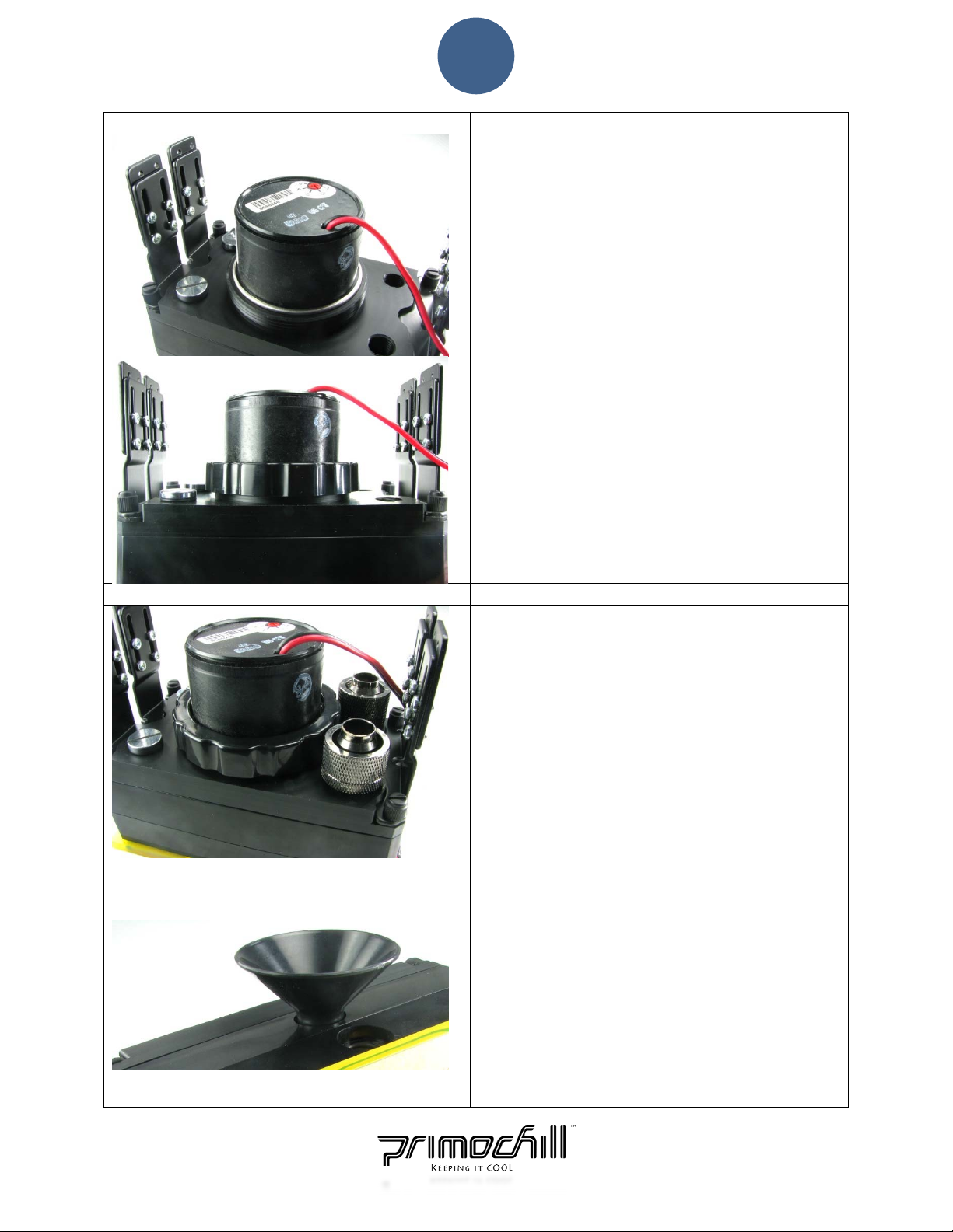
Oncethecentralframeisproperlyfittedtothe
pumphousing,removetherestoftheprotective
paperofftheacrylicfaceplateandlaygentlyonthe
frame.MakesuretheO‐ringisstillinthechannel
andnotprotrudingoutANYWHERE.
Oncethefaceplateisinplace,locatethefourpack
ofM4screwsinthebagWITHOUTtheplasticcaps.
(Seepicturetotheleft).
Gentlyplacethescrewsintotheholes.These
screwsaretobeusedinthecenter4holesONLY.
Gentlytightenthescrewsintheordershowninthe
pictureto80%,thenrepeatto100%.100%should
betheequivalenttohandtighttension.DONOT
OVERTIGHTEN.
ProceedtoStep8.
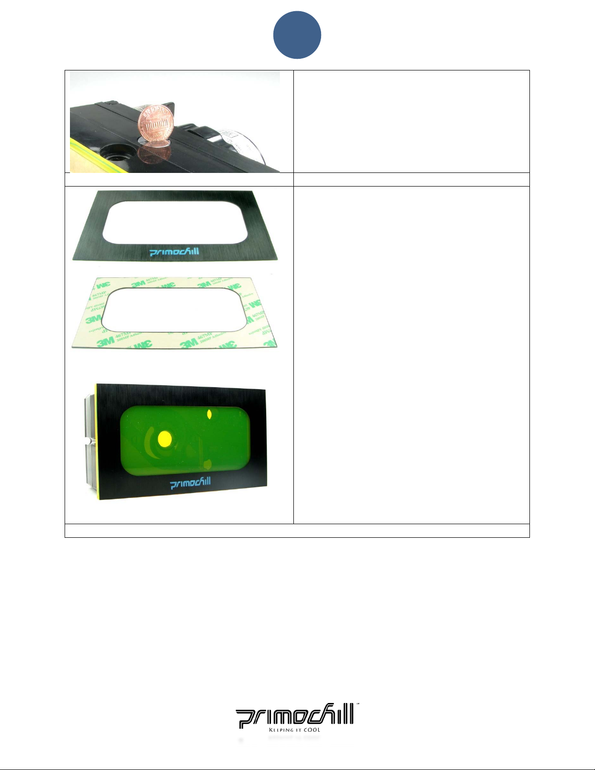
Step8 MountingBracketThroughScrews–4Corners
Withthe4centerscrewsinplace,proceedtopeel
offthepaperonthetwoedgesnexttotheLED
Lightchannel.Leavethecenterpieceunpeeledfor
now.
Onceyoupeeloffthepaperontheedgesyouwill
seetheO‐ringmakingcontactwiththeacrylicface
plateiftheO‐ringhasbeeninstalledproperly.
Locatethe6‐32screwswiththe4plasticcaps.
Insertthescrewsintotheholesandbeginto
tighten.Followthesametighteningprocessasyou
didinStep7.
Tighteningthesescrewstohandtighttensionjust
likethecenterscrewsisadequatetomakeawater
tightseal.IfthesescrewsareovertighteneditWILL
CAUSETHEACRYLICTOCRACK.

6
Thebelowpictureillustratestheleveloftightness
youshouldachieve.IMPORTANT:Ifyouseethat
theacrylicistouching(makingcontact)withthe
framethenthescrewistootight.Untightenthe
screwuntilitdoesnotmakecontactwiththe
frame.ProceedtoStep9.

7
Step9–Box1 DualBayMountingSystem
OptionalThumbscrewsareincludedifyour
specificcomputercaserequiresthem.
Thesebracketsaredesignedtogivethereservoir
moreflexibiltyonwhereandhowthereservoiris
installed.Thefollowingstepsexplainhowto
mountthereservoirintothe2x5¼DriveBays.
a.Assemblethemountingbrackets:
Placethefirstbracketonaflatsurfaceandslide
oneoftheplatesunderneathitandtightenscrews
intoplate.Tightenthescrewsallthewaydown
andthenuntightenapproximately½turnoruntil
theplateslidesbackandforth.Repeatforother
bracket.Thereare8screwsperbrackettobe
installed.ProceedtoStep10.
Step10 MarrybodyWithMount
Now,gentlyplacethereservoironitsface.Next,lay
theanti‐vibrationpadoverthe2exposedscrews
andlineuptheshapetomatchthecut‐outonthe
reservoir.
Finally,lineupthebracketwiththecut‐outshape
andscrewonthenutcaps.Repeatforotherside.
Thesecapssecurethebracketstothereservoirand
allowyoutomountitintoyourdrivebays.
ProceedtoStep11.

8
Step11 InstallD5Pump
Removepumpfromstockhousingandplaceinto
therearpumpmountareaofthereservoir.Next,
slippumpwirethroughthepumpretainingcapand
beginscrewingcapontorearpumpmounthousing,
securingthepumpinplace.Youmayhavetoturn
thecapcounterclockwiseandthenclockwiseto
properlyalignthethreadsevenly.Thecapwillnot
secureproperlyifcrooked.
Finally,tightentheretainingcapuntilitstops
turning.
Aproperlyinstalledcapwillbeperfectlyhorizontal
withthepumpandhousing.Ifthecapiscrookedit
willleak.Unscrewthecapandrepeatuntilthecap
isinstalledproperly.
Step12 FillandTest
Pleasenote:Theoutletwillalwaysbethetop
rightandbottomleftwhenlookingattherearof
thereservoir,nomattertheorientation.
Aswithanywatercoolingproject,testingnew
hardwarebeforeputtingitintoserviceisrequired.
Thefollowingconfigurationisfortestingpurpose
only.
Plugonesideofthereservoir.Ontheothersideof
thereservoirinstall2xG¼BSPPfittingsandasmall
sectionoftubetoloopbackthefluidfromthe
outletbackintothereservoir.Thiswillcreatea
closedloopfortesting.
Nowaddfluidwithsuppliedfunnel.De‐Ionizedor
Distiledwaterisrecommended.Thiswillneedtobe
dumpedoncetestingiscomplete.
Connectpumpto12voltpowersourceandrunfor
aminimumof24hrs.After24hrs,checkforleaks
orpuddlesformingnearthereservoir.Aslongas
yourO‐ringsareinstalledproperlythereshouldbe
noleaks.
Oncetestingiscompletedraintestfluid.
ProceedtoStep13.

9
Step13 FinalInstall
a.InstallBrushAluminumFaceCover:Peelpaper
offthedoublesidedadhesivetapeandsticktothe
acrylicfaceplate.Makesurealltheedgesareflush
andpressstickysideagainstfaceplate.
b.InstallReservoirintoCase:Picktwobaysand
slidein.(InstallationisjustlikeinstallingaDVD
drivethatistwiceastall.)
Insertthereservoirsoitsflushwiththecaseand
tightenthescrewsonthebracketplates.Youmay
needtoremovethereservoirandrepeatthis
processacoupletimestogettheperfectfit.
Onceyouaresatisfiedwiththefit,tightenthe
screwscompletelysothereservoirdoesnotslide.
Youarenowreadytocompletetherestofyour
watercooingrigandreaptherewardsofyournew
reservoir.
Stillhavequestions?ContactusatPrimochill.comorcallustollfreeat(800‐690‐9081).
Other Primochill Water System manuals
Popular Water System manuals by other brands

Graf
Graf one2clean Service instructions

KC
KC 60 Series manual

Clean Water Systems
Clean Water Systems Pro-OX 7800 Installation & start?up guide

Wilo
Wilo Isar BOOST5 Installation and operating instructions

Topper
Topper WOW RO System Installation & user manual

PAW
PAW HeatBloC K34R Installation and operating instructions

Bluevua
Bluevua RO500X6 instruction manual

Hoshizaki
Hoshizaki ROX-20TB2-U instruction manual

Grundfos
Grundfos Auto ADAPT ALPHA2 Installation and operating instructions

WaterLogic
WaterLogic WL800 - MAX II manual

Kenmore
Kenmore 625.385560 UltraFilter 650 owner's manual

Evinox
Evinox ModuSat SP Cooling Unit installation manual