Priolite MBX 500 HotSync User manual

Instruction manual PRI
O
LITE MBX 500 - HotSync
PRI
O
LITE GmbH Wuerzburg - Last revised: 12/2013 - Page 12
Contact information.
PRI
O
LITE GmbH
Gattingerstr. 7
D-97076 Würzburg
Germany
Phone: +49 (0)931 20700000
Internet: http://www.priolite.com
.Declaration of Conformity.
The company PRI
O
LITE GmbH
Gattingerstr. 7, D-97076 Würzburg, Germany
declares that the products
MBX 500 - HotSync
are in conformity with the following standards:
EN 61000-6-3:2007, EN 61000-6-2:2005 and DIN EN 60335
according to the provisions of the Directives
2004/108/EG and 2006/95/EG
Place and date of issue:
Würzburg, 02-December-2013
Dipl.-Ing. Joachim Renschke
Managing Director PRI
O
LITE GmbH

PRI
O
LITE GmbH / Gattingerstr. 7 / D-97076 Würzburg / Tel +49(0)931 20700000 / eMail in[email protected] / http://www.priolite.com
Instruction manual
Instruction manual
MBX 500 - HotSync
MBX 500 - HotSync

Instruction manual PRI
O
LITE MBX 500 - HotSync
PRI
O
LITE GmbH Wuerzburg - Last revised: 12/2013 - Page 2
Introduction.
Dear photographer,
Thank you for selecting the PRI
O
LITE compact flash unit.
As a young, aspiring company, PRI
O
LITE intends to use innovative technologies and high-
quality products to open up new market segments for professional photography.
Our devices are based on state-of-the-art technology and equipped with carefully selected
components. Our production process is continuously monitored to ensure high quality and
safety standards.
Before using this unit, please read the operating manual and safety instructions carefully to
prevent damage to the device and maintain your warranty.
We wish you many successful years of productive and innovative work with our equipment.
Should you have questions about our products, please contact us!
Best regards,
PRI
O
LITE GmbH
Description.
The PRI
O
LITE MBX 500-HotSync is a radio-controllable, battery-operated compact unit
with an exchangeable battery; the power output ranges from 16J to a maximum of 500J
covering 6 f-stops precisely adjustable in 1/10 increments. The flash recycle time to
maximum output is around 2.8 seconds. The modelling lamp for MBX 500 is a LED array.
MBX 500-HotSync is optimized for flash synchronisation up to 1/8000 sec. Therefore, it
provides a long and constant flash duration of 1/200 sec. HotSync function is only usable in
combination with the Priolite Remote Control RC-HS (see the instruction manual).
MBX 500 - HotSync can also be triggered from other sources, but in this case, the flash
sync time is limited to 1/200 sec.
Delivery includes.
1 compact flash PRI
O
LITE MBX 500-HotSync; 1 multi-voltage battery charger 16V; 1 flash-
tube 500J for plug-in; 1 built-in LED array as modelling lamp; 1 protection glass dome; 1
tilting head; 1 synchronization cable; 1 black plastic protective cap for safe transportation.
MBX 500-HotSync series is also available as a kit which includes only one synchronization
cable and one cableset to connect the remote control with the camera. There is also only
one battery charger per kit supplied.
For the composition of the kits, please refer to our currently valid price-list.

Instruction manual PRI
O
LITE MBX 500 - HotSync
PRI
O
LITE GmbH Wuerzburg - Last revised: 12/2013 - Page 11
Maintenance.
Before maintenance are to be done, the following safety precautions must be strictly
observed:
Before replacing the flash tube or the modeling light, the flash unit must be switched
off. Then you must wait at least 5 minutes for safety reasons to ensure the complete
discharge of the capacitors via the internal safety circuit. Furthermore, before
replacing the flash tube, you must wait until it has cooled down.
To remove the glass dome, please refer to the instructions described above. The
flash tube and modelling lamp must not be touched during this procedure (danger!).
Always use extreme caution when handling an exposed flash tube due to the
existing overpressure.
If the glass of the flash tube is broken, do not touch the electrodes in any case when
you are replacing the flash tube! In this case you must use fully insulated pliers to
remove the damaged flash tube!
Replacement of flash tubes
For replacement pull the flash tube carefully out of the plug connector and replace it with a
new one (to be ordered from PRI
O
LITE) by plugging the three contacts into the sockets.
Before using the unit once again the glass dome is to be mounted for safety reasons.
Regular inspection and repairs
Except for the work described in the “Maintenance” section, users may not perform any
repairs on flash systems; these are to be carried out exclusively by authorized customer
service personnel.
In accordance with country-specific safety regulations, inspection and maintenance of
electrical systems and devices should be carried out at regular intervals. We recommend an
annual inspection of the units to ensure operational safety and reliability and to maintain the
value of the system.
Return to customer service
To prevent damage during transport and to ensure optimal protection of the units, we
recommend to ship the devices only in the original packaging.
Disposal
Disused and defective units must be disposed of in the electronic recycling.
.Accessories.
The following accessories are available:
Radio remote control RC-HS, textile & metal lightformers of different shapes and sizes
(reflectors, grids, softboxes, octaforms, striplights, umbrellas), stands, cases & bags, glass
domes, flashtubes, cables, multivoltage chargers, and battery exchange drawers.

Instruction manual PRI
O
LITE MBX 500 - HotSync
PRI
O
LITE GmbH Wuerzburg - Last revised: 12/2013 - Page 10
Flash triggering .
Flashes can be triggered as follows:
Flash triggering via the synchronization cable
The compact flash unit is connected to the camera using a synchronization cable with a 3.5
mm phone jack via the synchronization socket. The synchronization socket is located
besides the photocell in the area of the handle. The synchronization voltage is 5 V.
The synchronization circuit was designed using state-of-the-art semiconductor technology.
This enables reliable flash triggering even in older cameras with mechanical contacts.
However, due to the large number of different electronic circuits used in the cameras for
synchronization control, we cannot assume any liability for any damage to the camera by
triggering the flash. You should therefore contact the camera manufacturer before using
cameras that are not generally commercially available.
Flash triggering via the photocell
The compact flash unit can also be triggered via the built-in photocell. Triggering then
occurs when a flash from another unit “strikes” the first unit. This operating mode is
activated by pressing the Slave button (control LED is on).
The photocell is designed as an impulse photocell. Thus, it works only when the striking
flash has a higher aperture value than the ambient light. You must therefore ensure that no
excessively strong external light falls on the photocell. If this cannot be avoided, another
method of flash triggering must be selected.
Flash triggering via radio remote control
The compact flash unit is equipped with a built-in bi-directional radio module. To trigger the
flash via radio, the radio remote control must be mounted onto the hot shoe of the camera
and then switched on using its main switch. You must also ensure that the TEAM/ID
settings on the radio module and the flash unit match. The flash is triggered by activating
the camera shutter.
Flash triggering via the TEST button
The flash can also be manually triggered by pressing the “TEST” button.
Automatic Power Drop (APD)
If the power setting is reduced, the stored energy is internally dissipated. During this
process no flash will be triggered. Compact flash units that are switched off are
automatically discharged. It is also possible to reduce the energy quickly to the current
value by triggering a test flash.

Instruction manual PRI
O
LITE MBX 500 - HotSync
PRI
O
LITE GmbH Wuerzburg - Last revised: 12/2013 - Page 3
Intended use.
This compact flash unit is intended for mobile use in professional photography in the studio
or on location. Its purpose is the provision of electrical power for flash generation and flash
generation itself. The unit may not be used for any other purpose.
Compact flash units store energy in capacitors by collecting high voltages, which
creates particular sources of danger. Before using this unit, read and comply the
following safety instructions.
Safety instructions.
Flash units may not be operated without supervision.
Always use extreme care when handling the flash unit to prevent damage to the flash
tube. A damaged flash tube poses a risk of severe injury or death, as you can come into
contact with the voltage-carrying electrodes. If this happens, the unit must be switched
off immediately. For safety reasons, before exchanging the flashtube you must wait at
least 5 minutes after switching off the unit to ensure that the capacitors have completely
discharged via the internal safety circuit. The same applies to any type of maintenance
work or before transports, which may be undertaken on the unit only when it has been
switched off and after the waiting period has expired.
Contact with the capacitor voltage is life-threatening; thus, the opening of the casing and
repairs on the compact unit may be carried out only by authorized customer service
personnel.
Only the original PRI
O
LITE charger may be used for charging the batteries. Before
each use, check to ensure that the casing as well as all cables, connectors and sockets
are in good, undamaged condition. Otherwise operation of this device is forbidden;
damaged units and/or cables must only be repaired or replaced by authorized customer
service personnel.
Flash units may be operated only with a properly mounted glass dome, as flash tubes
can explode due to the development of overpressure.
It is particularly important to protect the flash unit from moisture, splash water and
impacts during use or transport. This unit is not designed for operation in dusty
environments. Flash systems may not be used in potentially explosive areas; to prevent
the risk of fire, do not store flammable materials (e.g. decorative materials, paper, etc.)
in the immediate vicinity of the flash units.
Do not insert any objects into the ventilation slots or the charging or synchronization
sockets. The ventilation slots must be kept clear during operation.
Flash units mounted on pantographs or ceiling systems must be doubly secured against
falling down.

Instruction manual PRI
O
LITE MBX 500 - HotSync
PRI
O
LITE GmbH Wuerzburg - Last revised: 12/2013 - Page 4
Do not flash into eyes from a short distance (less than 5 meters) as this can cause injury
to your eyes. Do not look directly into the flash reflector; the flash could be inadvertently
triggered.
Ventilate closed rooms regularly to prevent illegal ozone levels, which can be generated
by the use of high-performance flash units.
Specific safety precautions when working with Lithium-ion batteries.
The provided Lithium-ion battery contains a protection circuit that protects the battery
against overload, deep discharge, short circuit and overheating.
In case of improper use (cutting, breaking, overheating) the batteries can explode or cause
fires, even after a prolonged time interval. Therefore, Lithium-ion batteries are generally to
be protected from mechanical damage and kept away from heat, open flames, and
corrosive liquids. Batteries must not be damaged in any way. Lithium cells generally
respond violently with water (particularly in fully charged condition); therefore, in case of
burning do not extinguish the flames with water, but use sand. Damaged Lithium-ion
batteries are readily to be disposed of in appropriate containers.
Lithium-ion batteries contain flammable and / or corrosive solutions and Lithium salts, which
may cause in the case of leakage irritation to skin, eyes, and mucous membranes. In case
of contact with escaped electrolytes, gases, or fire by-products of a Lithium-ion battery, the
following first aid measures must be observed:
Eyes: In case of contact with eyes, rinse immediately for at least 15 minutes with water.
Keep eyelids open in order to ensure the complete flushing of the eye.
Skin: Take off contaminated clothing and rinse under cold water for at least 15 minutes.
Respiratory system: Ensure fresh air supply. If necessary, perform first aid measures.
In any case, following first aid measures a doctor should be consulted.
Lithium-ion batteries must be only recharged with the supplied PRI
O
LITE charger of the
respective voltage class; use the 16V charger for MBX 500.
The charge should be performed only under supervision and not in close proximity to
combustible materials; sufficient dissipation of heat must be provided (do not charge the
battery in the sun).
If a Lithium-ion battery is carried on air travel, then it must be discharged prior to departure
to avoid any risks.

Instruction manual PRI
O
LITE MBX 500 - HotSync
PRI
O
LITE GmbH Wuerzburg - Last revised: 12/2013 - Page 9
PILOT function box (modelling lamp)
The modelling lamp is switched on or off using the “PILOT” buttons.
MBX 500 is equipped with a LED array as modelling lamp; the light output is equivalent to
that of an 80W halogen lamp. It always lights up with maximum power and is not dimmable.
The mode FREE and PROP is not available.
Bear in mind that longer operation of the modelling lamp consumes battery capacity
which is then no longer available for the flash. Therefore, it is advised to limit the
operation time with the pilot light switched on.
RADIO function box (radio operation)
For remote radio operation, use the three radio buttons on the right.
ON:
If the ON button is activated (control LED lights up), the flash can be triggered and
controlled by radio. Additional entries for TEAM and ID are required.
Team/ID:
Selection of a team (A, B, or C) or an ID (1 to 9) is done by pressing the Team or the ID
button, resp., and simultaneously turning the control knob until the desired selection is
indicated on the LED display. By adjusting all possible combinations, a maximum of 27
flash units (3x9) can be individually triggered and controlled.
Team and ID can be changed only when the radio function is “ON”.
AUXILIARIES function box (additional functions)
Slave:
If the “Slave” button is activated, an external flash is triggered via the photocell (see the
section entitled “Flash triggering” below).
FC:
IF FC (Flash Check) is activated, the modelling lamp goes off immediately after the flash
has been released and lights up again only after the unit has charged up to the selected
level. This ensures correct charging as well as renewed flash readiness. The flash control
ensures that the flash lamps light up when several flash units are used.
Audio:
If the “Audio” button is activated, flash readiness is indicated by an acoustic signal.
Test
Test flashes can be released by pressing the “TEST” button.
For additional flash triggering options, please refer to the next section.
Flash readiness
Flash readiness is indicated by 1.) lighting up of the “TEST” button; 2.) green light of the
plastic cap covering the photocell; 3.) re-lighting up of the modelling lamp when FC is
activated; and 4.) an acoustic signal when the Audio function is switched on.
Instruction manual PRI
O
LITE MBX 500 - HotSync
PRI
O
LITE GmbH Wuerzburg - Last revised: 12/2013 - Page 8
Replacement of battery drawers and connection to the charger
To replace the battery, please proceed as follows: Before exchanging the drawer the device
is to be switched off by using the main switch protected by a flap; the green LED light
located on the left side of the main switch goes off. Then, place your index finger into the
pull-out handle and press your thumb against the bottom flap of the battery drawer. With
combined upward push and pull, the drawer is to be completely removed out of the housing
of the flash unit.
With the battery drawer pulled out of the unit, under no circumstances reach into
the opening of the compact flash device!
An exchange drawer fitted with an original PRI
O
LITE battery of the same voltage class
(MBX 500: 500V) is to be inserted completely into the opening of the flash unit with slight
pressure until it clicks.
The charging of the battery can be done inside the flash unit (switched on or off) or outside
of the housing. The charging cable of the supplied charger (16V) is plugged into the
charging socket of the battery drawer and the provided power cable connected to the mains
outlet. The charging unit is intended for global supply voltages (multivoltage: 230V/115V).
The charging time of a flat battery to full charge is approximately 3 hours. Full charge is
indicated by the lighting up of all 5 LEDs.
The batteries for PRI
O
LITE flash units are of different sizes and weights; in addition,
chargers are also fitted with a different charging plugs. Therefore, please make sure, that
for operation with MBX500-HotSync the correct size of the battery is inserted and the 16V
charger with the 2-pin charging plug is in use.
Functions on the operating panel.
Control knob
The control knob is used to set the desired flash power in 1/10 increments from 500J to a
minimum of 16J covering 6 f-stops for MBX 500. The output is displayed on the two-digit 7-
segment display in f-stops: 10 stands for maximum power and 5.0 for minimum power.
Increasing or decreasing the f-stop by 1.0 point doubles or halves the flash output, rsp.
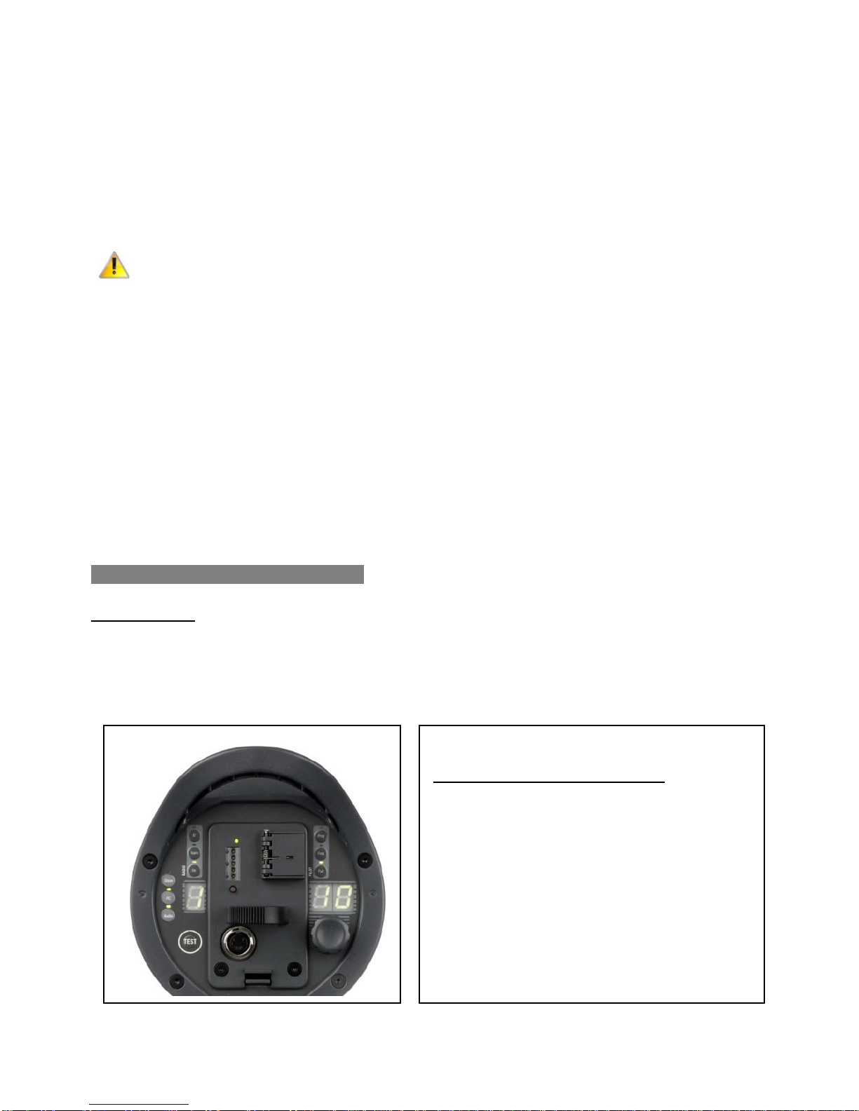
MBX 500-HotSync operating panel
From right to left and top to buttom:
PILOT function box (modelling lamp options)
2-digit LED display
Turning knob
Battery drawer with
> Mains switch behind the flap,
> Pull-out handle and upper/lower flap,
> Charging socket and
> row of LEDs for charging control (top left)
RADIO function box (options for remote control)
1-digit LED-display
Flash release button (TEST)
AUXILIARIES function box (Slave, FC, Audio)

Instruction manual PRI
O
LITE MBX 500 - HotSync
PRI
O
LITE GmbH Wuerzburg - Last revised: 12/2013 - Page 5
Technical data MBX 500 - HotSync .
Output: 500 Ws
Voltage supply: Lithium-ion battery with protection circuit, no
Memory ffect, 16V, 35 Wh, weight approx. 600 g
Modelling lamp: LED array, equivalent to 80W halogen
Flash recycle time: 2.8 sec. at full power
Fastest flash sequence: 2 flashes per second
Flash duration t0.5 (sec): 1/4500 at full power
Color temperature (K): 5500
f-stop (1m distance, 7”reflector, 64,2
ISO100, measuring time 1/125)
shortest sync time: up to 1/8000 sec. depending on the camera
Sync voltage: 5V for safe flash triggering by modern digital cameras.
socket for 3.5 mm phone jack
Flash power control: 1/10 increments, over 6 f-stops
10 = full power (500 Ws), 5 = min. power (16 Ws)
No. of flashes/charge: 220/full power (display ‘10’), 440/250 Ws (display ‘9’)
more than 6000 at low power
Charger: 16V (Multivoltage)
Charging time: approx. 2h to 80% and approx. 3h to full charge
Weight (without tilt): 3,2 kg (battery included)
Dimensions (cm x cm): 40 x 17
Code No.: 01-0500-04
Initial operation.
Set-up and assembly
The compact flash units are equipped as standard with a tilting head. For set-up on
tripods, pantographs or ceiling systems, the tilt is screwed securely onto the
appropriate tripod mount using the locking thumbscrew on the side of the panner.
If the unit is suspended from a pantograph or ceiling rail during operation, a second
secure connection is required in accordance with the applicable safety regulations. It
is recommended to insert a steel cable suitable for this purpose (not included)
through the opening of the handle and to secure it to a suitable lug on the
suspension unit.

Instruction manual PRI
O
LITE MBX 500 - HotSync
PRI
O
LITE GmbH Wuerzburg - Last revised: 12/2013 - Page 6
Adjustment of the tilting head
Dependent on the direction the tilting head is inserted into the rail profile, right and left hand
use is possible. You have the following options for adjusting the flash unit:
The inclination angle can be precisely adjusted by means of the large thumbscrew. The
rotation angle (360 °) is set using the tripod mounting screw.
Using the lateral small thumbscrew on the opposite side, the flash unit can be shifted
backwards or forwards in the rail profile; this might be useful for weight compensation
(e.g., when attaching heavy accessories).
To prevent the unit from sliding off the rail and dropping down, the provided 6-mm
screw is to be inserted into the provided thread hole on the rear end of the rail.
Attachment and removal of the glass dome
The glass dome may be attached or removed only when the compact flash unit is
switched off and disconnected from the power supply. Always ensure that flash tube
and modelling lamp remain intact and undamaged!
The protective glass dome is fixed to the four pre-mounted springs. The best procedure for
mounting and dismounting is to place the flash unit vertically on a solid surface. Then put
the glass dome carefully over the flash tube, and push it down firmly with gentle pressure
until the glass dome snaps audibly into the springs. For dismounting hold the glass dome
firmly with both hands. Then tilt it slightly so that it disengages from the mounting springs
and pull the glass dome straight off.
Mounting of accessories
The compact flash unit must always be set up only at its final usage site and the
corresponding light modifier attachment (reflector, softbox, umbrella, etc.) mounted before
the unit is put into operation. Accordingly, the compact flash unit must always be switched
off before the unit is repositioned or the light modifier is changed.
After longer periods of operation the flash unit and the attached accessories
(particularly reflectors) can become very hot. To avoid burns upon contact, you
should use suitable heat guards when handling the equipment or wait until it has
cooled down. Due to the heat build-up, the compact flash unit must not be operated
in the vicinity of flammable objects. Sufficient safety clearance with regard to
decoration for photographic purposes must be ensured.
Connection of reflectors
To attach reflectors the clamps are put into open position by pressing the reflector lever
against the spring force until it hits the stop and keep it there. Now place the accessory
evenly and flush to the unit (for accessories with Bowens S-type adapter, place the three
flanges of the accessory that they fit into the corresponding recesses). Do not tilt the
accessory during this process. Then return the lever to its initial position moving with the
spring force to lock the accessory into place.

Instruction manual PRI
O
LITE MBX 500 - HotSync
PRI
O
LITE GmbH Wuerzburg - Last revised: 12/2013 - Page 7
To remove the accessory, hold it firmly (caution - it could be very hot!), press the lever
against the spring force to unlock it and remove the accessory.
The system is generally compatible with most reflectors of the Bowens / S-Line as well as
HENSEL / E and EH series. As for HENSEL reflectors, the clamps fit around the raised
edge of the reflector from the outside. Should you have any questions concerning
compatibility, please contact us.
Connection of softboxes
The PRI
O
LITE softboxes have a speedring which is mounted to the flash unit the same
way as reflectors (see description above). For softboxes of other brands adapters are
available upon request. Please ask for details.
Umbrella attachment
To attach an umbrella to the flash unit insert the rod in the round opening at the front of the
rail profile to the desired length and tighten it using the knurled screw.
Acclimatization
If the flash unit is to be set up at a new location with a different humidity level and/or
temperature, the unit should stand for a while before operation in the room in which it is to
be used. This should prevent the formation of leakage current which can develop due to
precipitation.
Overheating
All units are equipped with a fan to prevent damage to the flash tube and the unit itself
during long series of flashes. Nonetheless, should overheating occur, an error message will
appear on the LCD display. The error message will be automatically reset as soon as the
unit has cooled down.
Starting up
Before each operation, the black plastic transportation cap has to be removed.
Compact flash units MBX series are equipped with a removable drawer that contains a
Lithium-ion battery. The battery status is displayed by pressing the button located below the
row of LEDs. If no LED lights up, the battery is discharged. Full charge is indicated by
lightening up of all LEDs. The battery is electronically protected against deep discharge.
If the battery is discharged, either the battery drawer can be easily replaced by a new one
or the battery charger is connected to the flash unit to continue operation. The charger is
designed for multi-voltage operation, i.e., it operates worldwide from 90V - 240V.
The 16V chargers for MBX 500 have a 2-pin connector.
Under no circumstances any manipulation of connectors and / or sockets are to be
made. Only spare parts from PRI
O
LITE are to be used.
Other Priolite Camera Flash manuals


