PRIZM 201840-xxx User manual

VME Dual Port Gigabit Ethernet
Media Converter Board
(P/N 201840 xxx)
User’s Manual
And
Troubleshooting Guide
February 24, 2009
Rev B
Moog Components Group
Springfield Operations
750 West Sproul Road
Springfield, PA 190 4
E-Mail: mcg@moog.com URL: www.moog.com/components
Tel: 610-328-4000 Fax 610-605-6216
24/7 Techn cal Customer Support Hotl ne: 610-605-6101

MOOG CG 201840-xxx VME Dual Port G gab t Ethernet Board Manual, Rev B February 24, 2009
Page 2 of 8
MANUAL REVISION HISTORY
REVISION
NUMBER
DATE BY REASON FOR
REVISION
A 8/7/08 GSG ORIGINAL
B 2/24/09 IB Updated contact nformat on to reflect
Moog Components Group
TABLE OF CONTENTS
1
VME DUAL PORT GIGABIT ETHERNET BOARD, P/N: 201840-XXX ..................................... 3
1.1
VME DUAL PORT GIGABIT ETHERNET BOARD REVISION HISTORY:............................................... 3
1.2
VME DUAL PORT GIGABIT ETHERNET BOARD DASH (-) NUMBER DEFINITIONS ............................ 3
1.3
VME DUAL PORT GIGABIT ETHERNET BOARD OPERATION:........................................................... 4
1.3.1 G gab t Ethernet Board Ind cators and Controls:............................................ 4
1.3.2 VME Dual Port G gab t Ethernet Board Spec f cat ons: ................................ 7
1.3.3 G gab t Ethernet board D mens ons:............................................................... 7
1.3.4 G gab t Ethernet board Power Requ rements: ................................................ 7
1.3.5 Power Sect on Test ng .................................................................................... 7
1.3.6 Opt cal Sect on Test ng................................................................................... 8
1.3.7 Ethernet Test ng .............................................................................................. 8

MOOG CG 201840-xxx VME Dual Port G gab t Ethernet Board Manual, Rev B February 24, 2009
Page 3 of 8
1 VME Dual Port Gigabit Ethernet Board, P/N: 201840 xxx
The Pr zm VME Dual Port G gab t Ethernet Med a Converter board prov des a f ber opt c
l nk to remote two ndependent G gab t Ethernet l nks over f ber opt c cable. Th s board
was des gned to spec f cally to support a G gab t Ethernet sonar – the Reson 7125 but the
board can be used n any appl cat on requ r ng G gab t Ethernet. An ndustry standard
pluggable small-form-factor (SFP) G gab t Ethernet (GBE) f ber opt c module s employed
to allow easy custom zat on of the f ber opt c l nk character st cs. S ngle mode f ber s
typ cally used w th th s board and opt cal l nks can eas ly exceed 10 k lometers. Mult mode
f ber can also be supported but w th drast cally reduced opt cal l nk d stance – typ cally less
than 1 k lometer depend ng on the f ber spec f cs.
Th s board has to be l nked w th another G gab t Ethernet board to complete the Ethernet
connect on.
NOTE: The Gigabit Ethernet board will only work with Gigabit Ethernet devices.
This board will not support 10 or 100 Mbps Ethernet.
The G gab t Ethernet board w ll operate as e ther a subsea or surface nterface board, so t
can be used as a spare for e ther locat on. The opt cal modules used on the board are
nherently b -d rect onal and care must be taken to ensure the correct opt cal port (e ther TX
or RX) s connected, depend ng on the board conf gurat on and system locat on. Wh le the
opt cal module’s rece ver w ll operate on all of the 16 CWDM (coarse wave d v s on
mult plex ng) wavelengths (1270 to 1610nm), the module’s transm tter only em ts at a
s ngle wavelength so care must be taken to ensure the correct wavelength s used.
For non-CWDM appl cat ons, Pr zm can supply the board w th SFP’s that conta n an
nternal b -d rect on WDM (wave d v s on mult plexers) for s ngle-f ber operat on.
1.1 VME Dual Port Gigabit Ethernet Board Revision History:
The G gab t Ethernet board has gone through the follow ng pr nted c rcu t board (PCB) and
Assembly rev s ons:
PCB Rev s on A/Assembly Rev s on A Or g nal des gn..
1.2 VME Dual Port Gigabit Ethernet Board Dash ( ) Number
Definitions
The G gab t Ethernet board has a Dash Number appended to the part number. Th s Dash
Number dent f es the spec f c board conf gurat ons:
-001A or g nal conf gurat on.

MOOG CG 201840-xxx VME Dual Port G gab t Ethernet Board Manual, Rev B February 24, 2009
Page 4 of 8
1.3 VME Dual Port Gigabit Ethernet Board Operation:
The G gab t Ethernet board has three ma n electr cal connectors: two Ethernet RJ-45
connectors and the DIN backplane connector for DC power. The board also has a s ngle 2-
p n Phoen x DC power connector f the board s used w thout a VME rack and backplane.
The RJ-45 connectors (J4 and J7) are located at the left s de of the board and are standard 8-
p n Ethernet connectors w th an ntegrated transformers. The RJ-45 connectors each have a
pa r of ntegrated Ethernet status LEDs.
There s s ngle DIN backplane connector (J1) mounted on the t ght s de of the board for
acqu r ng +5VDC power. Also a green 2-p n Phoen x connector (J2) s located on the on
the lower r ght s de of the board for supply ng the board w th DC operat ng power f the
backplane s not used. P n 1 (upper p n of the J2 connector and labeled “+5V”) s the
+5VDC nput and p n 2 (the bottom p n and labeled “GND”) s the ground.
The SFP opt cal modules (J3 and J6) are located on the left s de of the board.
NOTE: On power up of the board, both LEDs within RJ 45 connectors J4 and J7 will
briefly flash ON then OFF to indicate that the GBE chips (U5 and J9) are starting.
Even if the two boards are optically connected, neither LED on RJ 45 connectors J4
and J7 will light until a valid GBE signal is present at BOTH ends of the fiber optic
link. Once valid GBE signals are seen at both ends of the link then the LEDs on J4
and J7 will activate.
1.3.1 Gigabit Ethernet Board Indicators and Controls:
LEDS:
There are 3 through-hole r ght angle LED nd cators on the top of the board. There are no
LEDs on the bottom of the board.
Top of Board
LED Indication
D3 (Green) Located at the lower r ght of the board, labeled “+5V”, serves as an nd cator that +5VDC
power s ava lable to the board.
D5 (Green) Located on the upper left of the board, labeled “FIBER TRAFFIC #1”. LED bl nks ON
br efly when power s appl ed to the board, otherw se t s not l t.
D7 (Green) Located on the left center of the board, labeled “FIBER TRAFFIC #2”. LED bl nks ON
br efly when power s appl ed to the board, otherw se t s not l t.
D9 (Green) Located on the lower left of the board, labeled ‘TXD #2’, prov des an nd cat on that the
Cypress m croprocessor has responded to a data request from the PMON2 computer. Th s
LED s ON for the durat on of the transm tted data.
D11 (Green) Located on the lower left of the board, labeled ‘RXD #2’, prov des an nd cat on that the
Cypress m croprocessor has rece ved a data request from the PMON2 computer. Th s LED s

MOOG CG 201840-xxx VME Dual Port G gab t Ethernet Board Manual, Rev B February 24, 2009
Page 5 of 8
ON for the durat on of the rece ved data.
D8 (Green) Located on the lower left of the board, labeled ‘TXD #1’, prov des an nd cat on that the
Cypress m croprocessor has responded to a data request from the PMON2 computer. Th s
LED s ON for the durat on of the transm tted data.
D10 (Green) Located on the lower left of the board, labeled ‘RXD #1’, prov des an nd cat on that the
Cypress m croprocessor has rece ved a data request from the PMON2 computer. Th s LED s
ON for the durat on of the rece ved data.
Bottom of Board
LED Indication
D1 (Green) Located at the upper front edge of the board, labeled “+3.3V”, serves as an nd cator that
+3.3V DC s be ng generated by the on-board DC-DC power supply. Supply voltage 5V
must be present for th s LED to be act ve.
D4 (Green) Located on the upper front edge of the board, labeled “FIBER #1”, prov des an nd cat on that
the transce ver module has detected the presence of an nput s gnal on the f ber l nk. When
‘ON’ nd cates that th s board has a good level of rece ved opt cal power from the remote un t
A.
NOTE: THIS LED WILL BE ON WHETHER ETHERNET DATA IS PRESENT OR
NOT.
D6 (Green) Located on the upper front edge of the board, labeled “FIBER #2”, prov des an nd cat on that
the transce ver module has detected the presence of an nput s gnal on the f ber l nk. When
‘ON’ nd cates that th s board has a good level of rece ved opt cal power from the remote un t
B.
NOTE: THIS LED WILL BE ON WHETHER ETHERNET DATA IS PRESENT OR
NOT.
FUSES:
There s one fuse for th s board. All fuses are the self-resett ng PTC type and should
qu re replacement by the user.
F1: 1.1 Amp PTC, DC nput fuse at J2
SWITCHES:
There are no sw tches on th s board.
TRIMPOTS:
There are no tr mpots on th s board.
CONNECTORS:
There are a total of 9 connectors on the board.
J1: 96-p n DIN backplane connector

MOOG CG 201840-xxx VME Dual Port G gab t Ethernet Board Manual, Rev B February 24, 2009
Page 6 of 8
J2: 2-p n Phoen x connector for DC power entry
J2 DC Power 2-p n Phoen x Connector
o
1 +5VDC Input
o
2 Ground
J3: SFP opt cal module for L nk #1
J4: RJ-45 GBE Ethernet connector for L nk #1
J5: 5-p n header for U5 programm ng – do not use
J6: SFP opt cal module for L nk #2
J7: RJ-45 GBE Ethernet connector for L nk #2
J8: 5-p n header for U9 programm ng – do not use
J9: 3-p n Phoen x connector for RS-485 PMON2 D agnost cs
J9 3-p n Phoen x Connector for D agnost cs
o
1 RT+
Left o
o
o
o
o
o
o
o
R ght
J4 G gab t Ethernet
RJ-45 Connector P n # 8
7
6
5
4
3
2
1
P n # 1000Mbps
1 A+
2 A-
3 B+
4 C+
5 C-
6 B+
7 D+
8 D-
Left o
o
o
o
o
o
o
o
R ght
J6 G gab t Ethernet
RJ-45 Connector P n # 8
7
6
5
4
3
2
1
P n # 1000Mbps
1 A+
2 A-
3 B+
4 C+
5 C-
6 B+
7 D+
8 D-

MOOG CG 201840-xxx VME Dual Port G gab t Ethernet Board Manual, Rev B February 24, 2009
Page 7 of 8
o
2 Ground
o
3 RT-
JUMPER POSTS:
There are 4 jumper posts on th s board.
JP1 1 o==o 2 enables SFP Laser transm tter for J3
JP2 1 o==o 2 enables SFP Laser transm tter for J6
JP3 Cypress programm ng header for U12 – do not use
JP4 Cypress programm ng header for U11 – do not use
1.3.2 VME Dual Port Gigabit Ethernet Board Specifications:
Number of Ethernet l nks: 2 per board
Data rates supported: G gab t Ethernet only
1.3.3 Gigabit Ethernet board Dimensions:
Pr nted c rcu t board (PCB): 3.937 nches x 6.299 nches
(100mm x 160 mm)
1.3.4 Gigabit Ethernet board Power Requirements:
The G gab t Ethernet board
ut l zes approx mately 2.5 Watts of power.
• 5.0VDC nput, approx mately 500mA
1.3.5 Power Section Testing
NOTE: The connectors and components on the bottom of the Gigabit Ethernet board
have pins that are connected to internal supply voltages and ground. If these pins are
inadvertently shorted together or to a common chassis ground, the board fuse ( 1) will
trip/reset.
If both the “+5V” LED and the “+3.3V” LED s out:
• Check for cont nu ty of PTC fuse F1 w th an ohmmeter.
• Replace PTC fuse f open.
If only the “+3.3V” LED s out:
• Ver fy +5VDC voltage s present at the source
• Replace the board w th a spare, noth ng repa rable.

MOOG CG 201840-xxx VME Dual Port G gab t Ethernet Board Manual, Rev B February 24, 2009
Page 8 of 8
1.3.6 Optical Section Testing
1.3.7 Ethernet Testing
If the Ethernet l nk s out or has errors:
• As th s board w ll only work w th G gab t Ethernet traff c, ver fy that the dev ces at both
ends of the l nk are ndeed G gab t Ethernet dev ces.
• Ver fy that the Ethernet dev ces at both ends of the l nk are powered up.
• Ver fy that both of the dual LEDS at J4 and J7 are l t to conf rm Ethernet act v ty at the
RJ-45 connector.
• Attempt to PING from one dev ce to the other.
• If the channel s st ll not operat ng correctly, f rst check the f eld w r ng. If the w r ng
appears correct, then f rst replace the subsea G gab t Ethernet board w th a spare and
check the l nk aga n. If the problem s st ll there, replace the surface G gab t Ethernet
board, w th a spare and check the l nk aga n.
This manual suits for next models
1
Popular Network Card manuals by other brands
Sun Microsystems
Sun Microsystems Sun Quad user guide

ATTO Technology
ATTO Technology FastFrame NS12 Installation and operation manual
Sierra Wireless
Sierra Wireless MC5725 Hardware guide
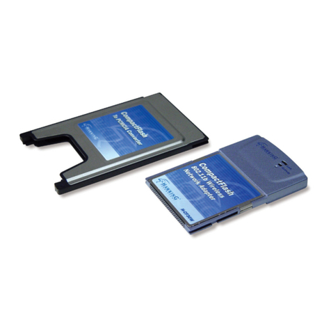
Hawking
Hawking H-CF30W Quick installation guide

Systran
Systran SCRAMNet SC150 user guide
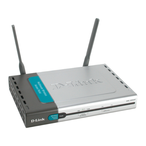
D-Link
D-Link AirPro DWL-6000AP manual
