pro bel 64x64 HD Series User manual

6521 64 X 64 HD SERIES MACHINE CONTROL ROUTER
CONTENTS
1INTRODUCTION 3
2SPECIFICATION 4
2.1 Inputs 4
2.2 Outputs 4
2.3 Control 4
2.4 Power Requirement 4
2.5 Mechanical 4
2.6 Operating Temperature 4
2.7 Connectors 4
3GENERAL DESCRIPTION 5
4ROUTER DESCRIPTION 6
5INSTALLATION 7
5.1 Mechanical 7
5.2 Earthing 7
5.3 Modules 7
5.4 Removal and Replacement Of Sub-Units 8
5.5 Installation Note 8
6CONNECTOR DETAILS 9
6.1 Mains 9
6.2 Switcher Source Connectors (1636 Module) 9
6.3 Switcher Destination Connectors (1636 Module) 9
6.4 Local Control Connector Pinouts on 1537 Termination Panel 10
6.5 PSU Output Monitor (1537) 11
7MAINTENANCE AND WARRANTY 11
7.1 General 11
7.2 Warranty 11
6521
ISS 3 DEC 97 Page 1 6521

MODULE HANDBOOKS INCLUDED
1124 Power Supply Module
1537 PSU/Control Connector Assembly
1636 Input/Output Connector Assembly
2161 16 x 16 HD RS422 Crosspoint Module
2414 HD Series Switcher Control Module
H050 HD Series Local Control Card User Manual
6521
6521 Page 2 ISS 3 DEC 97

1INTRODUCTION
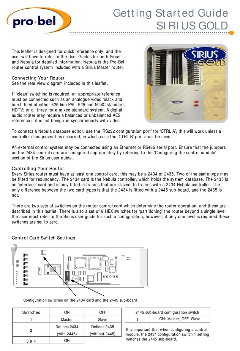
The 6521 is a self-contained mains powered 64 input, 64 output RS422
switcher in a 6U rack frame
6521
ISS 3 DEC 97 Page 3 6521
SOURCES
(A INPUTS, B OUTPUTS)
DESTINATIONS
A OUTPUTS, B INPUTS
NEXT
DESTINATION
GROUP
CROSSPOINT
CARD x 4
49-64
33-48
17-32
1-16
FIG. 1 ROUTER
ARCHITECTURE
1-16

2SPECIFICATION
2.1 Inputs
2.1.1 1636 Module Number and Type: 64 balanced, 4 wire (bi-directional) to EIA
standard RS422A
Impedance: 3k W min
Sensitivity: ±200mV
Input Common
Mode
Rejection: ±12v max
2.2 Outputs
2.2.1 1636 Module Number and Type: 64 balanced, 4 wire (bi-directional) to EIA
standard RS422A
Maximum Ouput
Current: 40mA
2.3 Control Basic Control: 2 ports
4 wire serial RS422/RS485 or RS232 with CTS,
RTS, DTR and DSR
Standard protocol Pro-Bel General
2.4 Power
Requirement Fully equipped
64 x 64: 110/220/240V ac ±10%
50/60Hz at 130 VA; (internal dual power
supplies)
2.5 Mechanical Frame: 6U 19" rack frame
Width: 483mm
Depth: 400mm
Height: 267mm
Weight: 20kg (including dual power supplies)
2.6 Operating
Temperature Range: 0 °C to 40 °C
Cooling: Natural convection
2.7 Connectors Input/Output: 'D' type with screwlock
Control: 'D' type with screwlock
Power: Mains IEC (with latch)
PSU Monitor: 3 pin DIN socket
6521
6521 Page 4 ISS 3 DEC 97

3GENERAL DESCRIPTION
The 6521 consists of a standard 6U, 19" rack frame containing a 6511
motherboard which is powered via dual redundant PSUs and software
controlled (via serial interface type RS422 or RS232). A number of additional
plug in modules are fitted which together form the switcher these are:-
2161 Crosspoint Module
2414 Local Control Module
1124 Power Supply Module
6521
ISS 3 DEC 97 Page 5 6521

4ROUTER DESCRIPTION
The switcher has a minimum of 16 inputs and 16 outputs expandable in
increments of 16 sources and/or 16 destinations.
Switching cards type 2161 house the RS422 crosspoints and local control
latches. The crosspoints are arranged in two blocks of 16 x 16, one block
providing the forward (source to destination) path and the other block forming
the reverse (destination to source) path. The cards also contain RS422
receivers to buffer balanced data into crosspoints and RS422 drivers to output
data from the crosspoints. The crosspoint control, source and destination
address lines are bussed across the 2161 cards to the local control card.
The switching cards contain local on board latches which suits them to a control
system using serial data distribution. This technique reduces non serial control
wiring to individual card handshakes which provide card presence and power
rail status. The remaining control signal bussing comprise serial source and
destination addresses. The local control card is a 6802 microprocessor based
card designed to control routing switchers. It provides for communication with
external microprocessor based control systems/panels. A battery powered
RAM prevents loss of crosspoint selection information in the event of a power
failure.
6521
6521 Page 6 ISS 3 DEC 97

5INSTALLATION
WARNING: For safety reasons the system must not be operated until the
three earthing terminals have been connected correctly.
5.1 Mechanical
The switcher is housed in a 19", 6U high rack mounted frame. All modules plug
into the frame to allow easy access for servicing and are normally protected
behind a hinged front panel. The 6U high cards each have three DIN 41612C
plugs that connect into the motherboard which carries power, signal and control
wiring between cards. Input and output connections are made by ribbon cables
connected to rear plug shells of the motherboard's DIN 41612C connectors.
Extender board type 1336 can be used to gain access to the 6U cards.
5.2 Earthing
Three system earths wired in the frame are accessible on a three-way terminal
block mounted on the rear of the power supplies. The three earths are:
Mains Earth-wired to the earth pin of the mains input connector.
Signal Earth-wired to the system 0V supply and then to the signal cable
screens.
Chassis Earth-wired to the metalwork of the frame and cable connector
metalwork.
These three earths are left entirely separate within the switching system and
can be joined on the terminal block or wired to separate earthing points as
dictated by the nature of the installation.
5.3 ModulesConfirm the correct sub-modules are fitted and pushed fully home with
reference to the label inside the front panel. Check the mains voltage is set
correctly and that the retaining screws and washers are in place. Check the
setting of links on the control card is appropriate for the system.
6521
ISS 3 DEC 97 Page 7 6521

5.4 Removal and Replacement Of Sub-Units
5.4.1 Cards Single card type modules may be removed and replaced with the system
powered or unpowered using card ejectors. When replacing cards, care should
be taken to push them fully home. All cards will work on the 1336 extender
board.
5.4.2 PSUsModule type 1124, a mains powered switch mode power supply, housed within
the frame provides +5V for the switcher cards and control card. It may be
supplied configured for 110 Vac or 220/240 Vac, selected by a link internal to
the PSU.
A 'power on' LED is housed on the power supply front panel in addition to a
socket at the rear which allows external monitoring of both power supply
modules.
Outputs of the 1124 power supply are via diodes, allowing the inclusion of a
second power supply within the frame to provide back up power.
5.4.3 Sub-Assemblies
Sub-assemblies are secured at the rear of the frame by screws and care should
be taken during removal and replacement to support the boards and not to
stress leads. Remove cable connections from the motherboard by holding the
connector shell, not pulling the wires.
5.5 Installation Note
On this unit all 'destination' connectors must be wired to the controller
equipment, and all 'source' to the tributary equipment. The pinouts of these
connectors are such that for direct point-to-point connection between the router
and other equipment a pin to pin cable may be used (e.g. IDC ribbon).
6521
6521 Page 8 ISS 3 DEC 97

6CONNECTOR DETAILS
6.1 Mains IEC 6 Amp
6.2 Switcher Source Connectors (1636 Module)
9 way 'D' screwlock socket.
Wired as Controller, connect to Tributary equipment.
6.3 Switcher Destination Connectors (1636 Module)
9 way 'D' screwlock socket.
Wired as Tributary, connect to Controller equipment
Pin Function
1Chassis
2Rx-
3Tx+
4Tx Common
5N/C
6Rx Common
7Rx+
8Tx-
9Chassis
Pin Function
1Chassis
2Tx-
3Rx+
4Rx Common
5N/C
6Tx Common
7Tx+
8Rx-
9Chassis
6521
ISS 3 DEC 97 Page 9 6521

6.4 Local Control Connector Pinouts On 1537 Termination Panel
6.4.1 RS422/RS485 Serial Control
Cannon 9 way 'D' screwlock socket. Wired as 'Tributary'
6.4.2 RS232 Serial Control
Cannon 25 way 'D' screwlock socket
Pin Function
1Chassis
2Tx-
3Rx+
4Rx Common
5N/C
6Tx Common
7Tx+
8Rx-
9Chassis
Pin Function
1Chassis
2Rx
3Tx
4DTR
5RTS
6DSR
70V
8N/C
9N/C
10 N/C
11 N/C
12 N/C
13 N/C
14 N/C
15 N/C
16 N/C
17 N/C
18 N/C
19 N/C
20 CTS
21 N/C
22 N/C
23 N/C
24 N/C
25 N/C
6521
6521 Page 10 ISS 3 DEC 97

6.5 PSU Output Monitor (1537)
7MAINTENANCE AND WARRANTY
7.1 General No regular maintenance is required on this product or any of
its sub-units. In the case of faults, first check the regulated
power supplies using the PSU monitor points.
7.2 Warranty WARRANTY PERIOD
Hardware Products
Hardware Products are warranted for a period of two years
from the date of shipment. During this period Pro-Bel, at its
discretion, will repair or exchange products proved to be
defective providing that the products are returned to Pro-Bel,
carriage pre-paid. The Company will use its best efforts to
ensure that returned items are repaired and despatched within
ten working days of receipt. Third party items, including PC
hardware or any outsourced equipment is limited to the
original manufacturers warranty, typically one year.
Software Products
Software Products are warranted for a period of ninety days
from the date of shipment. During this period Pro-Bel
undertakes to rectify products proved not to conform to the
published specification provided with the product, when used
in accordance with PC hardware and operating systems
approved by Pro-Bel.
Loans
Within the warranty period, the Company will, at its discretion
and subject to availability, provide loan units pending the
repair of returned items. Loans are offered on a no charge
basis providing that the loan units are returned to Pro-Bel
within a period of twenty one days following the date of
despatch of the repaired items. In the event that the loan units
are not returned within this period, the loan units will be
subject to a monthly overdue charge, details of which are
available on request. Carriage charges apply to all loans.
Pin Function
1PSU 1
2PSU 2
30V
6521
ISS 3 DEC 97 Page 11 6521

NON WARRANTY PERIOD
Outside the stated warranty period, the Company will use it’s
best endeavours to rectify equipment failures through the
provision of spare parts or in house repair services.
Loan units may also be provided subject to availability. All
services and carriage costs are subject to a scale of charges,
details of which are available on request.
WARNING: Ensure that any returned unit is adequately
and appropriately packed; for example, do not pack static
sensitive product in common polythene.
7.2.1 UKCustomers UK customers should return modules for repair marked as
follows:
Customer Support
Pro-Bel Limited
Danehill
Lower Earley
Reading
Berkshire
RG6 4PB
England
Telephone: +44(0)118 986 6123
7.2.2 USCustomers US customers should return modules marked as follows:
Service Department
Pro-Bel America
5 Hub Drive
Melvilly
NY 11747
Telephone: 516 845 2132
7.2.3 Other Customers Other customers should send the unit to their local agent, with
the same information attached.
6521
6521 Page 12 ISS 3 DEC 97
This manual suits for next models
1
Table of contents
Other pro bel Network Router manuals