pro bel Freeway RS422 User manual

P
Pr
ro
o-
-B
Be
el
l
L
Lt
td
d
T
Te
ec
ch
hn
ni
ic
ca
al
l
m
ma
an
nu
ua
al
l
H
HU
U-
-F
Fr
re
ee
ew
wa
ay
y
R
RS
S4
42
22
2
1
1
o
on
nt
te
en
nt
ts
s
1
1
I
In
nt
tr
ro
od
du
uc
ct
ti
io
on
n
3
3
1.1RS422 signal routing 3
1.2Parking 5
1.3Manual and Auto parking 5
1.4The RS422 BroadcastRouter 5
1.5The RS422 Port Router8
2
2
I
In
ns
st
ta
al
ll
la
at
ti
io
on
n
a
an
nd
d
c
co
on
nf
fi
ig
gu
ur
ra
at
ti
io
on
n
9
9
2.1Removal and replacement of module 9
2.2Expanding from 32 ports to 128 ports 10
2.3Setting the level switch 12
2.4Setting the Higher Dest Decode switch14
2.5LED indications 14
2.6The Freeway control card 15
2.7Resetting the module 15
2.8Rearpanel connections for RS42216
2.9Breakout cableconnections 18
3
3
P
Pr
ro
ob
bl
le
em
m
s
so
ol
lv
vi
in
ng
g
1
19
9
4
4
S
Sp
pe
ec
ci
if
fi
ic
ca
at
ti
io
on
n
2
21
1

r
re
ee
ew
wa
ay
y
R
RS
S4
42
22
2
P
Pr
ro
o-
-B
Be
el
l
L
Lt
td
d
2
2
I
Is
ss
su
ue
e
2
2

P
Pr
ro
o-
-B
Be
el
l
L
Lt
td
d
T
Te
ec
ch
hn
ni
ic
ca
al
l
m
ma
an
nu
ua
al
l
H
HU
U-
-F
Fr
re
ee
ew
wa
ay
y
R
RS
S4
42
22
2
3
3
1
1
I
In
nt
tr
ro
od
du
uc
ct
ti
io
on
n
his manual covers the theory of operation and installation of the Freeway RS422
router card. he addition of this module to the Freeway product range gives
considerable flexibility to new and existing router systems, giving the ability to route
control signals with the associated video and audio signals within a single matrix
frame. he Freeway RS422 router improves upon the conventional RS422 router
design by using configurable ports, rather than fixed destination and source
connections; either controller or machine type hardware may be connected to any
port, which will configure itself according to the route made. his concept is further
extended to allow ‘distributive’ routing, so that a single controller can control several
machines, such a configuration is called a Broadcast Router.
he RS422 router card supports 32 ports, and allows expansion, using a further three
cards, to 128 ports, within a single Freeway frame. Details of the RS422 router
configuration and methods of control are held in the Freeway control card database,
which must contain data on any other routers within the Freeway system. Details on
configuring this database via the Windows based editor are contained in the Freeway
Editor Users Guide.
n
n
1
1.
.1
1
R
RS
S4
42
22
2
s
si
ig
gn
na
al
l
r
ro
ou
ut
ti
in
ng
g
RS422 is the name given to a type of digital control signal used extensively in
broadcasting and post production environments. ypical uses of RS422 signals are
for machine control, such as for VRs and Video Servers; and for connecting
hardware such as router control panels, Under Monitor Displays or computer serial
ports. he signal consists of data travelling in two directions (‘bi-directional’), and
each signal is balanced on two wires, to enable transmission over long distances
without interference.
RS422 control signals are bi-directional in order to allow commands from a controller
to be acknowledged by the device under control. Controllers rely on these responses
to confirm that a command has been received, or to report failures or errors.
A signal type known as RS485, or Multidrop, can also be routed, this is particular
type of RS422, which is capable of addressing up to sixteen independent pieces of
hardware ‘daisy chained’ onto one cable; this format is used extensively by Pro-Bel
for connecting control panels and UMDs.

r
re
ee
ew
wa
ay
y
R
RS
S4
42
22
2
P
Pr
ro
o-
-B
Be
el
l
L
Lt
td
d
4
4
I
Is
ss
su
ue
e
2
2
If used for controlling Pro-Bel panels and UMD’s, all daisy chained devices must be
connected to one port and the controller to another.
he terms Controller and Machine are used to determine which wires are used to
receive (RX) and transmit ( X) signals. RS422 connections usually use 9 pin D type
connectors, as follows:
Note: he drawing above refers to the pinout of the connectors with respect to the
controller /machine.
he Freeway RS422 router has two modes of operation, Distributive (Broadcast) and
Non-Distributive (1 to 1), and being a port based router these need to be thought of
from two different perspectives, cabling and control.
As far as cabling is concerned when a device is connected to the router the same
cable connections are used for both modes whether it is a contoller or a machine.
he software within the Freeway router will dynamically configure the ports
depending on how the devices are being used.
From a control point of view the router needs to be considered as sources and
destinations.
When working in Distributive (Broadcast) mode, controllers are treated as sources
and machines are treated as destinations.
he way a device is selected on a control panel (i.e. as a source or as a destination)
will determine how its port is configured. If a device can be a controller or a machine
then it needs to be entered as a source and a destination in the system database and
depending on how it is selected will determine how its port is configured.
TX
TXRX
RX
<< µ
µ
ä
ä
>
>>
>
Controller Machine

P
Pr
ro
o-
-B
Be
el
l
L
Lt
td
d
T
Te
ec
ch
hn
ni
ic
ca
al
l
m
ma
an
nu
ua
al
l
H
HU
U-
-F
Fr
re
ee
ew
wa
ay
y
R
RS
S4
42
22
2
5
5
n
n
1
1.
.2
2
P
Pa
ar
rk
ki
in
ng
g
It is a necessity that the ports on an RS422 router can be ‘parked’, i.e. not routed to
anything. o achieve this, RS422 routers have what is known as a Park Source, which
can be selected by a router control panel in order to disconnect a controller from a
machine. his is not a true source, and is allocated a source number one greater than
the maximum physical number of sources available within the router, which the
controller will interpret as the Park Source.
n
n
1
1.
.3
3
M
Ma
an
nu
ua
al
l
a
an
nd
d
A
Au
ut
to
o
P
Pa
ar
rk
ki
in
ng
g
RS422 router control software also allows for two types of parking, Manual Parking
and Automatic Parking. his is configured in the Freeway database and controls the
way in which routes can be changed. Auto Parking allows routes to be freely changed,
between controllers, machines, or to be parked, effectively allowing any user to move
routes. Manual Parking adds security to the system by only permitting the
connection of controllers or machines that are disconnected, or parked, thereby
requiring that users must disconnect routes before either controller or machine can
be re-routed.
n
n
1
1.
.4
4
T
Th
he
e
R
RS
S4
42
22
2
B
Br
ro
oa
ad
dc
ca
as
st
t
R
Ro
ou
ut
te
er
r
D
Di
is
st
tr
ri
ib
bu
ut
ti
iv
ve
e
o
op
pe
er
ra
at
ti
io
on
n
Audio and Video routers are able to route one Source to many Destinations, this is
known as Distributive, or Broadcast operation. Such routing is not usually
permissible with RS422 signals which are ‘point to point’ in nature, it makes no
operational sense to connect many controllers to one machine, and it is also
electrically compromising. Point to point operation of RS422 routers is usually
governed by the controlling software, and is often known as ‘non-distributive’.
However, it is possible to permit distributive routing of RS422 signals within the
Freeway system by selecting this mode within the database. In this condition,
controllers are treated as if they are sources, and consequently a single controller
may communicate with several machines. In such a situation it must be ensured that
the data flow is not electrically contentious, i.e. data may be sent to all machines, but
must only receive it from one. he Freeway RS422 router allows this mode of
operation in an option called RS422 Broadcast Router.

r
re
ee
ew
wa
ay
y
R
RS
S4
42
22
2
P
Pr
ro
o-
-B
Be
el
l
L
Lt
td
d
6
6
I
Is
ss
su
ue
e
2
2
Operationally, it is the first route made between a machine and a controller that
connects all four wires, and thereby provides the necessary responses. All
subsequent machines connected to the controller will only connect two wires such
that they receive commands but have no response connection:
.
R
Ru
ul
le
es
s
f
fo
or
r
u
us
si
in
ng
g
t
th
he
e
R
RS
S4
42
22
2
B
Br
ro
oa
ad
dc
ca
as
st
t
R
Ro
ou
ut
te
er
r
he user must consider the following rules of operation when making connections
through the broadcast router:
· ports selected as a source will be configured as a controller
· ports selected as a destination will be configured as a machine
· a park source must be defined in the database (see 1.2 Parking)
· to free a controller, all machines connected must be parkedthe crosspoint set
between a parked controller and a parked machine will be bi-
directional
· adding a machine to a routed controller will only connect the machine RX driver
· in manual park mode, only parked controllers and machines can be routed
· in auto park mode, a routed controller may be re-routed, and will park all
machines already connected
· in auto park mode, a machine re-routed from one controller to another will clear
the route with the first controller
· parking a machine with a bi-directional link to a controller will park all machines
using the controller and free the controller
<< µ
µ
ä
ä
>
>>
>
Machines as destinations
Controller as a source Router
RX
RX
RX
RX
TX
TX

P
Pr
ro
o-
-B
Be
el
l
L
Lt
td
d
T
Te
ec
ch
hn
ni
ic
ca
al
l
m
ma
an
nu
ua
al
l
H
HU
U-
-F
Fr
re
ee
ew
wa
ay
y
R
RS
S4
42
22
2
7
7
· a level configured as a broadcast router cannot be associated (married to) other
level types within the system database. Special source/destination associations
need to be set up so that the broadcast level types can be controlled
independently from other level types
· when a bi-directional route isprotected /unprotected, both the controller and the
machine are protected/unprotected
· when a listen only route is protected/unprotected only the machine is
protected/unprotected
· when a bi-directional route is protected/unproteced there is no automatic
protect/unprotect of listen only machines using the same controller
· when a listen only route is protected/unprotected there is no automatic
protect/unprotect of the bi-directional and listen only routes using the same
controller
· when attempting to make/clear a bi-directional route both the controller and
machine must be unprotected. See exception below
· when attempting to make/clear a listen only route the machine must
unprotected. See exception below
· if a bi-directional route is cleared/changed only unprotected listen only machines
will be automatically cleared. See exception below
· xception: Protects are ignored if routes being made were made from a salvo
instigated by a ‘master’ control panel set to ignore protects in salvos

r
re
ee
ew
wa
ay
y
R
RS
S4
42
22
2
P
Pr
ro
o-
-B
Be
el
l
L
Lt
td
d
8
8
I
Is
ss
su
ue
e
2
2
n
n
1
1.
.5
5
T
Th
he
e
R
RS
S4
42
22
2
N
No
on
n
D
Di
is
st
tr
ri
ib
bu
ut
ti
iv
ve
e
P
Po
or
rt
t
R
Ro
ou
ut
te
er
r
When the RS422 router card is selected to Non-Distributive operation in the Freeway
database, only point to point routes are permitted between any single machine and
any one controller. he RS422 router card software will configure any port selected as
a Destination to be a controller and any Source as a machine. Full four wire control
will then be established on any selected route. Any of the RS422 router ports can be
either a machine or a controller, and consequently a port cannot be routed to itself. If
the router is selected to manual parking, a controller or machine cannot be re-routed
until they have been parked.
Machines as sources Controllers as destinationsRouter
<<µ
µ
ä
ä
>
>>
>
<< µ
µ
ä
ä
>
>>
>
<<µ
µ
ä
ä
>
>>
>

P
Pr
ro
o-
-B
Be
el
l
L
Lt
td
d
T
Te
ec
ch
hn
ni
ic
ca
al
l
m
ma
an
nu
ua
al
l
H
HU
U-
-F
Fr
re
ee
ew
wa
ay
y
R
RS
S4
42
22
2
9
9
2
2
I
In
ns
st
ta
al
ll
la
at
ti
io
on
n
a
an
nd
d
c
co
on
nf
fi
ig
gu
ur
ra
at
ti
io
on
n
n
n
2
2.
.1
1
R
Re
em
mo
ov
va
al
l
a
an
nd
d
r
re
ep
pl
la
ac
ce
em
me
en
nt
t
o
of
f
m
mo
od
du
ul
le
e
he module can be removed from the frame or replaced, powered or un-powered,
using the following procedure. When removing the bottom card it is necessary to
remove the door before continuing. For removal purposes it is advisable to remove
the ribbon cables first and then the cards.
· release the ribbon cables by pushing the catches up on either end of the
connector as shown
· lift up the card ejector on the module and gently pull the card out
Replacement is the reverse of above:
· slide the card along the guide rail of the required slot, gently pushing it fully
home until it marries up with the connector on the motherboard
Catches
Topview
Front view
r
re
ee
ew
wa
ay
y
R
RS
S4
42
22
2
P
Pr
ro
o-
-B
Be
el
l
L
Lt
td
d
1
10
0
I
Is
ss
su
ue
e
2
2
n
n
2
2.
.2
2
E
Ex
xp
pa
an
nd
di
in
ng
g
f
fr
ro
om
m
3
32
2
p
po
or
rt
ts
s
t
to
o
1
12
28
8
p
po
or
rt
ts
s
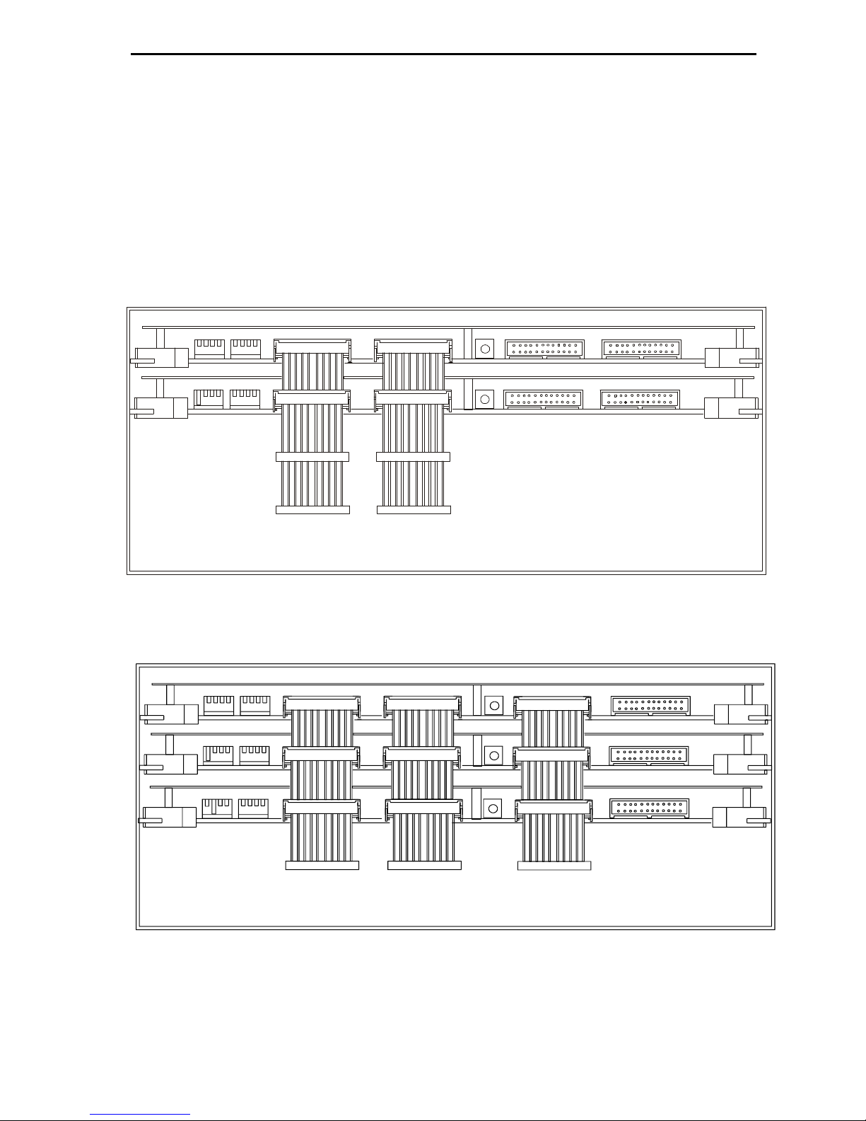
he following diagrams show the cable connections required for expanding the
router from a single card 32 port router up to a four card 128 port router:
6
6
4
4
p
p
o
o
r
r
t
t
e
e
x
x
p
p
a
a
n
n
s
s
i
i
o
o
n
n
9
96
6
p
po
or
rt
t
e
ex
xp
pa
an
ns
si
io
on
n

P
Pr
ro
o-
-B
Be
el
l
L
Lt
td
d
T
Te
ec
ch
hn
ni
ic
ca
al
l
m
ma
an
nu
ua
al
l
H
HU
U-
-F
Fr
re
ee
ew
wa
ay
y
R
RS
S4
42
22
2
1
11
1
1
1
2
2
8
8
p
p
o
o
r
r
t
t
e
e
x
x
p
p
a
a
n
n
s
s
i
i
o
o
n
n

r
re
ee
ew
wa
ay
y
R
RS
S4
42
22
2
P
Pr
ro
o-
-B
Be
el
l
L
Lt
td
d
1
12
2
I
Is
ss
su
ue
e
2
2
n
n
2
2.
.3
3
S
Se
et
tt
ti
in
ng
g
t
th
he
e
l
le
ev
ve
el
l
s
sw
wi
it
tc
ch
h
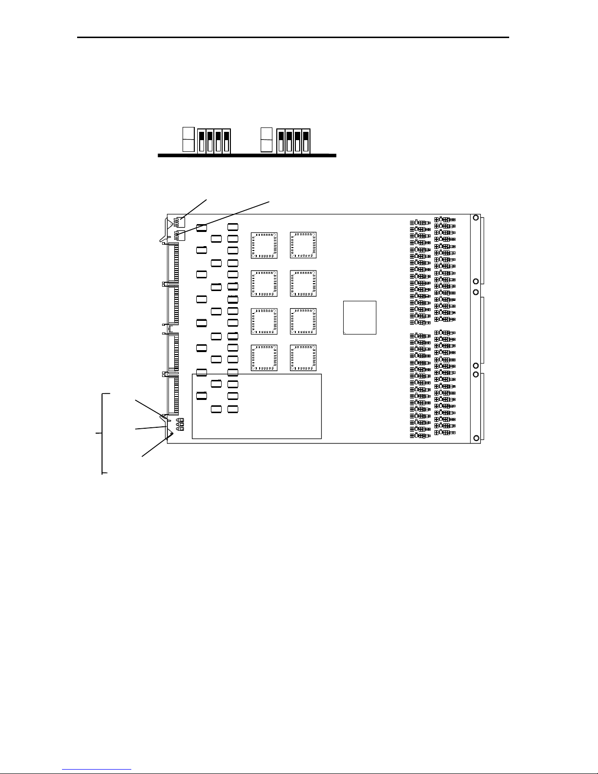
he card edge controls and indicators on the router card are limited to the Level and
Higher Destination Decode switches and a 3 LED array, both of which are described in
part one of the Freeway Series User guide.
For separate routers to be controlled independently, each must have a different level
address set. his operation is achieved by means of the DIL switch marked level on
the front of each Freeway card.
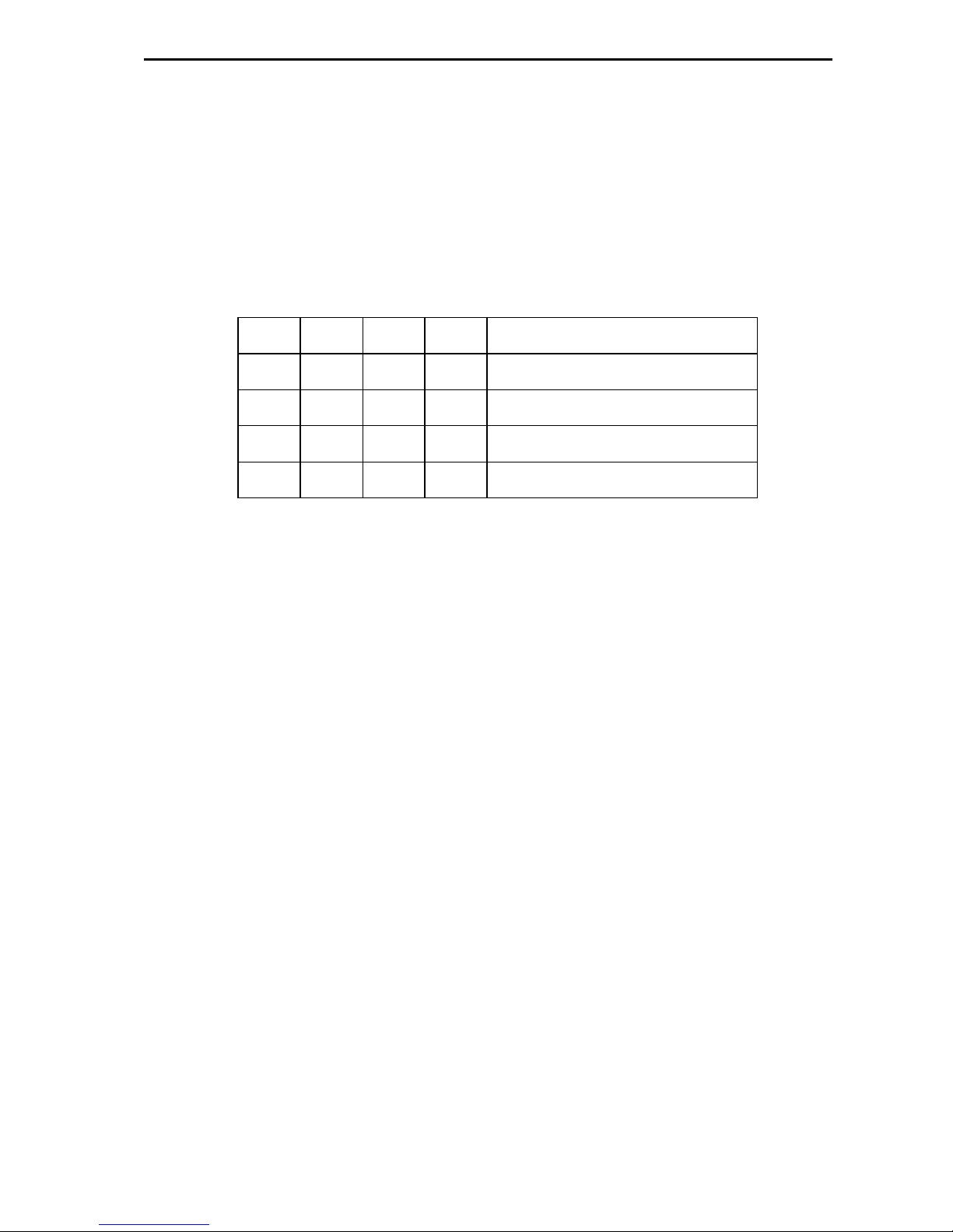
he levels are set thus:
SW 1 SW 2 SW 3 SW 4 Level No
0 0 0 0 1
1 0 0 0 2
0 1 0 0 3
1 1 0 0 4
0 0 1 0 5
1 0 1 0 6
0 1 1 0 7
1 1 1 0 8
he maximum total number of independent levels is 8. A typical system might be
arranged like this:
Level 1 Serial Digital Video
Level 2 Analogue Video
Level 3 AES Digital Audio
Level 4 Stereo Analogue Audio
Level 5 RS422 control
P
Pr
ro
o-
-B
Be
el
l
L
Lt
td
d
T
Te
ec
ch
hn
ni
ic
ca
al
l
m
ma
an
nu
ua
al
l
H
HU
U-
-F
Fr
re
ee
ew
wa
ay
y
R
RS
S4
42
22
2
1
13
3
Higher Dest Decode
SW1
SW2
Level
Off
On
On
Off
1
0
1
0
Viewfrom front ofcard:
switch upfor Off
switch downfor On
Hello
+5V
-5V
Green
LEDs
Control card
r
re
ee
ew
wa
ay
y
R
RS
S4
42
22
2
P
Pr
ro
o-
-B
Be
el
l
L
Lt
td
d
1
14
4
I
Is
ss
su
ue
e
2
2
n
n
2
2.
.4
4
S
Se
et
tt
ti
in
ng
g
t
th
he
e
H
Hi
ig
gh
he
er
r
D
De
es
st
t
D
De
ec
co
od
de
e
s
sw
wi
it
tc
ch
h
he switch marked ‘HIGHER DES DECODE’ tells each card what range of ports it’s
assigned to. his switch must be set correctly for each card according to the
configuration of the system and how the rear connectors are used. he range is
assigned as follows:
SW 1 SW 2 SW 3 SW 4 Port Range
0 0 x x 1-32
1 0 x x 33-64
0 1 x x 65-96
1 1 x x 97-128
n
n
2
2.
.5
5
L
LE
ED
D
i
in
nd
di
ic
ca
at
ti
io
on
ns
s
wo of the three LEDs indicate that power is arriving at the board. Freeway routers
operate from two rails only (where others are needed these are generated on the
Freeway cards themselves). he two rails are +5V and -5V.
he third LED is labelled ‘HELLO’. his is useful in determining if the control system
has spoken to a particular board and, specifically, to tell you if you set the ‘level’ and
‘higher dest decode’ switches correctly.
When the control system sends a command (say in response to a button push), the
appropriate part of the router responds, depending on how the board configuration
switches are set.
If a board receives a command on which it should act, it ‘winks’ the ‘HELLO’ LED.
Meaning, Hello, I’ve just received a command that’s relevant according to my
programmed place in the scheme of things.’

P
Pr
ro
o-
-B
Be
el
l
L
Lt
td
d
T
Te
ec
ch
hn
ni
ic
ca
al
l
m
ma
an
nu
ua
al
l
H
HU
U-
-F
Fr
re
ee
ew
wa
ay
y
R
RS
S4
42
22
2
1
15
5
n
n
2
2.
.6
6
T
Th
he
e
F
Fr
re
ee
ew
wa
ay
y
c
co
on
nt
tr
ro
ol
l
c
ca
ar
rd
d
Central to the operation of the Freeway router is the control card. he card is a sub-
module fitted to any one of the router cards in the system and is used to control and
configure the router. Optionally, two cards may be fitted to provide backup in the
event that one microprocessor card should fail. Full details on configuring the control
card are given in Section 6 of the Freeway echnical Manual.
he Freeway RS422 card may or may not therefore host a control card. If it does, then
a card reset may be performed as described in the following section.
n
n
2
2.
.7
7
R
Re
es
se
et
tt
ti
in
ng
g
t
th
he
e
m
mo
od
du
ul
le
e
here are physically two RESE switches available to perform a hard reset of the
Freeway controller. One is located on the edge of the 2440 sub-module and the other
is remotely located on the front edge of the host card on which the 2440 is sited.
Pressing either has the same effect.
Initiating a hard reset is akin to powering down and powering up the frame housing
the control card. he controller re-boots and follows the usual power-up sequence. It
should be noted that the panels will shut down and then be restored after
initialisation has completed. It should also be noted that resetting the active
controller in a dual control environment will cause system changeover.
If no changes have been made to the database, then no crosspoints will be changed.
Crosspoint settings may change if the level type for a level was changed prior to the
reset, as during initialisation the crosspoints are set according to the level type for
that level.
It is also advisable to perform a reset after database parameters are changed as
certain changes only take effect after a reset, i.e. changing level type, panel type,
source overrides, and controllable destinations.

r
re
ee
ew
wa
ay
y
R
RS
S4
42
22
2
P
Pr
ro
o-
-B
Be
el
l
L
Lt
td
d
1
16
6
I
Is
ss
su
ue
e
2
2
n
n
2
2.
.8
8
R
Re
ea
ar
r
p
pa
an
ne
el
l
c
co
on
nn
ne
ec
ct
ti
io
on
ns
s
f
fo
or
r
R
RS
S4
42
22
2
he rear panel has four 50 way ‘D’ type fixed sockets, providing connections for 32
ports, each with an A and B circuit pair. A and B configure themselves to be receive
(RX) or transmit ( X) circuits according to user selection (see Section 2.2). he pinout
details for ports 1 to 32 are as follows:
Ports 9-16
Ports 1-8
Pin Function Pin Function Pin Function Pin Function
1 Chassis 50 Chassis 1 Chassis 50 Chassis
34 A9 Gnd 42 A13 Gnd 34 A1 Gnd 42 A5 Gnd
18 A9 + 26 A13 + 18 A1 + 26 A5 +
2 A9- 10 A13- 2 A1- 10 A5-
3 B9 Gnd 11 B13 Gnd 3 B1 Gnd 11 B5 Gnd
35 B9+ 43 B13+ 35 B1+ 43 B5+
19 B9- 27 B13- 19 B1- 27 B5-
36 A10 Gnd 44 A14 Gnd 36 A2 Gnd 44 A6 Gnd
20 A10+ 28 A14+ 20 A2+ 28 A6+
4 A10- 12 A14- 4 A2- 12 A6-
5 B10 Gnd 13 B14 Gnd 5 B2 Gnd 13 B6 Gnd
37 B10+ 45 B14+ 37 B2+ 45 B6+
21 B10- 29 B14- 21 B2- 29 B6-
38 A11 Gnd 46 A15 Gnd 38 A3 Gnd 46 A7 Gnd
22 A11+ 30 A15+ 22 A3+ 30 A7+
6 A11- 14 A15- 6 A3- 14 A7-
7 B11 Gnd 15 B15 Gnd 7 B3 Gnd 15 B7 Gnd
39 B11+ 47 B15+ 39 B3+ 47 B7+
23 B11- 31 B15- 23 B3- 31 B7-
40 A12 Gnd 48 A16 Gnd 40 A4 Gnd 48 A8 Gnd
24 A12+ 32 A16+ 24 A4+ 32 A8+
8 A12- 16 A16- 8 A4- 16 A8-
9 B12 Gnd 17 B16 Gnd 9 B4 Gnd 17 B8 Gnd
41 B12+ 49 B16+ 41 B4+ 49 B8+
25 B12- 33 B16- 25 B4- 33 B8-
50
1

P
Pr
ro
o-
-B
Be
el
l
L
Lt
td
d
T
Te
ec
ch
hn
ni
ic
ca
al
l
m
ma
an
nu
ua
al
l
H
HU
U-
-F
Fr
re
ee
ew
wa
ay
y
R
RS
S4
42
22
2
1
17
7
Ports 25-32
Ports 17-24
Pin Function Pin Function Pin Function Pin Function
1 Chassis 50 Chassis 1 Chassis 50 Chassis
34 A25 Gnd 42 A29 Gnd 34 A17 Gnd 42 A21 Gnd
18 A25 + 26 A29 + 18 A17 + 26 A21 +
2 A25- 10 A29- 2 A17- 10 A21-
3 B25 Gnd 11 B29 Gnd 3 B17 Gnd 11 B21 Gnd
35 B25+ 43 B29+ 35 B17+ 43 B21+
19 B25- 27 B29- 19 B17- 27 B21-
36 A26 Gnd 44 A30 Gnd 36 A18 Gnd 44 A22 Gnd
20 A26+ 28 A30+ 20 A18+ 28 A22+
4 A26- 12 A30- 4 A18- 12 A22-
5 B26 Gnd 13 B30 Gnd 5 B18 Gnd 13 B22 Gnd
37 B26+ 45 B30+ 37 B18+ 45 B22+
21 B26- 29 B30- 21 B18- 29 B22-
38 A27 Gnd 46 A31 Gnd 38 A19 Gnd 46 A23 Gnd
22 A27+ 30 A31+ 22 A19+ 30 A23+
6 A27- 14 A31- 6 A19- 14 A23-
7 B27 Gnd 15 B31 Gnd 7 B19 Gnd 15 B23 Gnd
39 B27+ 47 B31+ 39 B19+ 47 B23+
23 B27- 31 B31- 23 B19- 31 B23-
40 A28 Gnd 48 A32 Gnd 40 A20 Gnd 48 A24 Gnd
24 A28+ 32 A32+ 24 A20+ 32 A24+
8 A28- 16 A32- 8 A20- 16 A24-
9 B28 Gnd 17 B32 Gnd 9 B20 Gnd 17 B24 Gnd
41 B28+ 49 B32+ 41 B20+ 49 B24+
25 B28- 33 B32- 25 B20- 33 B24-
For each additional RS422 card fitted in a system, there will be an additional
connector panel located in the corresponding position on the rear of the frame. he
pinout sequence is exactly the same on each connector, with the appropriate offset
applied:
Card two: ports 33 to 64 Card three: ports 65 to 96
Card four: ports 97 to 128
50
1

r
re
ee
ew
wa
ay
y
R
RS
S4
42
22
2
P
Pr
ro
o-
-B
Be
el
l
L
Lt
td
d
1
18
8
I
Is
ss
su
ue
e
2
2
n
n
2
2.
.9
9
B
Br
re
ea
ak
ko
ou
ut
t
c
ca
ab
bl
le
e
c
co
on
nn
ne
ec
ct
ti
io
on
ns
s
RS422 connections are usually wired using 9 pin ‘D’ type connectors. A breakout
cable using one 50 way male D type connector and eight 9 way female D type
connectors is available, part number 1748, to provide direct interfacing between the
Freeway rear panel and other equipment. It is wired as follows:
50 way D type 9 way D type
Circuit pin number
A Ground 6
A Signal + 7
A Signal - 2
B Ground 4
B Signal + 3
B Signal - 8
Refer to Section 2.7 for 50 way D type pinout details.

P
Pr
ro
o-
-B
Be
el
l
L
Lt
td
d
T
Te
ec
ch
hn
ni
ic
ca
al
l
m
ma
an
nu
ua
al
l
H
HU
U-
-F
Fr
re
ee
ew
wa
ay
y
R
RS
S4
42
22
2
1
19
9
3
3
P
Pr
ro
ob
bl
le
em
m
s
so
ol
lv
vi
in
ng
g
T
Th
he
e
g
gr
re
ee
en
n
L
LE
ED
Ds
s
o
on
n
t
th
he
e
r
ro
ou
ut
ti
in
ng
g
c
ca
ar
rd
d
a
ar
re
e
o
of
ff
f?
?
here is no power on the card.
· check that there is power from the PSUs
· check cable interconnections
· ensure that the card is properly seated in the frame
T
Th
he
e
H
HE
EL
LL
LO
O
L
LE
ED
D
o
on
n
t
th
he
e
c
ca
ar
rd
d
r
re
em
ma
ai
in
ns
s
o
of
ff
f?
?
No command has been received by the board.
· check the power
· check that the ‘level’ and ‘higher dest decode’ switches are set correctly
· check cable interconnections
· check that level is configured in database
T
Th
he
e
r
ro
ou
ut
te
er
r
w
wi
il
ll
l
n
no
ot
t
p
pa
as
ss
s
d
da
at
ta
a?
?
Commands are received but not implemented.
· check all LEDs as above
· check the wiring of the ports
· use an RS422 checker to confirm presence of data on ports
· park ports before routing (manual parking mode)

r
re
ee
ew
wa
ay
y
R
RS
S4
42
22
2
P
Pr
ro
o-
-B
Be
el
l
L
Lt
td
d
2
20
0
I
Is
ss
su
ue
e
2
2
Table of contents
Other pro bel Network Router manuals


