Pro Boat SUNRISE 24 User manual

Specifications
Length .......................................................................................................... 24 in (609.6 mm)
Beam .............................................................................................................. 6 in (152.4 mm)
Main Sail Area.............................................................................................. 199 in2 (1284 cm2)
Jib Sail Area.................................................................................................. 87 in2 (561.3 cm2)
Mast Height .................................................................................................. 36 in (914.4 mm)
Overall Height .............................................................................................. 47 in (1193.8 mm)
Radio System.......................................................................... JR AM Beat Gear (RTR Version)
Instruction Manual
™

2
Thank you for purchasing the ProBoat™Sunrise™24 Ready-To-Run
sailboat. This sailboat has been designed to provide many hours
of scale sailing pleasure, without the long hours of assembling
that is usually associated with a model R/C sailboat. The Sunrise 24
can be completed in less than an hour of assembly time.
No Building!
The Sunrise 24 comes almost completely assembled. Its durable
molded fiberglass hull has been painted for your convenience.
You will only need to finish rigging the sails and attach the rudder.
The detailed instructions, photos, and glossary at the back of
the manual will allow you to easily complete the assembly. A
box is provided for each step of the manual so that you can check
off that particular section when complete.
Radio
RTR Sunrise (PRB2170)
Your RTR Sunrise comes with the JR Beat Gear 2-channel AM
radio system installed. Please refer to the manual of the Beat
Gear radio system before attempting to sail your Sunrise. This
manual will answer any questions that you may have regarding
the radio system.
ARR Sunrise (PRB2171)
Your ARR Sunrise arrives ready for radio installation and completely
assembled. A 2-channel radio system is needed to complete it.
Please follow your radio system instructions for the set up. The sail
servo arm is included with the Sunrise, and the rigging line has
already been attached to the sail servo arm to make installation
easier. Please refer to the box art to see a photo that shows how
the radio box should appear when installation is complete.
Introduction .............................................................................................................................................................................................. 2
Section 1—Inspection of Sunrise 24 ........................................................................................................................................................ 2
Section 2—Completing the Boat............................................................................................................................................................ 3-8
Section 3—Installation of Batteries for Radio Transmitter and Receiver .................................................................................................. 9
Section 4—Checking the Radio System.................................................................................................................................................... 9
Section 5—Sailing Tips ...................................................................................................................................................................... 9-10
Basic Glossary..........................................................................................................................................................................................11
Replacement Parts .................................................................................................................................................................................. 12
Plastic Parts ............................................................................................................................................................................................13
Carefully remove the boat, boat stand, and radio transmitter
from the box. Inspect the boat and make certain that no
damage is present. If you notice any damage, please contact
the ProBoat retailer where it was purchased.
Introduction
Table of Contents
Section 1—Inspection of Sunrise 24

3
Section 2—Completing the Boat
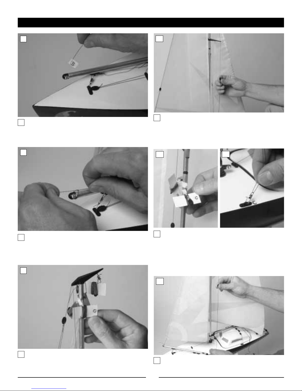
Locate the cardboard box that contains the sails and hardware.
Remove the two-piece mast (one part of the mast will have
the sails rolled around them). Also remove the rudder, boat
stand, and small hardware bag.
Carefully place the hull on the boat stand. Note the two-piece
mast, rudder, and hardware bag.
Insert the joined mast into the hull as shown above.
Carefully unroll the sails from the mast. The main sail will be
attached to the top of the mast at the crane, and the jib sail will
be attached at the triangular shaped spreader.
Locate the main sail boom. It will have an "A" on one end.
After removing the brass eyelet and the included screw from
the gooseneck labled "H", install the boom and secure it
as shown.
Join the mast halves as shown.
View of previous completed step
Crane
1
2
3
4
5
6
4
Locate the jib sail boom. It will have a "B" sticker on one end.
Find the rig line from the jib sail that is marked "B". Remove
the tape from the line and insert it through the eyelet.
After pulling the rig line through the eyelet, make certain that
the space between the bottom of the sail and the sail boom is
approximately 1/2" to 1" (see photo 23). Now, tie a secure
knot in the line.
Locate the jib stay on the rigging line. Pull up carefully on the
jib stay to adjust the tension as shown until there is no slack
in the line, but the mast is still completely vertical.
Carefully unwrap the top rigging line that is marked "C."
Insert the line into the spreader as shown.
Note: The spreader has a small factory made slot in the outer
hole. The inner hole will not be used. This makes it much
easier to insert the line into. You can simply push the rigging
line through the slot.
After feeding the rigging line through the spreader, open the
rigging clip and attach it into the eye plate marked "C." Close
the wire clip. Repeat this step with the lower rigging line
that is marked "C." This lower rigging line is located directly
below the black spreader, and it will also clip to the eye plate
that is labeled "C." When you have completed this step, both
rigging lines marked "C" will be clipped to the eyelet marked "C."
Section 2—Completing the Boat (continued)
Lower
Rigging
Line
7
8
9
10
11 12
13

5
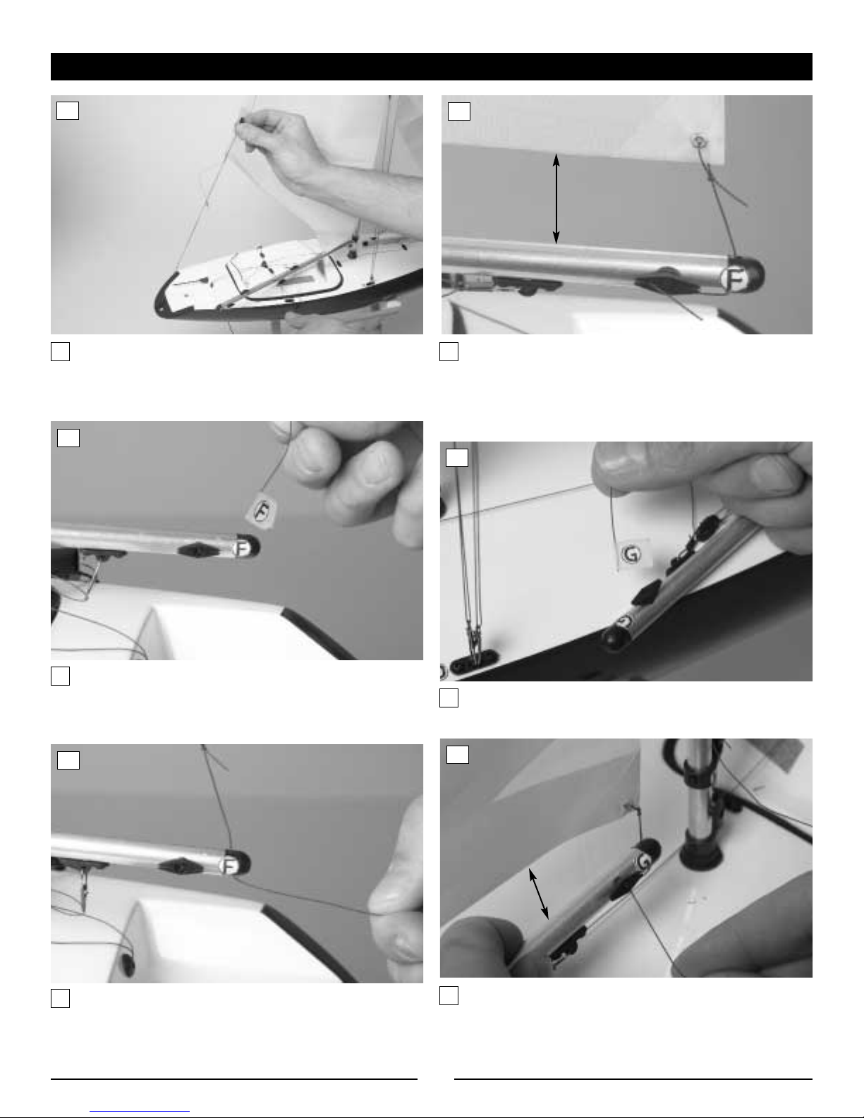
Locate the top rigging line that is marked "D." Carefully unwrap
the line. After feeding the rigging line into the spreader
proceed to the eyelet labeled “D” and clip into the eyelet
(refer to photo 16).
Locate the lower rigging line just below the spreader marked "D."
Carefully unwrap the rigging line.
Clip the rigging line into the eyelet marked "D" as shown. At
the end of this step, both rigging lines that were marked "D"
will be clipped to the above eyelet marked "D."
Locate the jib stay on the rigging line and pull up carefully on
the jib stay to adjust the tension slightly taught as shown.
Again, there should be no slack but the mast should remain
completely vertical.
Locate the rigging line at the top of the mast marked "E."
Carefully unwrap the line.
Proceed directly to the eye plate on the rear of the hull
marked "E." Clip the rigging line as shown.
Section 2—Completing the Boat (continued)
14
15
16
17
18
19
Spreader
6
Locate the jib stay on the rigging line and pull up carefully on
the jib stay to adjust the tension as shown. Remove all
unnecessary slack as was done in prior steps.
Locate the main sail boom. You will find that one side of it is
labeled "F." Locate the rigging line from the back of the main
sail that also is labeled "F."
Remove the label from the rigging line. Next, insert the
rigging line into the eyelet of the sail boom as shown.
After the rigging line has been inserted through the eyelet,
adjust the space between the bottom of the sail and the boom
until it is 1/2" to 1". Wrap the line around the black cleat that is
attached to the boom as shown. Secure the excess line inside
the grooves of the cleat.
Locate the jib sail boom. The back side of it is labeled "G."
Locate the rigging line from the back of the sail as shown.
Remove the label from the rigging line and insert the line
through the eyelet as shown. Once again, make certain the the
space between the bottom of the sail and the boom is approxi-
mately 1/2" to 1". Wrap the excess line around the black cleat as
shown. Secure the excess line inside the grooves of the cleat.
Section 2—Completing the Boat (continued)
1⁄2"–1"
20
21
22
23
24
25
1⁄2"–1"

7
Locate the front of the main sail and find the rigging line
marked "H." Remove the label from the rigging line and insert
it into the inner eyelet of the gooseneck ("H"). The main sail
boom should be already attached to the outer hole of this
gooseneck. Leave approximately 1/2" to 1" of space between
the bottom of the sail and the boom and secure around the
black cleat below the letter "H."
Locate the rigging line from the main sail boom that is
labeled "I."
Clip the rigging line to the lower gooseneck as shown.
Adjust the tension with the jib stay as shown.
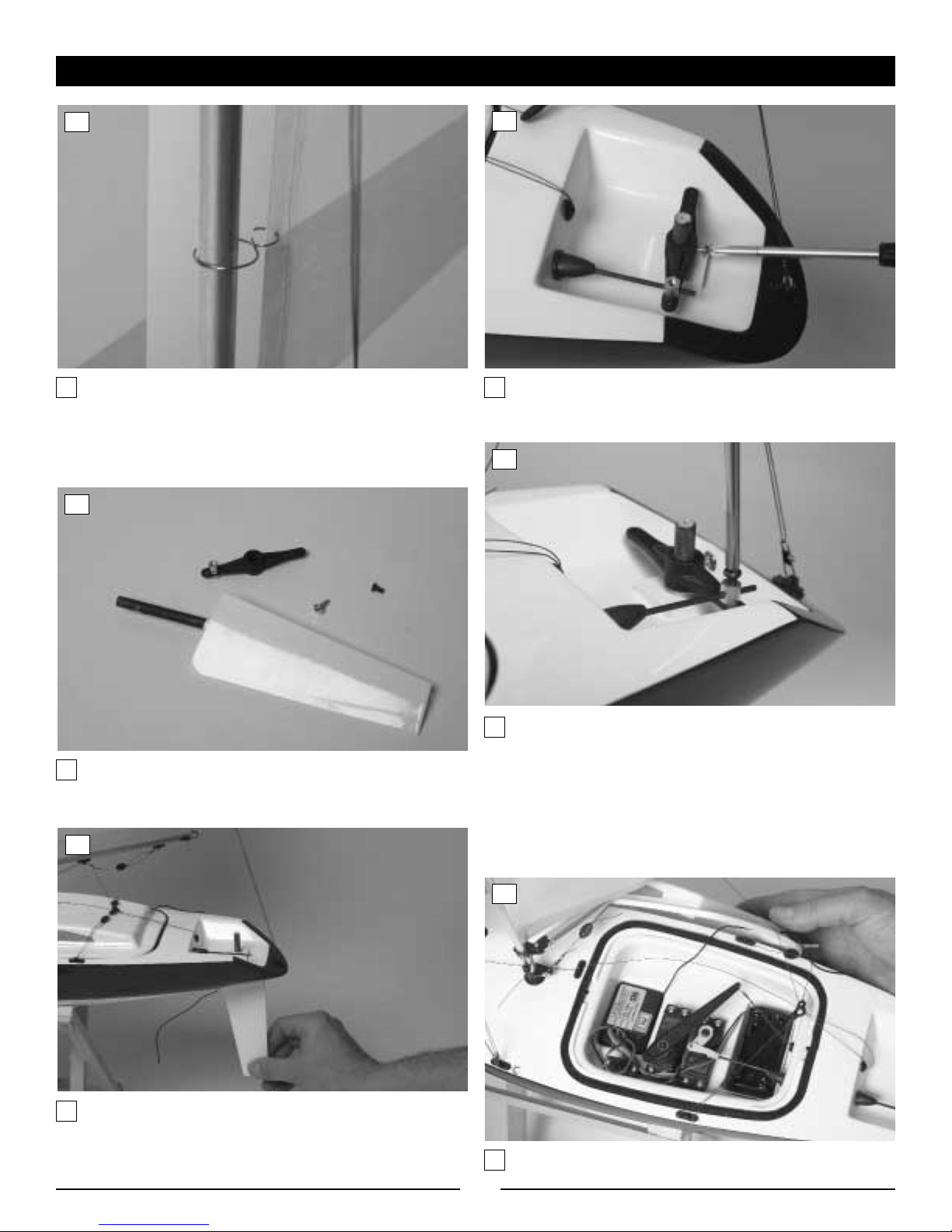
Using the ruler on page 15, begin at the top of the main sail
and measure 3" down. Mark that spot on the sail between the
seam on the right and the left edge. Make four more marks that
are exactly 7" apart down from the initial mark.
Secure the luft rings on the
sail as shown.
Use a hobby knife, sharp
tweezers, or small drill bit to
carefully make the holes where
you have just marked the sail.
Section 2—Completing the Boat (continued)
26
27
28
29
30 31
Cleat
3''
7''
7''
7''
7''
8
Make certain that each of the rings are attached as shown.
Locate the rudder and hardware to attach rudder.
Insert the rudder into the hull from the bottom as shown.
Attach the rudder arm onto the rudder as shown. Secure the
rudder with the included screw.
Secure the EZ connector to the pushrod by inserting and
tightening the screw as shown.
Note: Once the radio system is turned on, it may be necessary
to center the rudder servo. This is done by turning the radio
system on, loosening the EZ connector screw, allowing the
rudder to be re-centered, and re-tightening the screw with the
rudder in that position.
View of radio box with radio system installed
Section 2—Completing the Boat (continued)
32
33
34
35
36
37

9
Install 8 "AA" alkaline batteries into the radio transmitter
following the instructions for your radio system. Carefully
place the sailboat hull into the included boat stand if it is not
already on the stand. Next, carefully remove the radio box lid
(scale cockpit) of the boat. Care must be taken when doing this
as the cockpit is secured by a rubber band. Locate the receiver
battery box. Install 4 "AA" alkaline batteries into the battery box.
Return the battery box back into the allotted space.
After you have finished completing the boat, turn on the radio
system and test to make certain that it is functioning correctly.
First turn on the transmitter. Next, turn on the switch that
controls the receiver.
• By moving the right stick of your transmitter, you will control
the rudder. If you want to turn to the right, simply move the
stick to the right, and the rudder should also move to the right.
Do the opposite to turn left.
• By moving the left stick of your transmitter, you will control the
sails. By moving the left stick upward, you will let the sails out.
By pulling the left stick down, you will tighten the sails.
• When you have finished sailing, turn the receiver off before
turning the transmitter off.
• Always extend the transmitter antenna prior to sailing.
• Make certain that the receiver antenna is completely uncoiled.
• If the radio system works correctly and you are certain that
each sail and fitting is properly adjusted, you are ready to sail.
Section 3—Installation of Batteries for Radio Transmitter and Receiver
Section 4—Checking the Radio System
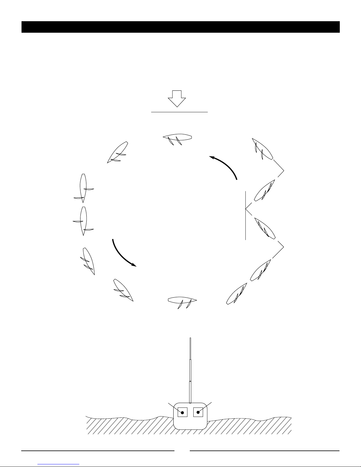
The following may help you get started in sailing. Follow the
instructions and understand that it takes some practice to
become an accomplished yachtsman.
Do not sail if the winds are too strong. Best results will occur
with winds between 5 and 12 mph.
Section 5—Sailing Tips
WIND
PORT TACK
NO SAIL ZONE
PORT
TACK
STARBOARD
TACK
STARBOARD TACK
CLOSE-HAULED
CLOSE-HAULED
WIND ABEAM
45°
45°
WIND ABEAM
QUARTER LEE
QUARTER LEE
RUNNING
10
Section 5—Sailing Tips (continued)
STARBOARD TACK
PORT TACK
Port Tack—Close—Hauled
Sails: Keeping pulled in
Rudder: To be held at the center as
long as the sails do not shiver
Tacking
Sails: Keeping pulled in
Rudder: To the left
START
Wind Abeam
Sails: Each at a position of 45°
Rudder: In center position
Luffing Up
Sails: Pulling both in all the way
Rudder: To the left
Port Tack—Close—Hauled
Sails: Keeping pulled in
Rudder: To be held at the center as
long as the sails do not shiver
Starboard Tack—Close—Hauled
Sails: Keeping pulled in
Rudder: To be held at the center as
long as the sails do not shiver
Tacking
Sails: Keeping pulled in
Rudder: To the right
Tacking
Sails: Keeping pulled in
Rudder: To the left
Bearing Away
Sails: Let both out so as not to shiver
Rudder: To the left
Wind Abeam
Sails: Each at a position of 45°
Rudder: In center position
Quarter Lee
Sails: Letting both out a little more
Rudder: To the left
Starboard Tack—Running
Sails: Letting both out to
their maximum position
Rudder: In center position
Port Tack—Running
Sails: Letting both out to
their maximum position
Rudder: In center position
Quarter Lee
Sails: Pulling both in a little
Rudder: In center position
Luffing Up
Sails: Pulling in bit by bit
Rudder: To the left
45°
WIND
Rudder Control
Sails Control
Starboard Tack and Port Tack

11
Beam Reach: Sailing at approximately 90 degrees to the wind
source with the wind coming from abeam
Beating: Sailing toward the wind source or against the wind
with the sails pulled in all the way, tacking as you go, to reach
a destination upwind
Boom: The horizontal spar to which the foot of a sail is attached
Bow: The forward end of a boat
Cleat: A fitting to which the rigging line may be secured
Downwind: Sailing away from the wind with the sails let out
all the way
Knot: One nautical mile per hour, one knot equals 1.2 mph
Main sail: The largest working sail that is attached to
the mast
Mast: Vertical spar to which the rigging and sails are attached
Port: The left side of the boat (when facing forward)
Rudder: Vertical plate attached at the stern that controls the
movements of the boat
Starboard: The right side of the boat (when facing forward)
Starboard Tack and Port Tack:
The right side of the boat is called the starboard side and the left
side is called port. When the boat sails with the wind coming
across the starboard side and the main sail is on the port side,
the boat is sailing on a starboard tack. When the boat sails with
the wind coming across the port side of the boat and the main
sail on the starboard side, the boat is sailing on a port tack.
Stern: The back end of a boat
Tack: To turn the bow of a sailboat through the wind so that the
sails fill the opposite side
Weather Helm: The natural tendency of a boat to turn toward
the wind
Basic Glossary

12
Replacement parts are available at your local hobby retailer.
PRB2172 Replacement Hull with Radio Box
PRB2173 Main and Jib Sails
PRB2174 ABS Cockpit
PRB2175 Rudder
PRB2176 Rudder Arm
PRB2177 Two-Piece Mast
PRB2178 Complete Plastic Parts Set
PRB2179 Rudder Pushrod
PRB2180 Rigging Line (10 meters)
PRB2181 Push Rod EZ Connector
PRB2182 Rubber Boot
PRB2183 Rigging Line Clips (10)
PRB2184 Boat Stand
PRB2185 Hull Fitting Screws (40)
PRB2186 Sail Luft Rings (6)
PRB2187 Rudder Pushrod Clevis
PRB2188 Sail Boom Screw and Eyelet
If you encounter any diffuculties with the Sunrise™24, please
contact the Horizon Service Center at 1-877-504-0233.
Replacement Parts
D
DC
C
E
I
Diagram of
Sail Rigging
13
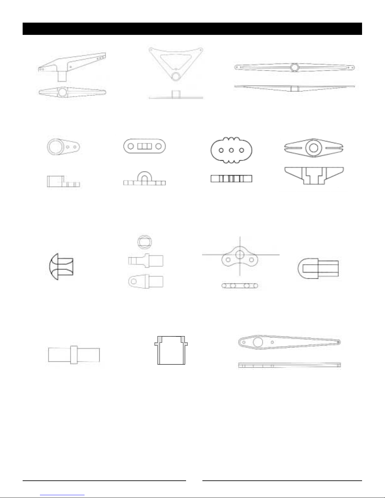
Sunrise Plastic Parts (PRB2178)
Masthead Crane
Gooseneck
(2 pcs.)
Eyeplate
(8 pcs.)
Jib Stay
(12 pcs.)
Cleat
(4 pcs.)
Rigging Line Grommets
(2 pcs.)
Boom Plugs
(3 pcs.)
Boom Pivot Rigging Line Eyelet
Sail Servo Arm
Spreader Spreader
Mast Joiner Mast Holder
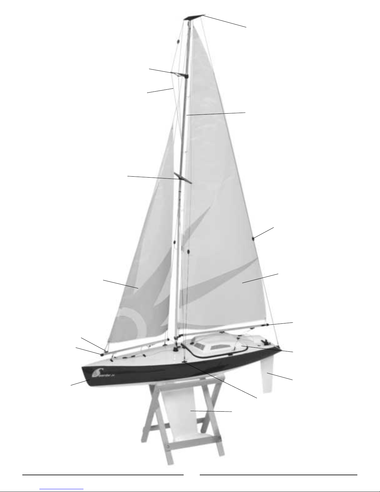
Crane
Jib Stay
Mast
Main Sail
Sail Boom
Cockpit
Rudder
Eyelet
Keel
Sail Boom
Hull
Jib Sail
Cleat
Lower Spreader
Top Spreader
Rigging Line
14

15
Notes
12345678910
cut here
✄

MADE IN CHINA
© Copyright 2002 Horizon Hobby, Inc.
www.horizonhobby.com
4132
Table of contents
Other Pro Boat Boat manuals

Pro Boat
Pro Boat Impulse 31 PRB08008 User manual

Pro Boat
Pro Boat ShockWave26 User manual

Pro Boat
Pro Boat Classic Runabout EP RTR User manual

Pro Boat
Pro Boat Jet Jam PRB08031 User manual

Pro Boat
Pro Boat ThunderCat 31 User manual

Pro Boat
Pro Boat Blackjack 24 User manual

Pro Boat
Pro Boat PRB08023 User manual
Popular Boat manuals by other brands


Jeanneau
Jeanneau SUN ODYSSEY 41 DS owner's manual

Meridian
Meridian 490 Pilothouse owner's manual

Advanced Elements
Advanced Elements AdvancedFrame Expedition AE1009 owner's manual

Robo Marine Indonesia
Robo Marine Indonesia GEOMAR user manual

Swallow Boats
Swallow Boats BayRaider owner's manual

X SHORE
X SHORE EELEX 8000 owner's manual


