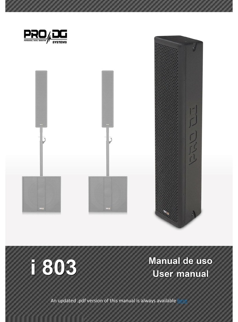
Pro DG Systems i 803 User manual

1
PRO DG SYSTEMS LE DA LAS GRACIAS POR ADQUIRIR ESTE SISTEMA
DE SONIDO PROFESIONAL TOTALMENTE DISEÑADO, ENSAMBLADO Y
OPTIMIZADO EN ESPANA Y LE DESEAMOS QUE DISFRUTE CON SU
ALTA CALIDAD Y PRESTACIONES.
El sistema ha sido diseñado, ensamblado y optimizado por Pro DG Systems
en un estado técnicamente perfecto. Para conservar este estado y asegurar
el correcto funcionamiento el usuario ha de respetar las siguientes
indicaciones y advertencias de este manual.
LA FIABILIDAD, SEGURIDAD Y RENDIMIENTO DEL SISTEMA ESTAN
UNICA Y EXCLUSIVAMENTE GARANTIZADAS POR PRO DG SYSTEMS
CUANDO:
• El montaje, manipulación, reajuste y los cambios o reparaciones hayan sido
realizados por Pro DG Systems.
• La instalación eléctrica cumpla con la determinación IEC (ANSI).
• El sistema se use según las indicaciones de uso.
ADVERTENCIA:
• Si se destapan protecciones o se retiran piezas del chasis, exceptuando las
que se puedan retirar manualmente, se pueden dejar piezas al descubierto
que sean conductoras de tensión.
• Cualquier ajuste, manipulación, optimización o reparación del sistema debe
ser realizada única y exclusivamente por Pro DG Systems. PRO DG
SYSTEMS NO SE RESPONSABILIZA DE NINGUN DANO QUE SUFRA EL
SISTEMA A CAUSA DE UNA MANIPULACION, AJUSTE, OPTIMIZACION O
REPARACION REALIZADA POR PERSONAL NO AUTORIZADO POR PRO
DG SYSTEMS.
• Niveles elevados de intensidad de sonido pueden ser causa de daños
auditivos se debe evitar acercarse demasiado a altavoces que funcionen a
altos niveles, de to contrario se deben usar protecciones auditivas.
ACOMETIDA A LA RED:
• El sistema está fabricado para un funcionamiento continuo.
• La tensión de funcionamiento ajustada tiene que coincidir con la tensión de
la red del lugar.
• La conexión a la red eléctrica se efectuará con la fuente de alimentación o
cable de red que se entreguen con el sistema.
• Fuente de alimentación: una línea de conexión dañada no se puede
sustituir. La fuente de alimentación no se puede volver a poner en
funcionamiento.
• Evite una conexión de la red eléctrica a distribuidores con muchas tomas de
corriente.
• El enchufe para el suministro de corriente tiene que estar cerca del aparato
y ser de fácil acceso.
SITUACION:
• El sistema debe situarse en una superficie limpia y totalmente horizontal.
• El sistema no puede estar expuesto a ninguna sacudida o movimiento
durante su funcionamiento.
• Evite el contacto del sistema con el agua y superficies húmedas.
• Procure que el sistema disponga de la suficiente ventilación y no bloquee ni
tape ninguna abertura de ventilación.
• Evite la exposición directa con el sol, así como la proximidad a fuentes
emisoras de calor o radiación.
• Si el sistema sufre un cambio extremo de temperatura es posible que afecte
a su funcionamiento, antes de poner en marcha el sistema espere que éste
haya adquirido la temperatura ambiental.
PRO DG SYSTEMS GIVES YOU THANKS FOR ACQUIRE THIS
PROFESSIONAL SOUND SYSTEM FULLY DESIGNED,
ASSEMBLED AND OPTIMIZED IN SPAIN, WE WISH THAT YOU
ENJOY WITH ITS HIGH QUALITY AND PERFORMANCE.
• This system has been designed, fabricated and optimized by Pro DG
Systems in perfect working order. To maintain this condition and
ensure the right operation, the user must respect the following
indications and advices of this manual.
THE FIABILITY, SAFETY AND EFFICIENCY OF THE SYSTEM ARE
ONLY AND EXCLUSIVELY GUARANTEED BY PRO DG SYSTEMS
IF:
• Assembly, manipulation, re-adjustment and modifications or repairs
are carried out by Pro DG Systems.
• The electrical installation complies with the requirements of IEC
(ANSI).
• The system is used according to the use indications.
WARNING:
• If protectors are opened or sections of chassis are removed, except
where this can be done manually, live parts can become exposed.
• Any adjustment, manipulation, optimization or reparation of the
system must be done only and exclusively by Pro DG Systems. PRO
DG SYSTEMS IS NOT RESPONSIBLE OF ANY DAMAGE OF THE
SYSTEM CAUSED BY A MANIPULATION, ADJUSTMENT,
OPTIMIZATION OR REPARATION REALIZED BY
NO-AUTHORIZED PERSONAL BY PRO DG SYSTEMS
• High loudspeaker levels can cause hearing damage, it must avoid the
direct contact with loudspeakers operating at high levels, Dtherwise it
must use hearing protectors.
MAIN CONNECTION:
• The system is designed for continuous operation
• The set operating voltage must match the local mains supply voltage.
• The unit has to be connected to the main via the supplied power unit
or power cable.
• Power unit: never use a damaged connection lead. Any type of
damage must be fixed.
• Avoid connection to the mains supply in distributor boxes together
with several other power consumers.
• The plug socket for the power supply must be positioned near the
unit and must be easily accessible.
PLACE OF SITUATION:
• The system should stand only on a clean and totally horizontal
surface.
• The system must not be exposed to any type of vibration during its
operation.
• Avoid the contact with the water or wet surfaces. Do not place objects
containing liquid on the system.
• Procure that the system has sufficient ventilation and do not block or
cover any ventilation opening. Obstruct the ventilation may cause
overheating in the system.
• Avoid direct exposure to the sun, as well as proximity to sources of
heat or radiation.
• If the system undergoes an extreme change in temperature may
affect its operation, before starting the system hope it has reached
room temperature.
2
ACCESORIOS:
• El sistema no debe colocarse encima de ningún soporte inestable que
pueda causar daños personales o al sistema coloque el sistema solo en un
carro, rack, tr(pode, soporte recomendado o suministrado por Pro DG
Systems siguiendo las indicaciones de instalación. El conjunto del sistema
con el pedestal se debe mover con mucho cuidado. La aplicación de una
fuerza desmesurada o un suelo irregular puede ocasionar la caída de todo el
conjunto.
• Piezas adicionales: no utilice nunca piezas adicionales que no estén
recomendadas por Pro DG Systems. El uso de piezas no recomendadas
puede provocar accidentes y rotura del sistema.
• Para proteger el sistema de una tormenta o si éste no se supervisa o utiliza
durante algún tiempo, se debe desconectar la clavija de la red. Así se evitan
daños en el sistema a causa de un rayo y golpes de tensión en la red de
corriente alterna.
SE RECOMIENDA AL USUARIO LEER ESTAS INSTRUCCIONES ANTES
DE USAR EL SISTEMA Y GUARDAR PARA SU USO POSTERIOR.
PRO DG SYSTEMS NO SE RESPONSABILIZA DEL USO INADECUADO
DEL SISTEMA POR PARTE DE PERSONAL NO AUTORIZADO SIN LOS
SUFICIENTES CONOCIMIENTOS DE USO.
EL USO DE LOS PRODUCTOS PRO DG SYSTEMS ESTA INDICADO PARA
LOS PROFESIONALES AUTORIZADOS QUE DEBEN POSEER LOS
SUFICIENTES CONOCIMIENTOS DE USO DEL MISMO Y SIEMPRE
RESPETANDO LAS INDICACIONES QUE SE MUESTRAN A
CONTINUACION EN ESTE MANUAL.
ACCESSORIES:
• Do not place the system on a unsteady base that can be cause of
damage to people or to the system, use it only with the trolley, rack,
tripod or base recommended or supplied by Pro DG Systems following
the installation indications. The system's combination must be moved
very carefully. The application of an excessive use of force and uneven
floors can cause the combination of system and stand to tip over.
• Additional equipment: don't use additional equipment wich has not be
recommended by Pro DG Systems. The use of not recommended
equipment can cause accidents and damage to the system.
• To protect the system during bad weather or when left unattended for
prolonged periods, the main plug should be disconnected. This
prevents the system being damaged by lightning and power surges in
the AC mains supply.
IT IS RECOMMENDED TO THE USER READ THESE
INSTRUCTIONS BEFORE USING THE SYSTEM AND SAVE FOR
LATER USE.
PRO DG SYSTEMS IS NOT RESPONSIBLE OF AN INADEQUATE
USE OF THE SYSTEM BY NO-AUTHORIZED PERSONNEL
WITHOUT ENOUGH KNOWLEDGE OF USE.
THE USE OF THE PRO DG SYSTEMS PRODUCTS IS INDICATED
FOR AUTHORIZED PROFESSIONALS THAT MUST TO HAVE
ENOUGH KNOWLEDGE OF THE SYSTEM USE AND ALWAYS
RESPECTING THE INDICATIONS SHOWED BELOW.
DESIGNED, ASSEMBLED AND OPTIMIZED IN SPAIN

3
Pro DG Systems i 803
Manual de usuario - User manual
Indice –Index.
Introducción / Introduction
- Descripción / Description ………………………………………………………………. Pag 4
- Especificaciones técnicas y arquitecturales / Technical
and arquitectural specifications ………...……………..…………………….……..…. Pag 5
Interior del i 803 / Inside i 803
- Características principales del transductor, Especificaciones
técnicas, Parámetros Thiele-Small, Información de montaje,
Curva de Impedancia, Respuesta de frecuencia ydistorsión /
Speaker key features, Technical specifications, Thiele-Small
parameters, Mounting information, Free air impedance curve,
Frequency response and distortion …………………………………..……….…… Pag 6-7
Hardware para instalación / Hardware for installation …………….... Pag 8-9-10

4
Introducción - Introduction
[ES] Este manual ha sido diseñado para ayudar a los usuarios del sistema i 803 de Pro DG Systems a la
correcta utilización y entendimiento de los beneficios y versatilidad del mismo. i 803 es un sistema
totalmente diseñado, ensamblado y optimizado en España.
[EN] This manual has been designed to help all the users of the system i 803 from Pro DG Systems to its
correct use as well as for the understanding of the benefits and versatility of the same. i 803 is a system
totally designed, assembled and optimized in Spain.
i 803
Totalmente diseñado, ensamblado y optimizado en España
Totally designed, assembled and optimized in Spain
Descripción - Description
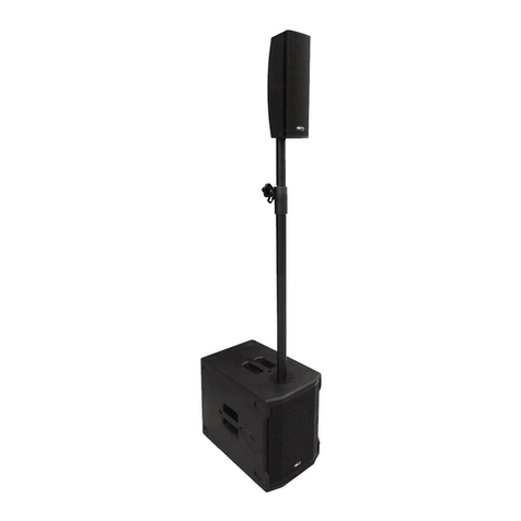
[ES] i 803 es un sistema tipo columna pasivo de 2 vías equipado con ocho altavoces de 2,75" en un recinto
sintonizado. El tamaño ultra compacto y la gran versatilidad de i 803 lo convierten en el sistema perfecto
para instalación permanente y todo tipo de aplicaciones de fuente puntual donde se requiere un discreto
impacto visual.
[EN] i 803 is a 2-way passive column-speaker equipped with eight (8) speakers of 2,75" in a tuned
enclosure. Its ultra-compact size and wide versatility makes it the perfect system for fixed installation and all
type of point source applications where an unobtrusive visual impact is required.

5
Especificaciones técnicas - Technical specifications
Power Handling: 280 W RMS (EIA 426A Standard) / 560 W program / 1120 W peak.
Nominal Impendence: 4 Ohm.
Average Sensitivity: 98 dB / 2.83V / 1m (average of 150-16.000Hz wideband).
Calculated Maximum SPL: / 1m 120 dB continuous / 123 dB program / 126 dB peak.
Frequency Range: +/- 3 dB from 170 Hz to 18 KHz
Nominal Directivity: 100º Horizontal.
Components: Eight (8) speakers of 2,75”, 8 Ohm, 35 W.
Subwoofer partner Cut-off: Together with subwoofer system IT 115 F:
25 Hz Butterworth 24 filter - 170 Hz Linkwitz-riley 24 filter.
Rigging Points: 4 x M5
Connectors: 2 NL4MP speakon connectors.
Acoustic Enclosure: CNC model, 12mm made from birch plywood plated on the exterior.
Finish: Standard finish in black paint of high weather resistance.
Cabinet Dimensions: (HxWxD) 740x130x125mm (29,13”x5,12”4,92”).
Weight: 7 Kg (15,43 lbs) net / 8 Kg (17,64 lbs) with packaging.
Especificaciones arquitecturales - Architectural specifications

6
Interior del i 803 -Inside i 803.
[ES] El interior del i 803 está compuesto por ocho altavoces Pro DG Systems de 2,75”, 35 W (RMS).
Especialmente diseñado bajo nuestros propios parámetros para el mejor rendimiento del sistema.
[EN] i 803 incorporates eight Pro DG Systems speakers of 2,75”, 35 W (RMS). Specially designed under
our own parameters for the best performance of the system.
2,75” full-range compact ferrite loudspeaker
35 W (RMS)
Extended response and low distortion
Paper cone and treated cloth surround
Steel basket
Ideal for beam-steering application (columns), portable
array and compact applications
Nominal diameter 70 mm (2,75 in)
Rated Impedance 8 Ω
Minimum impedance 6.5 Ω
Power capacity 35 W (RMS)
Program power 70 W
Sensitivity 91 dB 1W / 1m @ ZN
Frequency range 160 - 20.000 Hz
Voice coil diameter 20,3 mm (0.8 in)
Bl factor 4,9 N/A
Moving mass 0,0022 kg
Voice coil length 10,5 mm
Air gap height 3 mm
KEY FEATURES
TECHNICAL SPECIFICATIONS
Especialmente diseñado bajo nuestros propios
parámetros para el mejor rendimiento del sistema.
Specially designed under our own parameters for
the best performance of the system.

7
Resonant frequency, fs 160 Hz Overall diameter 93.5 mm (3.68 in)
D.C. Voice coil resistance, Re 5.6 ΩBolt circle diameter 85 mm (3,35 in)
Mechanical Quality Factor, Qms 8 Baffle cutout diameter:
Electrical Quality Factor, Qes 0,52 - Front mount 75.9 mm (2,98 in)
Total Quality Factor, Qts 0,49 Depth 46 mm (1.81 in)
Equivalent Air Volume to Cms, Vas 0679 l Net weight 0.57 kg (1,25 lb)
Mechanical Compliance, Cms 430 μm / N
Mechanical Resistance, Rms 0,28 kg / s
Efficiency, η0 0,5
Effective Surface Area, Sd 0,003 m2
Maximum Displacement, Xmax ** 4.5 mm
Displacement Volume, Vd 13.5 cm3
Voice Coil Inductance, Le @ 1 kHz 0.25 mH
THIELE-SMALL PARAMETERS*
MOUNTING INFORMATION
*T-S parameters are measured after an exercise period
using a preconditioning power test. The measurements are
carried out with a velocity-current laser transducer and will
reflect the long term parameters (once the loudspeaker
has been working for a short period of time).
** The Xmax is calculated as (Lvc - Hag)/2 + (Hag/3,5),
where Lvc is the voice coil length and Hag is the air gap
height.
FREE AIR IMPEDANCE CURVE
OFF-AXIS FREQUENCY RESPONSE
FREQUENCY RESPONSE AND DISTORTION
Note: On axis frequency response
measured with loudspeaker standing
on infinite baffle in anechoic chamber,
1W @ 1m

8
Hardware para instalación -Hardware for installation.
[ES] MUY IMPORTANTE: el uso incorrecto de los componentes puede ser motivo de la formación de grietas
que podrían poner en peligro la seguridad del sistema. El uso de componentes dañados podría dar lugar a
graves accidentes.
[EN] VERY IMPORTANT: a misuse of the components can be motive of cracking that could compromise the
safety of the system. Using damaged components could cause serious mishaps.
Trípode (OPCIONAL) -Tripod (OPTIONAL)
Material: Aluminio, recubierto de pintura negra.
Fijación en 5 pasos (17 cm cada paso),
incluye perno de seguridad.
Altura: 125 cm hasta 195 cm (49.21” -76.77”)
Carga Máxima: 25 Kg (55.11 lbs)
Diámetro tubo: 35mm (1.38 in)
Dimensiones (plegado): 1040x120x120mm (40.94x4.72x4.72 in)
-------------------------------------------------------------------------------------
Material: Aluminum,black powder coated 5 steps
(17 cm each step), includes safety bolt.
Height: 125 cm to 195 cm (49.21” -76.77”)
Max Load: 25 Kg (55.11 lbs)
Tube diameter: 35mm (1.38 in)
Folded dimensions: 1040x120x120mm (40.94x4.72x4.72 in)
Tubo roscado - Threaded tube
Material: Acero recubierto de pintura negra,
incluye perno de seguridad. Permite
estacar una unidad i 803 mediante
trípode o barra extensible.
Diámetro tubo: 36mm (1.42 in)
Dimensiones: 120x40x40mm (4.72x1.57x1.57 in)
-------------------------------------------------------------------------------------
Material: Steel, black powder coated, includes
safety bolt. It allows stacking one unit
i 803 using a tripod or extensible bar.
Tube diameter: 36mm (1.42 in)
Dimensions: 120x40x40mm (4.72x1.57x1.57 in)

9
Hardware para instalación - Hardware for installation.
Accesorio extensible con rosca (OPCIONAL) - Extensible accessory
with thread (OPTIONAL)
Material: Acero reforzado
Color: Negro.
Diámetro tubo: 35mm (1.38 in)
Altura: 840mm - 1120mm (33.07” -44.09”)
-------------------------------------------------------------------------------------
Material: Reinforced steel.
Colour: Black.
Tube diameter: 35mm (1.38 in)
Height: 840mm - 1120mm (33.07” -44.09”)
Accesorio extensible con manivela y sistema »Ring Lock« de König
& Meyer (OPCIONAL) - Distance rod with hand crank and »Ring
Lock« system from König & Meyer (OPTIONAL)
Material: Acero reforzado recubierto de pintura negra.
Extremo(s) del tubo: »Ring Lock« 35 hasta 37mm de diámetro perno
roscado M20.
Altura: 920mm - 1520mm / 36.22” - 59.84”
Peso: 3.86 Kg (8.51 lbs)
Características: Manivela con sistema de botón y tornillo de
seguridad. Diseño plegable de dos piezas.
Sistema de expansión patentado »Ring Lock«; conexión sin vibraciones
debido a férulas de plástico movibles; sistema de botón y manivela para
evitar el movimiento inverso incontrolado; tornillo de bloqueo para
seguridad adicional; perno de M20 para un ajuste preciso y vertical.
-------------------------------------------------------------------------------------
Material: Reinforced steel with black paint coated.
Tube end(s): Ring Lock diameter 35-37 mm, threaded bolt M20
Height: 920mm - 1520mm / 36.22” - 59.84”
Weight: 3.86 Kg (8.51 lbs)
Features: Hand crank with push-button system and locking
screw. 2-piece folding design.
Patented expanding mandrel system »Ring Lock«; vibration –free connect-
ion due to moveable plastic splints; push –button system and hand crank
avoid uncontrolled reverse motion; locking screw provides additional
safety; M20 bolt for precise and vertical fit.

10
Hardware para instalación - Hardware for installation.
Bracket de instalación en pared con poste de montaje de acero y angulación ajustable para soportar hasta 32
Kg (70.55 lbs) y 300mm (11.81 in) de longitud (OPCIONAL)
---------------------------------------------------------------------------------------------------------------------------------------------
Wall mount bracket with steel mounting pole and adjustable angulation to support up to 32 Kg (70.55 lbs) and
with a length of 300mm (11.81 in) (OPTIONAL)
Tenedor de montaje para dos unidades i 803 (OPCIONAL)
Mounting fork for two (2) units i 803 (OPTIONAL)
Material: Acero reforzado.
Perno de montaje: Diámetro 35x120mm (1.38x4.72 in)
Anchura: Ajustable de 310 a 490mm (12.20 - 19.29 in)
Carga Máxima: 2 x 32 Kg (2 x 70.55 lbs)
-------------------------------------------------------------------------------------
Material: Reinforced steel.
Mounting bolt: Diameter 35x120mm (1.38x4.72 in)
Width: Adjustable from 310 to 490mm (12.20 - 19.29 in)
Max Load: 2 x 32 Kg (2 x 70.55 lbs)
Cáncamo para instalación en pared o techo
(OPCIONAL) - Eyebolt for wall or ceiling
installation (OPTIONAL)
Hardware de integración para combinar hasta seis
unidades i 803 (OPCIONAL) - Integration hardware to
combine up to six units i 803 (OPTIONAL)
Other manuals for i 803
1
Table of contents
Languages:
Other Pro DG Systems Speakers manuals

Pro DG Systems
Pro DG Systems CMA-12BT User manual

Pro DG Systems
Pro DG Systems i 601 A User manual

Pro DG Systems
Pro DG Systems i 603 A User manual

Pro DG Systems
Pro DG Systems i 803 User manual

Pro DG Systems
Pro DG Systems G 2X12 L.A. User manual

Pro DG Systems
Pro DG Systems Neo 1 User manual

Pro DG Systems
Pro DG Systems IT-A 115 B User manual

Pro DG Systems
Pro DG Systems IT-A 112 PA User manual

Pro DG Systems
Pro DG Systems IT-A 118 B User manual