Pro-face PL-6930-T41 User manual

8VHU0DQXDO
3/3/6HULHV

1
Preface
Thank you very much for purchasing a Pro-face PL-6930/PL-7930 Unit, hereafter referred to as PL. PL is a general-pur-
pose computer for Factory Automation (FA), which accomplished high performance and the newest architecture with low
cost. Before using the PL, read this manual thoroughly to familiarize yourself with the PL’s operation procedures and
functions.
Product names used in this manual are the trademarks / registered trademarks of their respective owners.
© 2006 Digital Electronics Corporation. All rights reserved.
NOTICE
1. Copying this manual’s contents, either in whole or in part, is prohibited without the express permission of Digital
Electronics Corporation, Japan.
2. The information contained in this manual is subject to change without notice.
3. If you find any errors or omissions in this document, please contact Digital Electronics Corporation to report your
findings.
4. Regardless of Clause 3 above, Digital Electronics Corporation shall not be held responsible for any damage,
losses or third-party damage resulting from the use of this product.

2
Essential Safety Precautions
All safety-related procedures stated in this document must be followed to operate the PL correctly and safely. Be sure to
read this and any related documents thoroughly to understand the correct operation and functions of the PL unit.
Safety Icons
Throughout this manual, these icons provide essential safety information for PL operation procedures requiring special
attention. These icons indicate the following levels of danger:
System Design
Indicates situations where severe bodily injury, death or major equipment
damage can occur.
Indicates situations where slight bodily injury or minor equipment damage can
occur.
Indicates actions or procedures that should NOT be performed.
Indicates actions or procedures that MUST be performed to ensure correct
unit operation.
Do not create PL touch panel switches that could possibly endanger the safety of personnel or equipment.
A malfunction of the PL unit, its I/O unit(s), cable(s), or other related equipment can cause unexpected
output signals, leading to a serious accident. Be sure to design all important machine operation switches
so they are operated via a separate control system, and not via the PL.
Do not create PL touch panel switches to control machine safety operations, such as an emergency stop
switch. Install these switches as separate hardware switches, otherwise severe bodily injury or equipment
damage can occur.
Be sure to design your system so that a communication fault between the PL and its host controller will
not cause equipment to malfunction. This is to prevent any possibility of bodily injury or equipment dam-
age.
Do not use the PL as a warning device for critical alarms that can cause serious operator injury, machine
damage or can halt system operation. Critical alarm indicators and their control/activator units must be
designed using stand-alone hardware and/or mechanical interlocks.
Do not use the PL with aircraft control devices, aerospace equipment, central trunk data transmission
(communication) devices, nuclear power control devices, or medical life support equipment, due to these
devices’ inherent requirements of extremely high levels of safety and reliability.

3
Handling
Wiring
Maintenance
Be sure to use redundant and/or fail-safe system designs to ensure adequate levels of system reliability
and safety when using the PL with transportation vehicles (trains, cars and ships), disaster and crime pre-
vention devices, various types of safety equipment, non-life support related medical devices, and other
similar equipment.
After the PL unit’s backlight burns out the touch panel is still active, unlike the PL unit’s “Standby Mode”. If
the operator fails to notice that the backlight is burned out and touches the panel, a potentially dangerous
machine operation error can occur. Therefore, do not create PL unit touch panel switches that may cause
injury and/or equipment damage.
If your PL unit’s backlight suddenly turns OFF, use the following steps to determine if the backlight is actu-
ally burned out.
1) If the PL unit’s “Backlight Control” is not set and the screen has gone blank, your backlight is burned
out.
2) If the PL unit’s “Backlight Control” is set to Standby Mode and the screen has gone blank, and touching
the screen or performing another input operation does not cause the display to reappear, your backlight
is burned out.
Do not modify the PL unit. Doing so may cause a fire or an electric shock.
Do not operate the PL in an environment where flammable gases are present, since it may cause an
explosion.
To prevent an electric shock be sure to disconnect your PL unit’s power cord from the power supply before
wiring the PL.
Do not use voltage beyond the PL unit’s specified range. Doing so may cause a fire or an electric shock.
Do not connect or disconnect Host and PL unit communication cables while the PL is turned ON.
The PL uses a lithium battery for backing up its internal clock data and the battery may explode if it is
replaced incorrectly. When replacement is required, use a Pro-face-designated product.
SEE 8.6 Replacing the Internal Battery (page8-15)

4
Installation
Wiring
Maintenance
Unit Disposal
General Safety Precautions
Be sure all cable connectors are securely attached to the PL unit. A loose connection may cause incorrect
input or output signals.
Be sure to ground the PL unit’s FG wire separately from other equipment FG lines. Also, be sure to use a
grounding resistance of 100Ω or less and a 2mm2or thicker wire, or your country's applicable standard.
Otherwise, electric shock or malfunctions may result.
Be sure to use only the designated torque to tighten the PL unit’s terminal block screws. If these screws
are not tightened firmly, it may cause a short-circuit, fire or incorrect unit operation.
Be sure that metal particles and wiring debris do not fall inside the PL unit. They can cause a fire,
malfunction or incorrect unit operation.
Do not reset or turn the PL OFF, or insert or remove the hard disk or the CF Card while the PL unit’s CF
Card is being accessed. Otherwise, the data in the hard disk or CF Card may be damaged or lost.
When the product is disposed of, it should be done so according to your country’s regulations for similar
types of industrial waste.
Do not press on the PL unit’s display with excessive force or with a hard object, since it can damage the
display. Also, do not press on the touch panel with a pointed object, such as the tip of a mechanical pencil
or a screwdriver, since doing so can damage the touch panel.
Do not install the PL where the ambient temperature exceeds the specified range. Doing so may cause a
unit malfunction.
To prevent abnormally high temperatures from occurring inside the PL, do not restrict or block the PL
unit’s rear-face ventilation slots.
Do not operate the PL in areas where large, sudden temperature changes can occur. These changes can
cause condensation to form inside the PL, possibly causing it to malfunction.
Do not allow water, liquids or metal fragments to enter inside the PL unit’s case, since they can cause
either a malfunction or an electric shock. For use in Pollution Degree 2 environment.
Do not operate or store the PL in locations where it can be exposed to direct sunlight, high temperatures,
excessive dust, moisture or vibration.

5
LCD Panel Usage Precautions
• The LCD panel’s liquid contains an irritant. If the panel is damaged and any of this liquid contacts your skin,
immediately rinse the area with running water for at least 15 minutes. If the liquid gets in your eyes, immediately rinse
your eyes with running water for at least 15 minutes and consult a doctor.
• The PL unit’s LCD screen may show unevenness in the brightness of certain images or at some contrast settings. This
is an LCD characteristic and not a product defect.
• The PL unit’s LCD screen pixels may contain minute black and white-colored spots. This is an LCD characteristic and
not a product defect.
• The color displayed on the PL unit’s LCD screen may appear different when seen from outside the specified viewing
angle. This is an LCD characteristic and not a product defect.
• When the same image is displayed on the PL unit’s screen for a long period, an afterimage may appear when the image
is changed. If this happens, turn off the PL, wait 10 seconds and then restart the unit. This is an LCD characteristic and
not a product defect.
• To prevent an afterimage:
• Set the PL unit’s display OFF feature when you plan to display the same screen image for a long period of time.
• Change the screen image periodically and try to not display the same image for a long period of time.
Do not operate or store the PL where chemicals evaporate, or where chemicals are present in the air.
Corrosive chemicals : Acids, alkalines, liquids containing salt
Flammable chemicals : Organic Solvents
Do not use paint thinner or organic solvents to remove dirt or oil from the PL unit’s surface. Instead, use a
soft cloth moistened with a diluted neutral detergent.
Do not use or store the PL in areas with direct sunlight, since the sun's ultraviolet rays may cause the
LCD’s quality to deteriorate.
Do not store the PL in an area where the temperature is lower than that recommended in the PL unit’s
specifications. Doing so may cause the LCD display’s liquid to congeal, which can damage the LCD. Also,
if the storage area’s temperature becomes higher than the specified level, the LCD’s liquid may become
isotropic, causing irreversible damage to the LCD. Therefore, only store the PL in areas where tempera-
tures are within the PL unit’s specifications.
After turning OFF the PL, be sure to wait a few seconds before turning it ON again. The PL may not oper-
ate correctly if it is restarted too quickly.
Due to the possibility of unexpected accidents, be sure to back up the PL unit’s data regularly.
6
Information Symbols
This manual uses the following icons:
The Diagram for the PL Series Models
The type
P L ∗ 9 3 ∗ - T 4 ∗
A B C D E
Indicates a warning or a product limitation. Be sure to follow the instructions
given with this icon to ensure the safe operation of the PL.
Contains additional or useful information.
(1) (2) Indicates steps used to accomplish a given task.
Be sure to follow these steps in the order they are written.
*1 Indicates useful or important supplemental information.
Indicates pages containing related information.
PL-X930 Series Indicates a generic name for the products of PL-6930 and PL-7930.
A6 PL-6930 Series (12 inch type)
7 PL-7930 Series(15 inch type)
B04SlotType
12SlotType
C T TFT color LCD Type
D 4 CE Marking, UL/c-UL Approval
E
1Model without FAN
CPU: CeleronM 1.3GHz
2
Model attached FAN
CPU: PentiumM 1.6GHz, or
CeleronM 1.3GHz
(Embedded Optional Items)
SEE
7
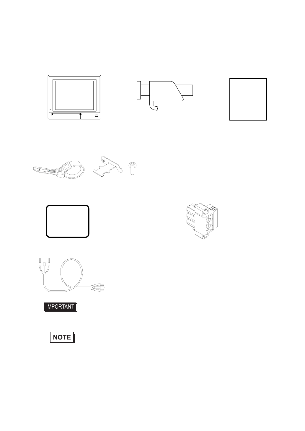
Package Contents
The following items are included in the PL unit’s package. Before using the PL, please check that all items listed below.
PL Unit (1) Installation Fasteners Installation Guide (1)
Protective Clamp (1 Set)
(The set includes Clamp(1),Bracket(1),Screw(1))
Installation Gasket (1) (Attachment Setting) Power Plug (1)
Power Cord (1)
This unit has been carefully packed, with special attention to quality. However, should you find anything damaged or
missing, please contact your local PL distributor immediately.
• The power cord for PL is designed only for AC100V use. Under other voltage
situation, you should use a different cord in conformity with the voltage.
• The power cord is exclusively for this product and it cannot be used for other
electric devices.
• If your PL unit contains a built-in accessory, that accessory’s Installation Guide will also
be included in the PL’s packing box. Please check that all items normally included with
that accessory are also included in this box.
4 / set x 2 for PL-6930 Series
4 / set x 3 for PL-7930 Series
(PL-6930/PL-6931/PL-7930/PL-7931)
Installation
Guide

8
Main Features
The PL-6930/PL-7930 series displays are equipped with the following features.
• The Latest, High-Performance Architecture
Designed around the Pentium®M (1.6GMHz) or Celeron®M (1.3GMHz) CPU, the PL utilizes the type of high
performance architecture that offers you superior compatibility. Add to this unrivalled support of the Windows®
XP and other widely used operating systems.
• High Expendability
PL supports expansion PCI/ISA bus. For the 4 slot type (PL-6930 and PL-7930) three slots are available for both
PCI bus and ISA bus. For the 2 slot type (PL-6931 and PL-7931) one slot is available for a PCI bus and two slots
are available for ISA bus.
• Bright LCD with a Wide Viewing Angle
The PL’s large TFT LCD display offers excellent visibility and brightness.
• High Resolution, Analog-Resistance-Film Touch Panel
Standard equipment with the PL is a high resolution 1024 x 1024 touch panel, and the mouse emulation utility
provides mouse-like functionality and pointer control.
• Easy Front Panel Installation
The PL is designed to be installed easily into the front of any panel or device. It is also rugged enough for use in
harsh, industrial environments, such as those found in the factory automation industries and provides protection
equivalent to the IP65f standard.
• Front-Access Port execution control function
This function can control some accesses from the access ports (USB port or reset switch) of the front face. This
operation prevents your important data from unwilling accesses, which may harm or destroy.
• Supporting USB2.0
USB2.0 supports USB High-speed devices.
• Pro-face’s top of the line TFT color LCD allows you to create detailed and powerful visual
images, with excellent brightness, a wide viewing angle, and a display capable of 64K colors.
SEE 1.1.2 Front Access Port Execution Control (page1-4)

9
UL Approval
PL6930-T4*, PL6931-T4*, PL7930-T4*, PL7931-T4* are UL/c-UL listed products (UL File No. E220851)
Those products conform to the following standards:
• UL508 Industrial Control Equipment
• CSA-C22.2 No.142-M1987 (c-UL Approval) Standard for Process Control Equipment
<Cautions>
Be aware of the following items when building the PL into an end-use product:
• The PL unit’s rear face is not approved as an enclosure. When building the PL unit into an end-use product, be sure to
use an enclosure that satisfies standards as the end-use product’s overall enclosure.
• For use on flat surface of a type 1 Enclosure.
• The PL unit must be used indoors only.
• Install and operate the PL with its front panel facing outwards.
• If the PL is mounted so as to cool itself naturally, be sure to install it in a vertical panel. Also, insure that the PL is
mounted at least 50 mm away from any other adjacent structures or machine parts. If these conditions are not met, the
heat generated by the PL unit's internal components may cause it to fail to meet UL standards.
CE Marking
PL6930-T4*, PL6931-T4*, PL7930-T4*, PL7931-T4* are CE marked products that conform to EMC compliant.
<Compliant Standards>
•Saftey
EN60950-1
•EMI
EN55011 ClassA, EN61000-3-2, EN61000-3-3
•EMS
EN61000-6-2
Product Model No. UL Registration Model No. Product Model No. UL Registration Model No.
PL6930-T41 3480901-01 PL7930-T41 3480901-05
PL6930-T42 3480901-02 PL7930-T42 3480901-06
PL6931-T41 3480901-03 PL7931-T41 3480901-07
PL6931-T42 3480901-04 PL7931-T42 3480901-08

10
Contents
Preface...................................................................................................................... 1
Essential Safety Precautions ................................................................................... 2
Information Symbols ................................................................................................ 6
The Diagram for the PL Series Models .................................................................... 6
Package Contents .................................................................................................... 7
Main Features .......................................................................................................... 8
UL Approval ............................................................................................................. 9
CE Marking .............................................................................................................. 9
Contents.................................................................................................................. 10
Chapter 1 Introduction
1.1 Prior to Operating the PL Unit.........................................................................1-2
1.1.1 Setting Up the Touch Panel Connection...............................................................1-3
1.1.2 Front Access Port Execution Control....................................................................1-4
1.1.3 Power Supply........................................................................................................1-5
1.2 System Design................................................................................................ 1-6
1.3 Accessories .................................................................................................... 1-7
1.4 Part Names and Functions............................................................................. 1-9
Chapter 2 Specifications
2.1 General Specifications.................................................................................... 2-2
2.1.1 PL-6930 Series General Specifications ................................................................2-2
2.1.2 PL-7930 Series General Specifications ................................................................2-4
2.2 Performance Specifications............................................................................ 2-6
2.2.1 PL-6930 Performance Specifications....................................................................2-6
2.2.2 PL-7930 Performance Specifications....................................................................2-9
2.3 Interface Specifications................................................................................. 2-12
2.3.1 Serial Interfaces (COM1/COM2/COM3/COM4)..................................................2-12
2.3.2 RAS Interface......................................................................................................2-14
2.4 Dimensions................................................................................................... 2-16
2.4.1 PL-6930 External Dimensions ............................................................................2-16
2.4.2 PL-6931 External Dimensions ............................................................................2-17
2.4.3 PL-7930 External Dimensions ............................................................................2-18
2.4.4 PL-7931 External Dimensions ............................................................................2-19
2.4.5 Dimensions attached RS-232C/RS-485 exchangeable unit ...............................2-20
2.4.6 Dimensions with a full-sized board cover............................................................2-22
2.4.7 Panel Cut Dimensions ........................................................................................2-24
2.4.8 Installation Fasteners..........................................................................................2-25

11
Chapter 3 Peripheral Device Installation
3.1 Installing optional units / expansion boards....................................................3-2
3.1.1 Uninstalling the Rear Maintenance Cover ............................................................3-2
3.1.2 Installing the Main Memory...................................................................................3-5
3.1.3 Uninstalling / Installing HDD units / CF card units.................................................3-6
3.1.4 Installing the Expansion board (PCI/ISA)..............................................................3-8
3.1.5 Connecting a CD-ROM drive unit .........................................................................3-9
3.2 Installing / Uninstalling PCMCIA Cards.........................................................3-15
3.3 Installing USB Cable Clamp..........................................................................3-16
Chapter 4 Installation and Wiring
4.1 Installing the PL unit........................................................................................4-2
4.1.1 Installation Procedures .........................................................................................4-2
4.2 Wiring..............................................................................................................4-7
4.2.1 Connecting the Power cord ..................................................................................4-7
4.2.2 Connecting the Power Supply ............................................................................4-10
4.2.3 Grounding Precaution.........................................................................................4-11
4.2.4 I/O Signal Line Placement Precaution................................................................4-11
Chapter 5 System Setup
5.1 Setup Procedures...........................................................................................5-2
5.2 System Parameters ........................................................................................5-3
5.2.1 Main......................................................................................................................5-3
5.2.2 Advanced..............................................................................................................5-6
5.2.3 Intel.....................................................................................................................5-19
5.2.4 Security...............................................................................................................5-30
5.2.5 Boot ....................................................................................................................5-31
5.2.6 Exit......................................................................................................................5-33
Chapter 6 Setting Up Software
6.1 Setting Up Your PL Unit..................................................................................6-2
6.1.1 Setting Up an HDD with no Pre-installed OS........................................................6-2
6.1.2 Setting Up an HDD with Pre-installed OS.............................................................6-4
6.2 Installing Drivers .............................................................................................6-6
6.3 Special Application Program Features............................................................6-8
6.3.1 Uninstalling PL-X930 Driver and Utility...............................................................6-10

12
6.4 Cautions When Using Windows®2000/Windows®XP...................................6-11
6.4.1 Automatic System Log-on Setup ........................................................................6-11
6.4.2 Using an Uninterrupted Power Supply................................................................6-11
6.4.3 When Changing the System Design...................................................................6-12
6.4.4 Changing to the NTFS File System ....................................................................6-12
Chapter 7 PL Monitoring Features
7.1 RAS Features................................................................................................. 7-2
7.1.1 RAS Features .......................................................................................................7-2
7.2 Monitoring the PL Status................................................................................. 7-8
7.2.1 Setup Procedures.................................................................................................7-8
7.2.2 Monitoring Operation ..........................................................................................7-10
7.2.3 Error Messages...................................................................................................7-12
7.3 Checking the Error Log List.......................................................................... 7-14
7.3.1 Error Message Display........................................................................................7-14
7.3.2 Error Type/Location and Error Action..................................................................7-15
7.4 Monitoring the PL Status from the Server.....................................................7-17
7.4.1 System Configuration..........................................................................................7-17
7.4.2 Setting Up the Client PL......................................................................................7-18
7.4.3 Setting Up the Server PC....................................................................................7-19
7.4.4 Reading/Writing the Status of the System Monitor/RAS Feature........................7-20
7.4.5 Restrictions.........................................................................................................7-24
7.5 Restarting/Shutting down the PL from the Server ........................................ 7-26
Chapter 8 Maintenance
8.1 Cleaning the Display....................................................................................... 8-2
8.2 Cleaning the Fan Filter ................................................................................... 8-3
8.3 Periodic Inspection Items................................................................................ 8-4
8.4 Replacing the Installation Gasket................................................................... 8-5
8.5 Replacing the Backlight.................................................................................. 8-7
8.5.1 Procedure for replacing the backlight of PL-6930 Series......................................8-8
8.5.2 Procedure for replacing the backlight of PL-7930 Series....................................8-11
8.6 Replacing the Internal Battery ...................................................................... 8-15
Appendices
1 I/O Map...........................................................................................................A-2
2 Memory Map...................................................................................................A-3
3 Interrupt Map ..................................................................................................A-4
4 Consent Agreement........................................................................................A-5


PL-6930 / PL-7930 Series User Manual
1-2
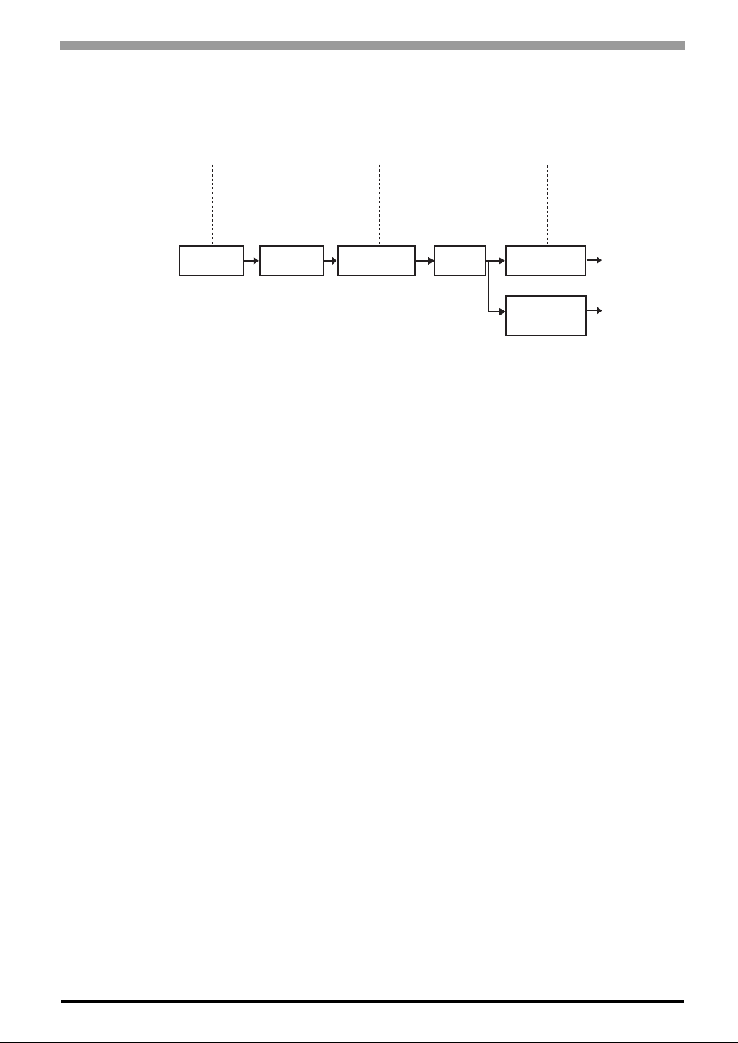
1.1 Prior to Operating the PL Unit
The following procedures are prior to use the PL unit.
• After hardware setup is completed, the OS (Windows®2000, Windows®XP) must
be used to create partitions and format (initialize) the HDD before any data or
applications can be saved to the hard disk drive. For details concerning these
procedures, refer to the OS manufacturer's instruction manual.
• Whenever you turn the PL unit's power OFF, wait until the internal HDD stops
spinning (approximately 5 seconds) before turning the power ON again.
• The PL’s hard disk is designed for use with the Windows®2000, Windows®XP.
This driver software can’t be applied to other operating systems.
Connect the display unit and any optional devices.
Connect the PL unit's power cord to AC Intercon-
nection and turn the power switch ON.
Configure the PL unit's BIOS.
Setup an OS for the PL.
Visit the download page at the Otasuke Pro! site.
URL http://www.pro-face.com/otasuke/
Setup the pre-installed PL.
Install all required software. For software instal-
lation instructions, refer to the manual provided
with that product.
SEE 1.2 System Design (page1-6)/1.3
Accessories (page1-7)
SEE 4.2 Wiring (page4-7)
SEE 5.1 Setup Procedures (page5-2)
SEE 6.1.1 Setting Up an HDD with no
Pre-installed OS (page6-2)
SEE 6.1.2 Setting Up an HDD with Pre-
installed OS (page6-4)
Connect Peripheral Devices
Connect Power
Set Up the System
Install an OS
Download and install the neces-
sary divers and utility software
Install Required Software
Install the PL Unit
[When PL has no preinstalled OS]
Install a commercial
OS in your PL. For
how to setup the OS,
refer to the manual
provided with the
product.
[When PL has preinstalled OS]

Chapter 1 Introduction
1-3
1.1.1 Setting Up the Touch Panel Connection
The connection method used can be via either a serial (RS-232C) or USB interface. Depending on the type of
Touch Panel connection used, the OS types that can be used will vary.
Touch Panel Changeover Switch
The switch changes the switch placed on the board inside of the unit to a state of COM4.
See the following for the place of the chageover switch.
Mouse Emulation Software
When installing the Mouse Emulation Software, be sure to select Serial communication (COM4).
SEE 1.4 Part Names and Functions (page1-9)

PL-6930 / PL-7930 Series User Manual
1-4
1.1.2 Front Access Port Execution Control
When you open the front maintenance hatch of the front unit, there are USB ports and a reset switch. If you
want to prevent unwilling or unintentional accesses, change the DipSW settings not to be executed some
accesses from reset from the front side or the USB ports.
See the following for the place of the DipSW.
DipSW
For the factory default settings; SW No.1 is ON, the others are OFF.
SEE 1.4 Part Names and Functions (page1-9)
SW No. Meaning ON OFF Notes
1Sets up an enabled/disabled
state for the front USB*1 port
execution control function
*1 The Setting up an enabled/Disabled state for USB port execution control function is avail-
able for only Windows®2000 and Windows®XP. Make sure to disable the function of the set-
ting when other OS used.
Enabled Disabled
The front USB port is available
when the SW is ON. It is
unavailable when the SW is
OFF.
2 Used for the system Reserved Reserved Do not change the initial
setting.
3Sets up an output of the USB
control signals(RAS DOUT2) if
needed.
Output
mode for
UPS
Shutdown
Normal
Output
RAS DOUT2 is the only for the
UPS control output when the
SW is ON. In that case, RAS
OUT2 cannot be used for
normal output.
4Implements the logical
inversion operation for RAS
output
Normal
Close Normal
Open
RAS output is a CLOSE state
when the SW and the system
is ON. When the SW is OFF, it
is the opposite.
The RAS Output keeps
Normal OPEN when the Soft
OFF*2 state occurs or the
power turns OFF.
5
Set up an enabled/disabled
state for the port execution
control function of the front
reset switch.
Disabled Enabled
The hardware switch is
unavailable when the SW is
ON. But, it is available to enter
switch from the Soft OFF*2
state.
*2 The Soft OFF refers to the state that Windows®has been shut down and the power is pro-
vided only for the electric circuit to boot system. This Soft OFF State is different from what
is System Standby set by Windows®. For the state of Soft OFF, see the following.
6Used for the system. Reserved Reserved Do not change the initial
setting.
7
8
SEE 1.1.3 Power Supply (page1-5)
Chapter 1 Introduction
1-5
1.1.3 Power Supply
About states of PL’s power supply, there are three(3) kinds of states, which are No Energization, Active State
(Normal), and Soft OFF State*1. Each state is outlined in the following.
*1 The Soft OFF refers to the state that Windows®has been shut down and the power is provided only for
the electric circuit to boot system. This Soft OFF State is different from what is System Standby set by
Windows®.
Power State :
Screen of PL :
Power LED :
No Energization
OFF
OFF
Active State (Normal)
ON
Green Lighting
Soft OFF
OFF
Green Blinking
PL’s
power On
PL’s system
activated
Shut down by
Windows program
System
Stop
Reset Switch ON
Power Switch OFF,
Remove Power
Cable
for Normal State
for No Energization
State

PL-6930 / PL-7930 Series User Manual
1-6
1.2 System Design
The following diagram illustrates the standard range of items that can be connected to the unit.
*1 The Pro-face’s optional devices used with PL.
*2 When using the HDD unit with the CD-ROM drive unit at the same time, be sure to set the HDD unit’s
setting as Master. [Chapter 3 Uninstalling / Installing HDD units / CF card units (page3-6).]
*3 The CARD BUS doesn’t include functions of ZOOMED VIDEO, SOUND.
• This diagram shows only the PL's internal layout and connectable devices. The user's actual
design may differ.
RAS I/F
(D-sub 25pin)
(4SLOT type :3 PORT,2SLOT type :1 PORT)
PCI/ISA SLOT
RS-232C/RS-485 Converting Unit *1
(Available only for COM2 / COM3)
ISA board (commercial type)
PCI board (commercial type)
DIM Module *1
Hub
(commercial type) Graphic Operation Panel for GP series
(Commercial or Conventional products)
(4SLOT type :3 PORT,2SLOT type :1 PORT)
MEMORY SLOTx1
200pin SODIMM
RAS Cable
(Produces by users)
RS232C I/F COM1.2.3.4
(D-sub 9pin)
USB I/F x 1 USB 2.0 or 1.1 Compatible Peripherals (commercial type)
USB 2.0 or 1.1 Compatible Peripherals
USB Keyboard on the narkef
Sound Devices such as Speaker
Pin- jack Cable
(commercial type)
IDE I/F
Secondary
LAN I/F x 2
(100/10BASE-T)
Primary (HDD0)
Secondary (HDD1)
PCMCIA
/CARD BUS *3 x 1
HDD/CF Card
Unit I/F x 2
USB I/F x 2
SOUND
(LINE IN.MIC.SPK)
HDD Unit or CF Card Unit *1 *2
Serial Cable
(commercial type)
CD-ROM Drive Unit *1
Twisted Pair Cable
(commercial type)
Commercial Item
Major
Network
Peripherals
(commercial type)
Back of PL unit
Side of PL unit
Front of PL unit
HDD Unit *1

Chapter 1 Introduction
1-7
1.3 Accessories
All accessories listed here are produced by Digital Electronics Corporation.
Optional Items
Product Name Model No. Description
DIM Module Memory PSA-DDR512 DIM module 512M Bytes
PSA-DDR1G DIM module 1G Bytes
CD-ROM Drive Unit PSS-CD01 IDE (ATAPI) compatible CD-ROM drive unit
(Connection cable is included with CD-
ROM unit)
CF Card Unit PL-CF200 Designed exclusively for 5V type cards.
Hard Disk Unit PL-HD240 HDD Unit mounted a Type 2.5 Hard Disk
The capacity is 40G byte and it doesn’t
include OS.
Full Sized Board Cover PL-FC200 Used when ISA full-sized expansion board
is used. (Used only with PL-6931/PL-7931.)
PL-FC210 Used when ISA full-sized expansion board
is used. (Used only with PL-6930/PL-7930)
RS-232C/RS-485
Converting Unit PL-RC500 RS232C - a converting unit for
RS485.When used, it should be placed on
COM2 or COM3.
Screen Protection Sheet PL-CS100 Disposable sheet that protects the PL unit’s
screen and prevents from dust.
(5 sheets/set) (Hard type)
CF Card
CA3-CFCALL/128MB-0* TYPE 1 128M byte
CA3-CFCALL/256MB-0* TYPE 1 256M byte
CA3-CFCALL/512MB-0* TYPE 1 512M byte
CA6-CFCALL/1GB-01 TYPE 1 1G byte
• Since the PL unit's hard disk drive (HDD) is a consumable item, i.e. it has a
limited lifetime, be sure to back up its data regularly and prepare a spare HDD
unit.
• The Hard Disk lifetime given here may be reduced due to unforeseen
environmental factors.The disk will be available until either of the following
conditions comes first. One is it spends 20,000 energization hours, the other is it
reaches 5 years. Those conditions are under at a condition of the surrounding
temperature 20 °C. The use condition and its environment will affect the lifetime
span.
This manual suits for next models
7
Table of contents
Other Pro-face Desktop manuals


