Pro-face PS-3701A User manual

Compact Panel Computer
PS-3701A
(EdenTM
ESP6000-667MHzModel)
User Manual

1
Introduction
The PS-3701A (Eden™ ESP6000 - 667MHz Model) (PS-A) of Compact Panel Computers are multipurpose factory auto-
mation (FA) computers, which embody Pro-face’s latest, cost-effective architecture. Before using the PS-A, read this
manual thoroughly to familiarize yourself with the PS-A’s operation procedures and functions.
Product names used in this manual are the trademarks of their respective manufacturers.
©Copyright 2003 Digital Electronics Corporation. All rights reserved.
NOTE
1. It is forbidden to copy the contents of this manual in whole, or in part, without the permission of the Digital Elec-
tronics Corporation.
2. The information in this manual is subject to change without notice.
3. This manual was written with care; however, if you should find any error or omissions, please contact Digital
Electronics Corporation and inform them of your findings.
4. Regardless of the above clause, Digital Electronics Corporation shall not be held responsible for any damages or
third-party claims for damages or losses resulting from the use of this product.

2
Essential Safety Precautions
This manual includes the following cautions concerning procedures that must be followed to operate the PS-A correctly
and safely. Prior to operating the PS-A, be sure to read this manual and any related materials thoroughly to understand the
correct operation and functions of this unit.
Safety Icons
To allow you to use the PS-A correctly, throughout this manual, the following icons are provided next to operations
requiring special attention. These icons are used to describe the following situations:
Failure to fully comply with points indicated by this symbol may result in death or
serious injury.
Failure to fully comply with points indicated by this symbol may result in injury or
equipment damage.
Indicates actions or procedures that should NOT be performed.
Indicates actions or procedures that MUST be performed to ensure proper opera-
tion.
To avoid the possibility of an electric shock, be sure to disconnect the power cord to the PS-A before con-
necting it to the main power supply.
A fire or electrical shock may occur if voltages used with the PS-A are beyond the specified range. Be
sure to use only the specified voltage.
Before opening the PS-A’s protective cover, be sure to turn the unit's power OFF. This is because the PS-
A's internal parts carry high voltages.
To avoid fires or electrical hazards, do not modify the PS-A in any way.
Do not create touch panel switches that are used to either control or to ensure the safety of equipment
and personnel. Mechanical switches, such as an emergency stop switch, a deadman (two-handed) start
switch, etc., must be installed and operated via a separate control system.
Do not create touch panel switches which could possibly endanger the safety of humans and equipment.
This is due to the possibility of a malfunction in the PS-A or its cable(s), causing the output of a signal that
could result in a major accident. All of a system's major, safety-related switches should be designed to be
operated separately from the PS-A.

3
After the PS-A’s backlight burns out, unlike the PS-A’s “Standby Mode”, the touch panel is still active. If the
operator fails to notice that the backlight is burned out and touches the panel, a potentially dangerous
machine miss-operation can occur.
If your PS-A’s backlight suddenly turns OFF, use the following steps to determine if the backlight is actu-
ally burned out.
1) If your PS-A is not set to “Standby Mode” and the screen has gone blank, your backlight is burned out.
2) Or, if your PS-A is set to Standby Mode, but touching the screen does not cause the display to reap-
pear, your backlight is burned out.
If metal particles, water or other types of liquids contact any of the PS-A’s internal parts, immediately turn
the unit’s power OFF, unplug the power cord, and contact either your PS-A distributor or the Digital Elec-
tronics Corporation.
Read and understand Chapter 2 “Hardware Installation” thoroughly in order to select an appropriate instal-
lation location for the PS-A.
Before either plugging in or unplugging interface connector, be sure to turn the PS-A’s power OFF.
To prevent a possible explosion, do not install the PS-A in areas containing flammable gases.
The PS-A is not appropriate for use with aircraft control devices, aerospace equipment, central trunk data
transmission (communication) devices, nuclear power control devices, or medical life support equipment,
due to these devicesí inherent requirements of extremely high levels of safety and reliability.
When using the PS-A with transportation vehicles (trains, cars and ships), disaster and crime prevention
devices, various types of safety equipment, non-life support related medical devices, etc. redundant and/
or fail-safe system designs should be used to ensure the proper degree of reliability and safety.
Do not push on the PS-A’s screen too strongly, with either your finger or with a hard object. Excessive
pressure can scratch, crack or damage the screen. Also, do not use a pointed object, such as a mechan-
ical pencil or screwdriver, to press any of the touch panel's switches, since they can damage the display.
If the screen becomes dirty or smudged, moisten a soft cloth with diluted neutral detergent, wring the cloth
well, and wipe the display. Do not use thinner or organic solvents.
Avoid exposing the PS-A to, or operating the PS-A in direct sunlight, high temperatures and humidity, and
in areas where excessive dust and vibration will occur.
Avoid using the PS-A in areas where sudden, extreme changes in temperature can occur. This may cause
condensation to form inside the unit, possibly leading to an accident.
To prevent the PS-A from overheating, be sure its air circulation vents are clear and clean, and keep the
unit's operation area well-ventilated.
Avoid operating or storing the PS-A near chemicals, or where chemicals can come into contact with the
unit.

4
LCD Usage and Handling
• The PS-A’s LCD contains a strong irritant. If the panel is ever cracked and the LCD’s liquid contacts your skin, be sure
to wash it with running water for at least 15 minutes. If any of this liquid should enter your eye, be sure to flush your
eye with running water for more than 15 minutes and see a doctor as soon as possible.
• The brightness of the LCD screen will depend on the screen's current display and the LCD’s contrast adjustment. Any
brightness variations that result are normal for LCD displays.
• There are minute grid-points (Dark or Light points) on the LCD surface. These points are not defects and are a part of
the PS-A unit's design.
• The displayed color will look different when viewed from an angle outside the specified view angle. This is also nor-
mal.
• When installing this unit, be sure that the screen is viewable from within the designated viewing angles. The screen
image being difficult to see from outside its recommended viewing angle is normal.
• Displaying a single screen image for long periods of time can cause an afterimage to remain on the screen. To correct
this, turn the unit OFF for 5 to 10 minutes, then ON again. This phenomenon is a common attribute of LCD displays,
and is not a defect. To prevent this effect, you can:
1) Use the Display OFF feature; if the same image is to be displayed for a long period of time.
2) Change the screen display periodically to prevent the displaying of a single image for a long period of time.
When PS-A Hard Disk (HDD) data is lost:
The Digital Electronics Corporation cannot be held responsible or provide any compensation for dam-
age(s) caused by the loss of data stored in the PS-A’s hard disk drive (HDD). It is therefore strongly sug-
gested that all important data and software be backed up regularly to an external data backup device.
Please be aware that the Digital Electronics Corporation bears no responsibility for any damages resulting
from the customer's application of this unit's hardware or software.
Since the PS-A unit’s hard disk drive (HDD) is a consumable item, i.e. it has a limited lifetime, be sure to
back up its data regularly and prepare a spare Hard Disk Drive (HDD) unit.
In order to extend the lifetime of the hard disk, Pro-face recommends you set the Windows [Control
panel]-[Power Management option]-[Turn off hard disks] selection to turn the hard disk off when the unit is
not being operated. A setting of 5 minutes is recommended.
To prevent file data damage, be sure to shut down the PS-A's OS before turning OFF the main power.
After turning OFF the PS-A’s power, wait until the internal hard disk drive (HDD) stops spinning before
turning on the power again (approx. 5 seconds).

5
Information Symbols
This manual uses the following icons:
Indicates a warning or a product limitation. Be sure to follow the instructions given with
this icon to insure the safe operation of the PS-A.
Contains additional or useful information.
*Indicates terms or items that require further explanation. See the footnote on that page.
Indicates pages containing related information.
(1) (2) Indicates steps used to accomplish a given task.
Be sure to follow these steps in the order they are written.
PS-A Refers collectively to the Compact Panel Computers PS-3701A (Eden™ ESP6000 -
667MHz Model) units.
SEE
6
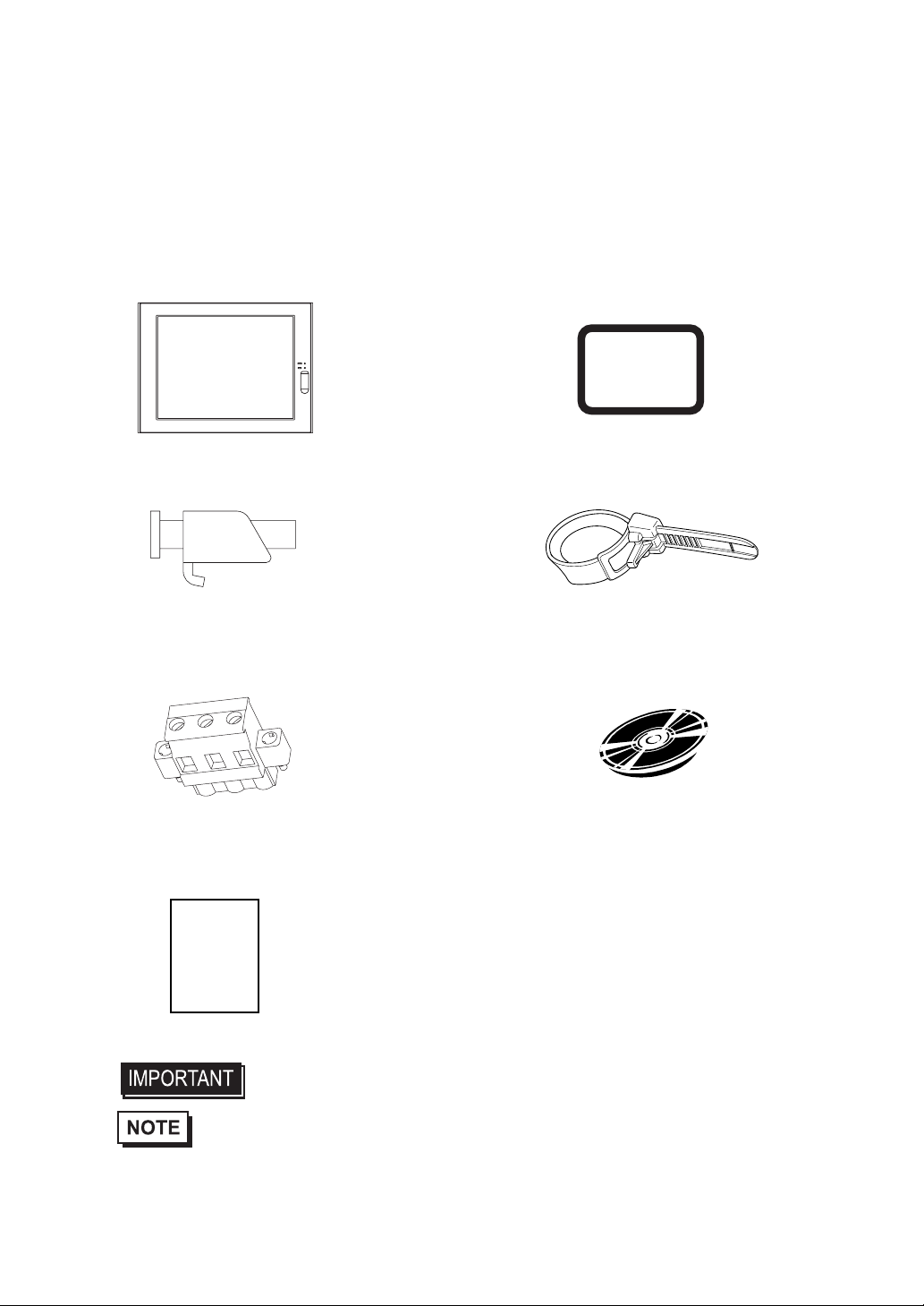
Package Contents
The following items are included in the PS-A’s package. Before using the PS-A, please confirm that all items listed here
are present.
PS-A
(PS3701A-T41-DU-E66) Moisture Resistant Gasket (1)
Installation Fasteners (4/set x 2) USB Cable Clamp (2)
CD-ROM (1)
Power Plugg (1) PS370XA-E66 User Manual & Driver CD
Installation Guide (1)
(Japanese/English)
• Be careful when installing the PS-A not to damage the built-in HDD.
• The CD-ROM included in this package contains a User Manual, RAS-API Reference
Manual, and PS-A Series Utility and Driver files.
Installation
Guide

7
This unit has been carefully packed, with special attention to quality. However, should you find anything
damaged or missing, please contact your local PS-A distributor immediately.
When you order a PS-A unit built to your specifications, that PS-A package should include each optional
item's Installation Guide. Please use that guide to check the contents of each optional item's package.

8
UL/c-UL (CSA) Application Notes
PS3701A-T41-DU-E66 unit is UL/c-UL listed product (UL File No. E220851). Please pay special attention to the follow-
ing instructions when applying for UL/c-UL approval for machinery which includes any of PS-A units.
The PS-A conforms as a component to the following standards:
UL508 Industrial Control Equipment
CAN Std C22.2 No.14-1995 CAN/CSA22.2 No.6.950
PS3701A-T41-DU-E66 (UL Registration Model No.:3280022-01)
- Equipment with a PS-A unit mounted in it requires UL/c-UL evaluation for the combination of the PS-A and equip-
ment.
- The PS-A must be used as a built-in component of an end-use product.
- Use the PS-A indoors only.
- When connecting the PS-A’s power cord, be sure to use a cord that is appropriate for the current and voltage used and
that has conductive wires that are AWG18 or larger.
- When using the PS-A in an end-use product, be sure to install the PS-A unit’s power cut-off switch where the operator
can easily reach it.
- Danger of explosion if backup battery is incorrectly replaced. Should be replaced only with same or equivalent type
recommended by the manufacturer. Dispose of used batteries according to the manufacturer’s instructions.
- Be sure the unit the PS-A is built into uses a UL508 compatible structure.

9
CE Marking Notes
PS3701A-T41-DU-E66 unit is CE marked, EMC compliant product.
<Complies with the following Standards>
Safety
EN60950
EMI
EN61000-6-4, EN55011(Group 1, Class A)
EMS (EN61000-6-2/EN61131-2)
EN61000-4-2, EN61000-4-3, EN61000-4-4, EN61000-4-5, EN61000-4-6, EN61000-4-8, EN61000-4-12
FCC
47CFR Part 15 Class A
If the following requirements are not met, the PS-A may fail to meet EN60950 standard requirements.
• The PS-A must be used as a built-in component of an end-use product.
• Use the PS-A indoors only.
• When connecting the PS-A’s power cord, be sure to use a cord that is appropriate for the current and voltage used and
that has conductive wires that are AWG18 or larger.
• When using the PS-A in an end-use product, be sure to install the PS-A unit’s power cut-off switch where the operator
can easily reach it.
• There is a danger of explosion if the backup battery is incorrectly replaced. This battery should be replaced only with
same or equivalent type recommended by the manufacturer. Dispose of used batteries according to the manufacturer’s
instructions.
• Be sure the PS-A unit’s enclosure is an EN60950 approved sheet steel structure.

10
Memo

11
Table of Contents
Introduction................................................................................................................ 1
Essential Safety Precautions..................................................................................... 2
Information Symbols.................................................................................................. 5
Package Contents..................................................................................................... 6
UL/c-UL (CSA) Application Notes............................................................................. 8
CE Marking Notes..................................................................................................... 9
CHAPTER 1 Overview
1.1 Prior to Operating the PS-A Unit.....................................................................1-2
1.2 PS-A Unit System Configuration.....................................................................1-3
1.2.1 Using the USB Interface (located on the front face) .............................................1-4
1.3 PS-A Unit Part Names and Features..............................................................1-5
1.4 Interfaces........................................................................................................1-7
1.4.1 Serial Interface (COM1/COM2).............................................................................1-7
1.4.2 Printer Interface (LPT1) ......................................................................................1-12
1.5 PS-A Unit External Views and Dimensions...................................................1-13
1.5.1 PS-A Unit............................................................................................................1-13
1.5.2 External Dimensions (with Installation Fasteners installed)................................1-13
1.5.3 Panel Cut Dimensions ........................................................................................1-14
1.5.4 Installation Fasteners..........................................................................................1-14
CHAPTER 2 Hardware Installation
2.1 Installation.......................................................................................................2-2
2.1.1 Removing the PS-A Unit's Cover..........................................................................2-2
2.1.2 PS-A Internal View................................................................................................2-3
2.1.3 Main Memory Installation......................................................................................2-3
2.1.4 PCMCIA Unit Installation ......................................................................................2-4
2.1.5 USB Cable Clamp Installation...............................................................................2-5
2.1.6 CF Card Installation and Removal........................................................................2-7
2.2 Installing the PS-A Unit...................................................................................2-9
2.2.1 Installation Caution ...............................................................................................2-9
2.2.2 Installation Procedures .......................................................................................2-11
2.3 Wiring the PS-A ............................................................................................2-15
2.3.1 Connecting the Power Cord................................................................................2-15
2.3.2 Power Supply Cautions ......................................................................................2-16
2.3.3 Grounding Cautions............................................................................................2-18
2.3.4 Cautions When Connecting I/O Signal Lines......................................................2-18

12
CHAPTER 3 System Setup
3.1 Setup Procedures........................................................................................... 3-2
3.2 System Parameters........................................................................................ 3-3
3.2.1 Standard CMOS Features.....................................................................................3-3
3.2.2 IDE HDD Auto-Detection ......................................................................................3-5
3.2.3 Advanced BIOS Features.....................................................................................3-6
3.2.4 Advanced Chipset Features..................................................................................3-9
3.2.5 Integrated Peripherals.........................................................................................3-12
3.2.6 Power Management Setup .................................................................................3-16
3.2.7 PnP/PCI Configurations......................................................................................3-18
3.2.8 IRQ Resources ...................................................................................................3-19
3.2.9 System Monitor Setup.........................................................................................3-20
3.2.10 Frequency/Voltage Control ...............................................................................3-21
3.2.11 Load Fail-Safe Defaults.....................................................................................3-21
3.2.12 Load Optimized Defaults...................................................................................3-22
3.2.13 Set Supervisor Password..................................................................................3-22
3.2.14 Set User Password...........................................................................................3-22
3.2.15 Save & Exit Setup.............................................................................................3-22
3.2.16 Exit Without Saving...........................................................................................3-22
CHAPTER 4 Setting up Your PS-A Unit
4.1 CD-ROM Contents.......................................................................................... 4-2
4.1.1 Software................................................................................................................4-2
4.2 Setting Up Your PS-A Unit.............................................................................. 4-3
4.2.1 Setup Procedures.................................................................................................4-3
4.2.2 Setting Up an HDD with Pre-installed OS.............................................................4-4
4.3 Installing Drivers............................................................................................. 4-6
4.4 Special Application Program Features............................................................ 4-7
4.4.1 Uninstalling Utility Software ..................................................................................4-9
4.5 When Using Windows® 2000/Windows® XP...............................................4-10
4.5.1 Automatic System Log-on Setup ........................................................................4-10
4.5.2 Uninterrupted Power Supply System (UPS).......................................................4-11
4.5.3 Changing System Settings..................................................................................4-11
4.5.4 NTFS File System Conversion............................................................................4-11
CHAPTER 5 Monitoring Features
5.1 RAS Features................................................................................................. 5-2
5.1.1 PS-A RAS Features..............................................................................................5-2
5.1.2 RAS Feature Details.............................................................................................5-3
5.1.3 RAS Feature Overview.........................................................................................5-5

13
5.2 System Monitor/RAS Features.......................................................................5-6
5.2.1 Setup Procedures.................................................................................................5-6
5.2.2 System Monitoring Property Settings (PSA_Wps.exe).........................................5-7
5.2.3 System Monitoring Operation (PSA_Smon.exe)...................................................5-9
5.2.4 Error Messages ..................................................................................................5-12
5.3 Error Displays When Using Event Viewer.....................................................5-14
5.3.1 Error Message Display .......................................................................................5-14
5.3.2 Error Type/Location ............................................................................................5-15
5.3.3 Error Action.........................................................................................................5-15
5.4 Remote RAS.................................................................................................5-16
5.4.1 System Configuration .........................................................................................5-16
5.4.2 Installation Procedures .......................................................................................5-16
5.4.3 Setup and Preparation of the Remote RAS Feature...........................................5-17
5.4.4 Read and Write of the System Monitor/RAS Feature.........................................5-19
5.4.5 Restrictions.........................................................................................................5-22
5.5 Remote Shutdown Feature...........................................................................5-23
CHAPTER 6 Maintenance and Inspection
6.1 Regular Cleaning............................................................................................6-2
6.1.1 Cleaning the Display.............................................................................................6-2
6.1.2 Installation Gasket Replacement..........................................................................6-3
6.2 Changing the PS-A Backlight .........................................................................6-4
6.3 Periodic Inspection Items................................................................................6-7
CHAPTER 7 Specifications
7.1 General Specifications....................................................................................7-2
7.1.1 Electrical Specifications ........................................................................................7-2
7.1.2 Environmental Specifications................................................................................7-2
7.1.3 Structural Specifications........................................................................................7-4
7.2 Performance Specifications ............................................................................7-5
7.2.1 Performance Specifications ..................................................................................7-5
7.2.2 Display Functions .................................................................................................7-6
7.2.3 Clock Accuracy.....................................................................................................7-6
CHAPTER AppAppendices
A.1 Hardware Configuration..............................................................................App-2
A.1.1 I/O Map............................................................................................................ App-2
A.1.2 Memory Map ................................................................................................... App-3
A.1.3 Interrupt Map................................................................................................... App-4
A.2 List of Optional Devices..............................................................................App-5

14
Memo


Compact Panel Computer PS-3701A (Eden™ ESP6000 - 667MHz Model) User Manual
1-2
1.1 Prior to Operating the PS-A Unit
The following explanation shows the preparation steps required prior to operating the PS-A.
• After hardware setup is completed, the OS must be used to create partitions and
format (initialize) the HDD before any data or applications can be saved to the
hard disk drive. For details concerning these procedures, refer to the OS manu-
facturer's instruction manual.
• Whenever you turn the PS-A unit's power OFF, wait until the internal HDD stops
spinning (approximately 5 seconds) before turning the power ON again.
• The PS-A’s hard disk is designed for use with the Windows® 2000, Windows®
XP. Other operating systems do not support this driver software, etc.
Connect the display unit and any optional devices.
Connect the PS-A unit's power cord to AC Intercon-
nection and turn the power switch ON.
Configure the PS-A unit's BIOS.
Install all required software. For software instal-
lation instructions, refer to the manual provided
with that product.
SEE
1.2 PS-A Unit System Configuration
(page 1-3) /
1.3 PS-A Unit Part Names and Feature
s
(page 1-5)
SEE
2.3 Wiring the PS-A (page 2-15)
SEE
3 System Setup (page 3-1)
Connect Peripheral Devices
Connect Power
Set Up the System
Install an OS
Install PS370XA-E66
User Manual and Driver CD Data
Install Required Device Drivers
Install Required Software
Install the PS-A Unit
[When PS-A has no preinstalled OS]
Install a commercial OS
in your PS-A. For how to
setup the OS, refer to
the manual provided
with the product.
[When PS-A has preinstalled OS]

Chapter 1 Overview
1-3
1.2 PS-A Unit System Configuration
The following chart shows the range of peripheral items connected to the PS-A.
• This diagram shows only the PS-A’s internal layout and connectable devices. The
user’s actual design may differ.
P
S3701A-T41-DU-E66
Inside of PS-A uni
t
Bottom of PS-A unit
Side of PS-A unit
Front of PS-A unit
COM1/COM2
CF
IDE I/F
Printer I/F
Ethernet I/F
PCMCIA I/F
(2 ports)
Keyboard I/F
CD-ROM Drive
*1 Built-in accessory only
*2 Digital Electronics Corporation's optional devices and commercial products.
Please refer to A.2 List of Optional Devices.
USB I/f
(2 ports)
USB Connector
(1 ports)
CF Card Slots
(TYPE2, 1 port)
Speaker Out I/F
Hub
Speak
er
PS/2 Keyboard
Central Network Line
HDD Unit*1 *2
Main Momory Module*1 *2
CF Cards*2
CF Cards*2
Main Memory
Connector
Peripherals
(commercial type)
USB 1.1 Compatible Peripherals
(commercial type)
USB 1.1 Compatible Peripherals
(commercial type)
PCMCIA Card
(commercial type)
Pin-jack Cable
(commercial type)
Printer Cable
(commercial type)
10BASE-T/100BASE-TX
Cable (commercial type)
RS-232C Cable
Rear of PS-A unit
CD-ROM Drive Unit
PSS-CD01
CF
CF Card Adapter *2

Compact Panel Computer PS-3701A (Eden™ ESP6000 - 667MHz Model) User Manual
1-4
1.2.1 Using the USB Interface (located on the front face)
(Connection example)
• When using multiple commercial-type USB peripheral devices, be sure to use a
commercial-type USB HUB. However, USB HUBs cannot be connected to each
other.
Chapter 1 Overview
1-5
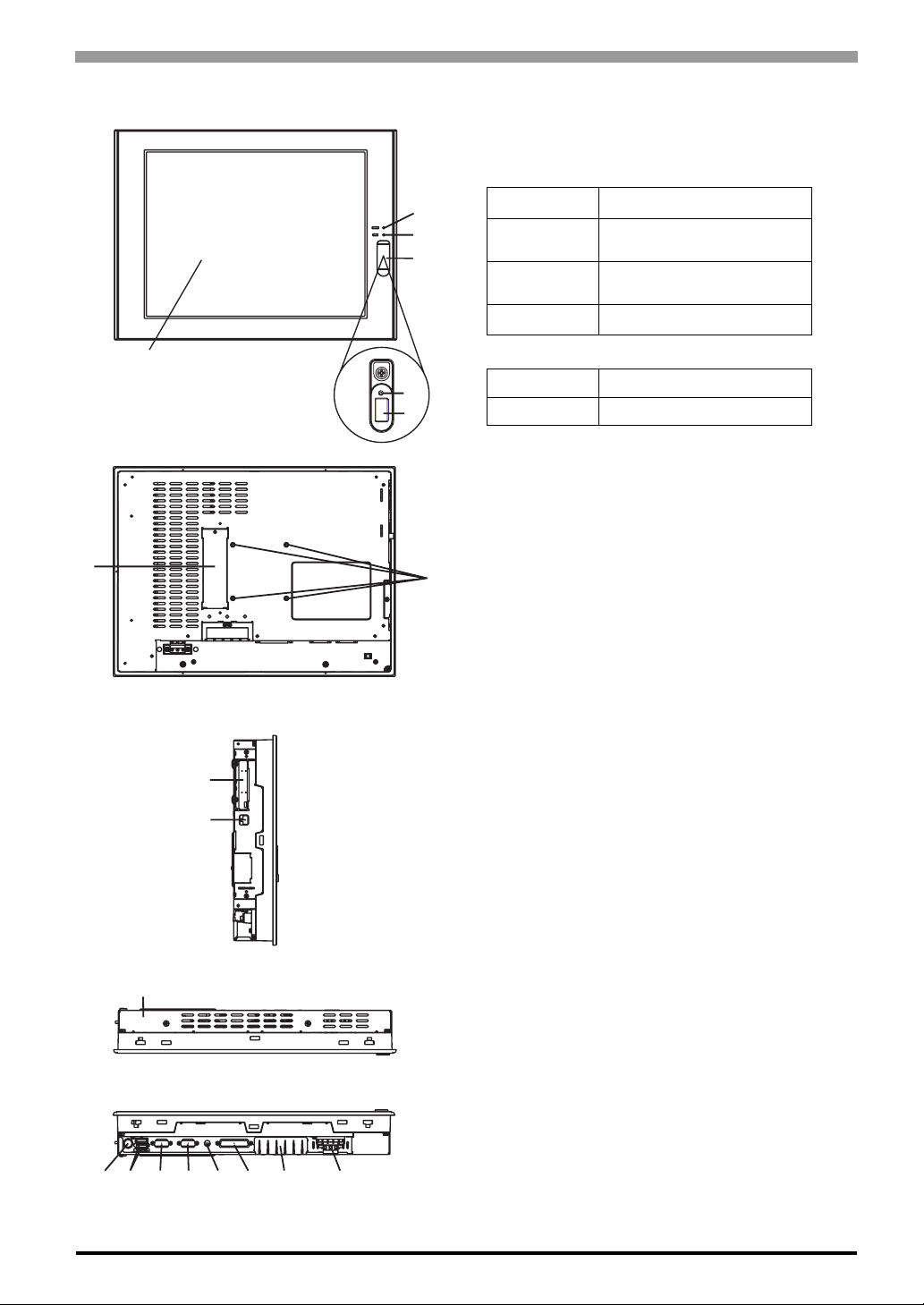
1.3 PS-A Unit Part Names and Features
Front
Rear
Left Side
Top
Bottom
2
3
4
15
6
78
9
10
11
12 13 14 15 16 17 18 19
1 : Display / Touch Panel
2 : Power Lamp LED (POWER)
3 : IDE Access Lamp
4 : Front Packing
5 : Hardware Reset Switch (RESET)
Pressing this switch re-starts the PS-A unit.
6 : USB Interface (1 port)
Provides a USB 1.1 compatible connection.
Connect a USB connectable device here.
7 : CD-ROM Drive Interface Cover
This cover is removed when installing optional CD-
ROM Drive unit (PSS-CD01).
8 : Arm Attachment Screw Holes (VESA 75mm)
9 : PCMCIA Interface (PCMCIA)(2 ports)
10 : Ethernet Interface
10 BASE-T /100 BASE-TX Auto Changeover
11 : Rear Cover
This cover is removed when installing an HDD unit,
main memory, or Expansion unit (PCI).
12 : Keyboard Connector (KEYBOARD)
Connect a PS/2-compatible keyboard here.
13 : USB Interface (2 ports)
Provides a USB 1.1 compatible connection.
Connect a USB connectable device here.
14 : Serial Interface (COM2)
[RS-232C/RS-422/RS-485 Changeover,
+5V/RI Changeover]
15 : Serial Interface (COM1)
[+5V/RI Changeover]
16 : Speaker Output Connector (SPEAKER OUT)
17 : Printer Connector (LPT1)
18 : CF Card Interface Cover
19 : Power Input Terminal Block
LED PS-A Status
Green Normal Operation
(Power On)
Orange System Monitor Error
Touch Panel Self Test Error
Orange/Red Backlight is not functioning
LED PS-A Status
Green Currently using IDE I/F
Table of contents
Other Pro-face Desktop manuals


