PFXZCETWHA
PFXZCETWW
PFXZCETWHA
PFXZCETWW
消費電力型式 電源電圧 段数 ブザー LED
有
3有
PFXZCETWHA
PFXZCETWW
82dB
85dB
55 32 131
2W
DC 5V
(USBバスパワー)
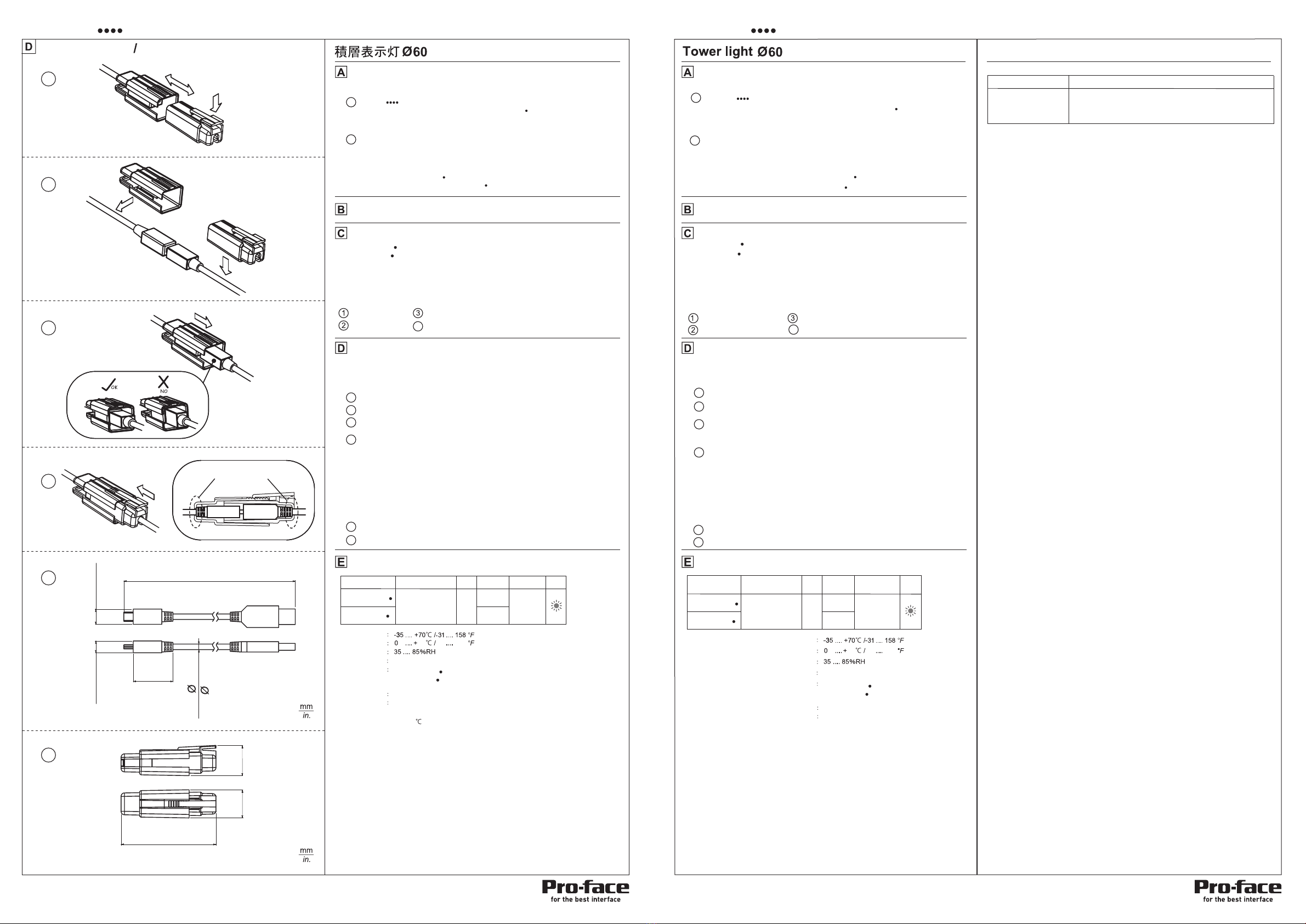
ケーブルロック取付方法
定格
梱包内容
取付方法
外観寸法図
USBケーブルの抜け防止のため、USBケーブル接続部に
本製品付属のケーブルロックを取り付けた状態で使用してください。
取付は、振動の少ない十分な強度のある平らな面を選んでください。
IP特性を維持するため、製品は図の通り取り付けてください。
・USBケーブル x1
・付属品 : M4フランジナット(セレート付) x3 (PFXZCETWW の場合)
・付属品 : 防水シート x1
・付属品 : ケーブルロック 1組
・M5なべ小ねじ x4 (PFXZCETWHA の場合)
下記部品は、別途ご用意ください。
PFXZCET 本体 1台
取扱説明書 1冊(本書)
本製品を設置する前に、パッケージに次のものが全てそろっているかどうかを確認してください。
ねじは、規定の本数を全てしっかりと固定してください。
・ケーブルロックがUSBケーブルに当たっていることを確認してください。
当たっていない場合、抜け止め性能が発揮できません。
・ケーブルロックは正しい方向で挿入してください。また、ケーブルロックがUSBケーブルに当たったら、
それ以上無理に押し込まないで下さい。
USBケーブル及びケーブルロックの破損の恐れがあります。
・本製品は必ず電圧と電流が制限された電源、またはUL60950に規定される有限電源をご使用ください。
(*1) 最大使用周囲温度: 55
(*2) IP54はUL認証には該当しません。
I/F仕様
コネクタ仕様
USB 2.0
保管温度
使用周囲温度 (*1)
使用周囲湿度
使用雰囲気 腐食性ガスのないこと
(結露のないこと)
保護特性
USBシリーズ Mini-Bプラグ(メス)
1
2
4
1
2
6
ケーブルロック取り付け手順●
●対応USBケーブル寸法(Aプラグ ー Mini-Bプラグ 長さ最大:4m)
●
ケーブルロック外観寸法図
5
タブを押さえてツメを上げ、ケーブルロックを分離させます。
各部寸法が、図の値の範囲内のUSBケーブルを使用してください。
フランジナット(セレート付)
引出しコード穴
ブザー開口部位置
防水シート
: 直付けタイプ
: 円形台座付 ポール取付けタイプ
本製品にUSBケーブルが接続された状態で、各ケーブルロックをUSBケーブルに通します。
3図のようにして、USBケーブル接続部をツメのないほうのケーブルロックに入れます。
・USBケーブル接続部の方向は、図の”OK”の方向にしてください。
図のようにケーブルロックを合体させ、ケーブルロックがUSBケーブルに当たるまで押し込ん
でください。
1
2
4
6
5
3
Max 4000
Max 118.1
Max 11.0
Min 9.0
Max 0.43
Min 0.35
Max 8.5
Min 5.6
Max 0.33
Min 0.22
Max 5.2
Max 0.20
Max 30.5
Min 23.3
Max 1.20
Min 0.92
Max 71.1
Min 63.9
Max 2.80
Min 2.52
21.9
0.86
20.4
0.80
3/4 4/4
( )
( )
( )
( )
( )
( )
( ) ( )
( )
( )
4
Mini-B type A type
CABLE LOCK INSTALLATION
SPECIFICATIONS
PACKAGE CONTENTS
INSTALLATION
DIMENSIONS
・M5フランジナット(セレート付) x4 (PFXZCETWHA の場合)
ケーブルロック取付方法 CABLE LOCK INSTALLATION
no gap no gap
: IP54 (*2)
: IP54 (*2)
Check whether all the followings are inside the package before installing this product.
PFXZCET body x 1
・Accessories:M4 Hexagon nut with flange x3 (PFXZCETWW )
・Accessories:Waterproof rubber seal x1
・Accessories:Cable lock x1
Instruction manual x1(This manual)
The following parts need to be prepared separately by customer.
・USB cable x1
・M5 pan head (machine) screw x4 (PFXZCETWHA )
・M5 Hexagon nut with flange x4 (PFXZCETWHA )
:TUBE MOUNTING WITH FIXING PLATE
:BASE MOUNTING
Choose a flat surface with enough strength and with little vibration for installation.
This product is designed for use on a flat surface of a Type 1 Enclosure.
Mount this product according to the figure to maintain IP characteristics.
Tighten all the required screws.
Cable outlet
Buzzer opening position
Waterproof rubber seal
Hexagon nut with flange
For prevention of the disconnection of the USB cable, use the USB cable with the
included cable lock installed on the joint.
Cable lock installation procedure
Hold the tab to raise the hook, and separate the cable lock.
With USB cable connected to XVGU product, put each cable lock on the USB
cable.
As shown in the figure, place USB cable joint into the section of the cable lock
with no hook.
・Direct the USB cable as shown under "OK" of the figure.
Connect the cable lock as shown in the figure and push the cable lock until it
touches the USB cable.
・Make sure that the cable lock is in contact with the USB cable.
If the cable is not inserted fully into cable lock, disconnection can occur.
・Insert the cable lock in the correct direction. In addition, stop pushing it when it
touches the USB cable.
・This product must be powered by LVLC or LPS (Limited power source, per UL 60950).
(*1) Maximum Surrounding Air Temperature Rating: 55°C
(*2) IP54 is not part of UL certification.
Damage to USB cable and the cable lock may result.
Maximimum USB cable dimensions(A plug ーMini-B plug Length maximum:4m)
Use USB cable with the dimensions within the values shown in the figure.
Figure of cable lock external dimensions
LED
3
82dB
85dB 2W
DC 5V
Part number Supply voltage Units Buzzer Power
consumption
(USB bus power)
YES
YES
Storage temperature
Operating ambient temperature range (*1)
Operating ambient humidity range
Operable atmosphere
Degree of protection
(no condensation)
No corrosive gas
I/F specification
Connector specification USB series Mini-B plug(female terminal)
2. Prepare supported screen editing software.
3. Create a screen in display application to control this product.
4. Refer to sample parts for the screen.
Refer to the following website for the details.
1
2
4
●
1
2
4
3
●
6
5
55 32 131
USB 2.0
●
誤った取付け方をした場合、水が入り、内部回路が破損する恐れがあります。
本製品は、タイプ1 エンクロージャの平面上に取り付けられるように設計されています。
Incorrect installation may allow water to enter, potentially resulting in damage to the
internal circuitry.
http://www.pro-face.com/otasuke/
1. Check for the supported equipment.
本製品は表示器からの専用制御コマンド(システム変数)を受信し動作します。
ご利用にあたり、以下の準備が必要です。
1. 対象機種の確認をしてください。
2. 対応する画面作成ソフトウェアを準備してください。
3. 本製品が制御できるように画面を作画してください。
4. 画面についてはサンプルパーツを参考にしてください。
作画方法とシステム変数についてはご使用の画面作成ソフトウェアのマニュアルを参照してください。
これらの詳細は下記のホームページを参照してください。
http://www.proface.co.jp/otasuke/
This product displays colors according the commmands (system variables)
received from the operator display.
To use this signal tower, the following preparations must be made.
For information about screen ceation and system variable setting,
please refer to the manual provided with your screen editing software.
사용자안내문
A급 기기
(업무용 방송통신기자재)
기 종 별
이 기기는 업무용(A급) 전자파적합기기로서 판매자 또는 사용자는
이 점을 주의하시기 바라며, 가정외의 지역에서 사용하는 것을 목적
으로 합니다.
기 종 별
PFXZCET PFXZCET
www.pro-face.com www.pro-face.com
PFXZCETWHA
PFXZCETWW
PFXZCETWHA
PFXZCETWW
: IP54 (*2)
: IP54 (*2)
PFXZCETWHA
PFXZCETWW
Copyright © 2013.11 Digital Electronics Corporation. All Rights Reserved.


