Pro Force VPF1080318 User manual

200-2705
E103525
Revision A
Operator-Parts Manual
Oilless, Single Stage, Direct Drive, Electric Air Compressors
200-2705 (E103525)_ Rev A_7-08
WARNING: Read and understand all safety precautions in this manual before operating. Failure to comply with
instructions in this manual could result in personal injury, property damage, and/or voiding of your warranty. The
manufacturer WILL NOT be liable for any damage because of failure to follow these instructions.
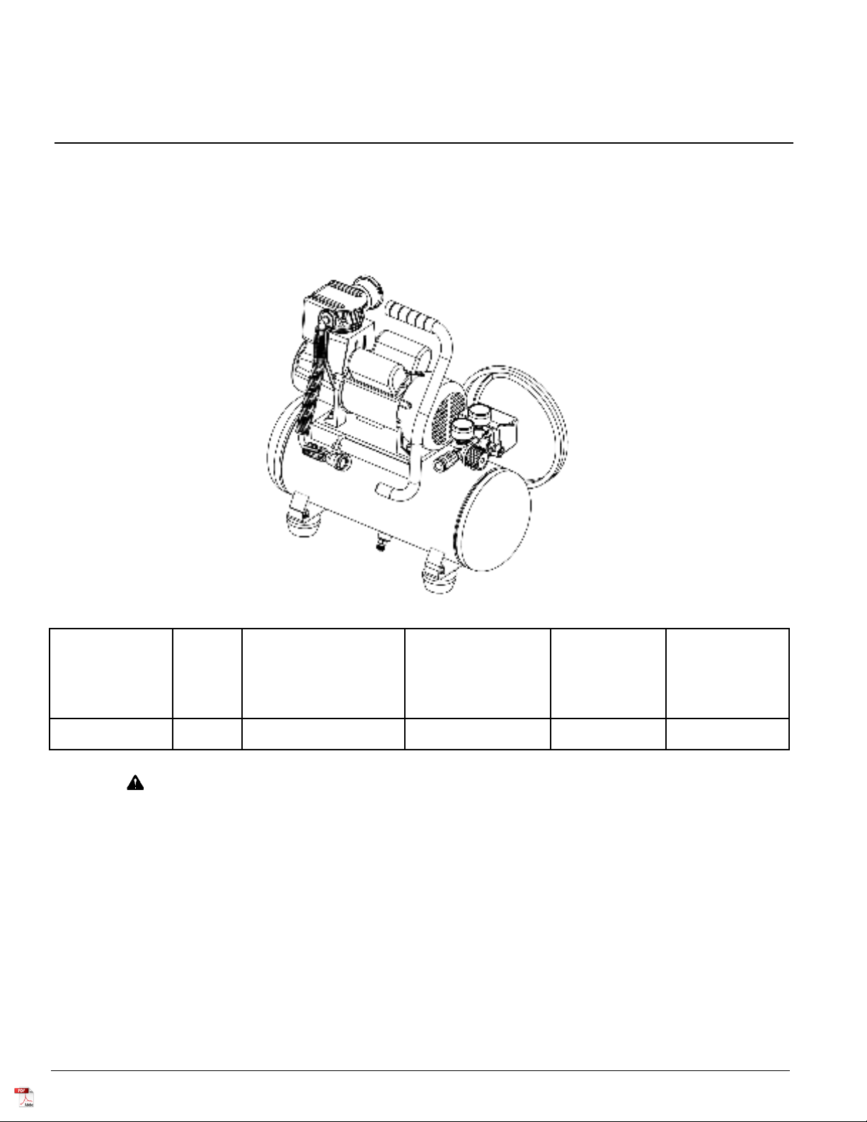
Specification Chart
Questions? See back page.
?
Product style and configuration may
vary.
MODEL NO. RUNNING
H.P.
(CV)
TANK CAPACITY
GALLONS
VOLTAGE/AMPS/
PHASE
KICK-IN
PRESSURE
KICK-OUT
PRESSURE
VPF1080318 1.0 3 (11,4) 120/12/1 95
(6,55 bar)
125
(8,62 bar)

200-27052
SAFETY GUIDELINES . . . . . . . . . . . . . . . . . . . . . . . . . . .3
OVERVIEW . . . . . . . . . . . . . . . . . . . . . . . . . . . . . . . . . . .6
Basic Air Compressor Components . . . . . . . . . . . . .6
ASSEMBLY . . . . . . . . . . . . . . . . . . . . . . . . . . . . . . . . . . .7
Assembling the Compressor . . . . . . . . . . . . . . . . . . .7
COMPRESSOR CONTROLS . . . . . . . . . . . . . . . . . . . . . .8
ELECTRICAL POWER REQUIREMENTS . . . . . . . . . . . .9
Electrical Wiring . . . . . . . . . . . . . . . . . . . . . . . . . . . . .9
Extension Cords . . . . . . . . . . . . . . . . . . . . . . . . . . . .9
Grounding Instructions . . . . . . . . . . . . . . . . . . . . . . .9
OPERATING INSTRUCTIONS . . . . . . . . . . . . . . . . . . . .11
Daily Startup . . . . . . . . . . . . . . . . . . . . . . . . . . . . . .11
Shutdown . . . . . . . . . . . . . . . . . . . . . . . . . . . . . . . . .11
MAINTENANCE . . . . . . . . . . . . . . . . . . . . . . . . . . .13 & 16
Draining the Tank . . . . . . . . . . . . . . . . . . . . . . . . . .13
Checking the Relief Valve . . . . . . . . . . . . . . . . . . . .16
Testing for Leaks . . . . . . . . . . . . . . . . . . . . . . . . . . .16
Storage . . . . . . . . . . . . . . . . . . . . . . . . . . . . . . . . . .16
Service interval . . . . . . . . . . . . . . . . . . . . . . . . . . . .16
PARTS LIST . . . . . . . . . . . . . . . . . . . . . . . . . . . . . . .14-15
TROUBLESHOOTING CHART . . . . . . . . . . . . . . . . . . .17
TABLE OF CONTENTS

200-2705 3
1. RISK OF FIRE OR EXPLOSION. Never spray
flammable liquids in a confined area. It is normal for
the motor and pressure switch to produce sparks
while operating. If sparks come into contact with
vapors from gasoline or other solvents, they may
ignite, causing fire or explosion. Always operate the
compressor in a well–ventilated area. Do not smoke
while spraying. Do not spray where sparks or flame
are present. Keep compressor as far from spray area
as possible.
2. RISK OF BURSTING. Rust can weaken the tank.
Drain the condensed water from the tank after each
use to reduce rusting. If a leak is detected in the tank,
replace the tank immediately. Do not weld, drill or
modify the air tank of this compressor. Welding or
modifications on the air compressor tank can severely
impair tank strength and cause an extremely
hazardous condition. Welding or modifying the tank in
any manner will void the warranty.
3. RISK OF ELECTRICAL SHOCK. A licensed
electrician in accordance with all local and national
codes must install all wiring. Never use an electric air
compressor outdoors when it is raining or on a wet
surface, as it may cause an electric shock.
4. RISK OF INJURY. This unit starts automatically.
ALWAYS shut off the compressor, remove the plug
from the outlet, and bleed all pressure from the
system before servicing the compressor, and when
the compressor is not in use. Do not use the unit with
the shrouds or beltguard removed. Serious injury
could occur from contact with moving parts.
5. RISK OF BURSTING. Check the manufacturer’s
maximum pressure rating for air tools and
accessories. Compressor outlet pressure must be
regulated so as to never exceed the maximum
pressure rating of the tool. Relieve all pressure
through the hose before attaching or removing
accessories.
6. RISK OF BURNS. High temperatures are generated
by the pump and manifold. To prevent burns or other
injuries, DO NOT touch the pump, manifold or
transfer tube while the pump is running. Allow them to
cool before handling or servicing. Keep children away
from the compressor at all times.
7. RISK TO BREATHING. Be certain to read all labels
when you are spraying paints or toxic materials, and
follow the safety instructions. Use a respirator mask if
there is a chance of inhaling anything you are
spraying. Read all instructions and be sure that your
respirator mask will protect you.
8. RISK OF EYE INJURY. Always wear ANSI Z87.1
approved safety goggles when using an air
compressor. Never point any nozzle or sprayer toward
a person or any part of the body. Equipment can
cause serious injury if the spray penetrates the skin.
9. RISK OF BURSTING. Do not adjust the pressure
switch or relief valve for any reason. Doing so voids
all warranties. They have been preset at the factory
for the maximum pressure of this unit. Personal injury
and/or property damage may result if the pressure
switch or the relief valve are tampered with.
10. RISK OF BURSTING. Do not use plastic or pvc pipe
for compressed air. Use only galvanized steel pipe
and fittings for compressed air distribution lines.
11. RISK TO HEARING. Always wear hearing protection
when using an air compressor. Failure to do so may
result in hearing loss.
12. RISK TO BREATHING. Never directly inhale the
compressed air produced by a compressor. It is not
suitable for breathing purposes.
13. The power cord on this product contains lead, a
chemical known to the State of California to cause
cancer, and birth defects or other reproductive harm.
Wash hands after handling.
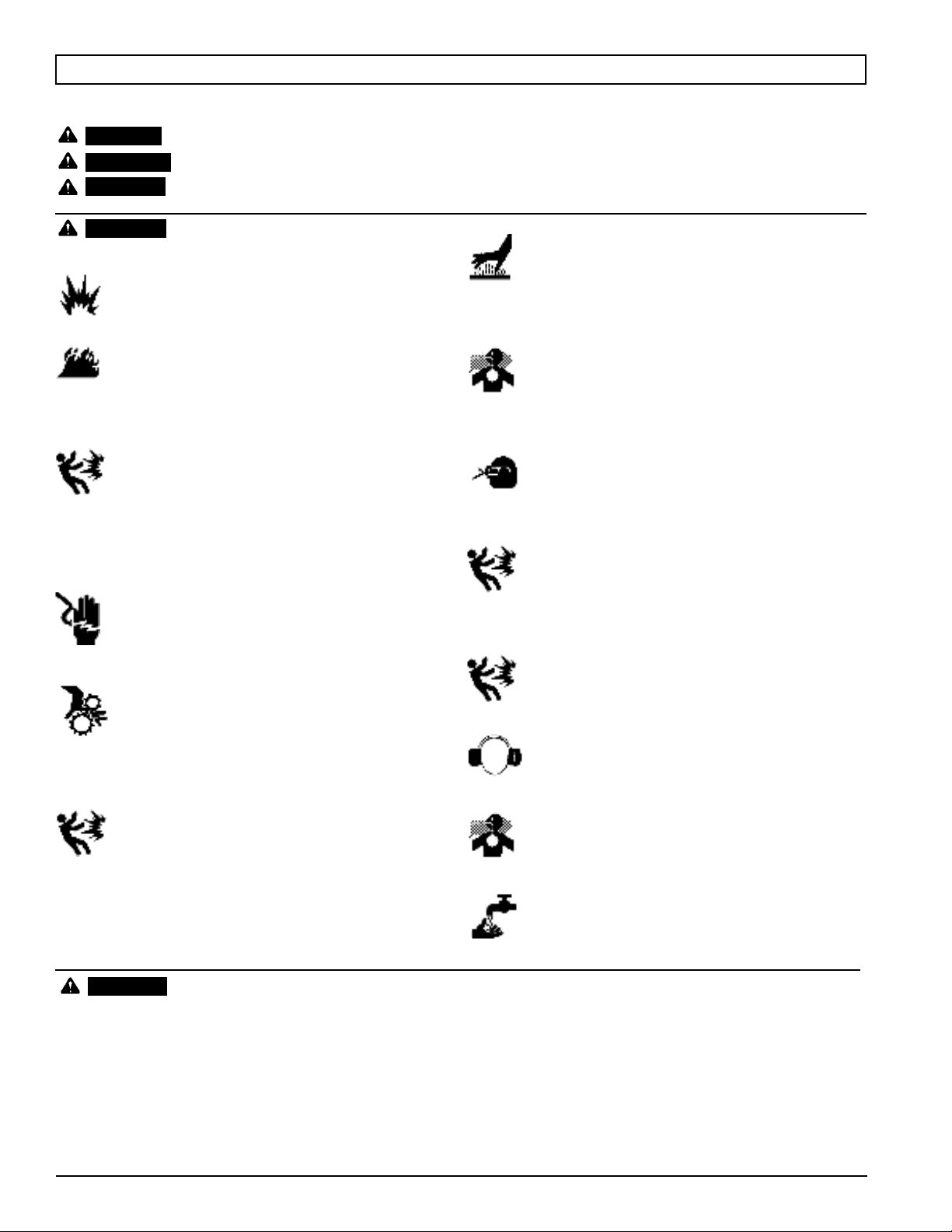
WARNING
SAFETY GUIDELINES
The following information relates to protecting YOUR SAFETY and PREVENTING EQUIPMENT PROBLEMS. To help you recognize this
information, we use the following symbols. Please read the manual and pay attention to these sections.
– A POTENTIAL HAZARD THAT WILL CAUSE SERIOUS INJURY OR LOSS OF LIFE.
– A POTENTIAL HAZARD THAT COULD CAUSE SERIOUS INJURY OR LOSS OF LIFE.
– A POTENTIAL HAZARD THAT MAY CAUSE MODERATE INJURY OR DAMAGE TO EQUIPMENT.
WARNING:
DANGER:
CAUTION:
1. Drain the moisture from the tank on a daily basis. A
clean, dry tank will help prevent corrosion.
2. Pull the pressure relief valve ring daily to ensure that
the valve is functioning properly, and to clear the
valve of any possible obstructions.
3. To provide proper ventilation for cooling, the
compressor must be kept a minimum of 12 inches (31
cm) from the nearest wall, in a well–ventilated area.
4. Fasten the compressor down securely if transporting
is necessary. Pressure must be released from the
tank before transporting.
5. Protect the air hose and electric cord from damage
and puncture. Inspect them weekly for weak or worn
spots, and replace if necessary.
6. To reduce the risk of electric shock, do not expose to
rain. Store indoors.
7. Never operate the compressor if the power cord or
plug are damaged. Take the equipment to the nearest
Authorized Service Center , and a specialist technician
will replace it.
CAUTION

200-27056
Oilless air compressors are factory lubricated for life and do not
require any oil.
The basic components of the air compressor are the electric
motor, pump, pressure switch, and tank.
The electric motor (see A) powers the pump. The electric
motor is equipped with an overload protector and an automatic
reset. If the motor becomes overheated, the overload protector
will shut it down to prevent damage to the motor. When the
motor sufficiently cools, it will automatically reset.
The pump (see A) compresses the air and discharges it
into the tank.
The tank (see B) stores the compressed air.
The pressure switch (see C) shuts down the motor when
the air pressure in the tank reaches the kick–out pressure. As
compressed air is used and the pressure level in the tank drops
to the kick–in pressure, the pressure switch restarts the motor
automatically, without warning, and the pump resumes
compressing air.
OVERVIEW
BASIC AIR COMPRESSOR COMPONENTS
A
BC

200-2705 7
1. Unpack the air compressor. Inspect the unit for damage. If
the unit has been damaged in transit, contact the carrier
and complete a damage claim. Do this immediately
because there are time limitations to damage claims.
2. Check the compressor’s serial label to ensure that you
have received the model ordered, and that it has the
required pressure rating for its intended use.
3. Locate the compressor according to the following
guidelines:
a. Position the compressor near a grounded electrical
outlet (see GROUNDING INSTRUCTIONS, page 9).
Avoid using an extension cord; use a longer hose
instead.
b. The compressor must be at least 12 inches (31 cm)
from any wall or obstruction, in a clean, well-ventilated
area, to ensure sufficient air flow and cooling.
c. In cold climates, store portable compressors in a
heated building when not in use. This will reduce
problems with motor starting and freezing of water
condensation.
d. Remove the compressor from the carton and place it
on the floor or a hard, level surface.
4. Connect an air hose to the compressor hose outlet (A).
ASSEMBLY
ASSEMBLING THE COMPRESSOR
A

200-27058
ON/OFF Switch (see A)
This switch turns on the compressor. It is operated
manually, but when in the ON position, it allows the compressor
to start up or shut down automatically, without warning, upon
air demand. ALWAYS set this switch to OFF when the
compressor is not being used, and before unplugging the
compressor.
Pressure Relief Valve (see B)
If the pressure switch does not shut down the motor when
pressure reaches the preset level, this valve will pop open
automatically to prevent over pressurization. To operate
manually, pull the ring on the valve to relieve air pressure in the
tank.
Tank Pressure Gauge (see C)
This gauge measures the pressure level of the air stored in
the tank. It is not adjustable by the operator, and does not
indicate line pressure.
Air Pressure Regulator (see D)
This air pressure regulator enables you to adjust line
pressure to the tool you are using.
Never exceed the maximum working
pressure of the tool.
Turn the knob clockwise to increase pressure, and
counterclockwise to decrease pressure.
Regulated pressure gauge (see E)
This gauge measures the regulated outlet pressure.
Air line outlet (see F)
Connect an air hose to this outlet.
WARNING:
COMPRESSOR CONTROLS
COMPRESSOR CONTROLS
E
A
F
C
B
D

200-2705 9
Refer to the air compressor’s serial label for the unit’s
voltage and amperage requirements.
NOTE: Avoid use of extension cords.
For optimum performance, plug the compressor power
cord directly into a grounded wall socket. Do not use an
extension cord unless absolutely necessary. Instead, use a
longer air hose to reach the area where the air is needed.
If use of an extension cord cannot be avoided, the cord
should be no longer than 50 feet and be a minimum wire size of
12 gauge (AWG). Do not use a 16 or 14 gauge extension cord.
Use only a 3-wire extension cord that has a 3-blade
grounding plug, and a 3-slot receptacle that will accept the plug
on the product. Make sure your extension cord is in good
condition. An undersized cord will cause a drop in line voltage,
resulting in loss of power and overheating. The smaller the
gauge number, the heavier the cord.
This product should be grounded. In the event of an
electrical short circuit, grounding reduces the risk of electric
shock by providing an escape wire for the electric current.
This product is equipped with a cord having a grounding
wire with an appropriate grounding plug. The plug must be
plugged into an outlet that is properly installed and grounded in
accordance with all local codes and ordinance.
Improper installation of the grounding
plug can result in a risk of electric shock. If repair or
replacement of the cord or plug is necessary, do not
connect the grounding wire to either flat blade
terminal. The wire insulation having an outer surface
that is green with or without yellow stripes is the
grounding wire.
This product is for use on a nominal 115 volt circuit. A cord
with a grounding plug, as shown here, shall be used.
Make sure that the product is connected to an outlet
having the same configuration as the plug (see Figure 1). No
adapter should be used with this product.
Check with a licensed electrician if the grounding instructions
are not completely understood, or if in doubt as to whether the
product is properly grounded. Do not modify the plug provided;
if it will not fit the outlet, have the proper outlet installed by a
licensed electrician.
Grounded Outlet Box
Grounded Outlet
Plug Grounding Pin
DANGER
Figure 1
115 VOLTS
15 AMP
ELECTRICAL POWER REQUIREMENTS
ELECTRICAL WIRING
EXTENSION CORDS
GROUNDING INSTRUCTIONS

200-2705 11
1. Turn the ON/OFF switch to the OFF position (see A).
2. Close the tank drain valve (see D). Turn in the clockwise
direction.
3. Plug in the power cord.
High temperatures are generated
by the electric motor and the pump. To prevent burns
or other injuries, DO NOT touch the compressor while
it is running. Allow it to cool before handling or
servicing. Keep children away from the compressor
at all times.
4. Turn the ON/OFF switch to the ON position (see C).
When adjusting from a higher to a
lower pressure, turn the knob counterclockwise past
the desired setting, then turn clockwise to reach the
desired pressure. Do not exceed operating pressure of
the tool or accessory being used.
5. If a pressure regulator is present on your compressor,
adjust it to the working pressure of the tool.
1. Turn the On/OFF switch to the OFF position (see A).
2. Unplug the power cord.
3. Reduce pressure in the tank through the outlet hose. You
can also pull the relief valve ring (see E) and keep it open
to relieve pressure in the tank.
Escaping air and moisture can
propel debris that may cause eye injury. Wear safety
goggles when opening drain valve.
4. Tip the compressor (if necessary for your model) so
the drain valve is at the bottom of the tank. Then open
the drain valve to allow moisture to drain from the
tank.
WARNING:
WARNING:
CAUTION:
OPERATING INSTRUCTIONS
DAILY STARTUP
SHUTDOWN
B
OPEN
D
CLOSE
E

200-2705 13
To avoid personal injury, always shut off and
unplug the compressor and relieve all air pressure from
the system before performing any service on the air
compressor.
Regular maintenance will ensure trouble free operation.
Your electric powered air compressor represents high quality
engineering and construction; however, even high quality
machinery requires periodic maintenance. The items listed
below should be inspected on a regular basis.
Condensation will accumulate in the
tank. To prevent corrosion of the tank from the inside,
this moisture must be drained at the end of every
workday. Be sure to wear protective eyewear. Relieve
the air pressure in the system and open the drain valve
on the bottom of the tank and tilt tank to drain.
NOTE: In cold climates, drain the tank after each use to
reduce problems with freezing of water
condensation.
WARNING:
WARNING:
MAINTENANCE
MAINTENANCE
DRAINING THE TANK
B
OPEN
D
CLOSE

200-270514
PARTS LIST
040-0418 (U2C) Pump Breakdown
ITEM # 61
ITEM # 60
ITEM # 59

200-2705 15
PARTS LIST
Item Part No Qty Description
1 Order item #59 1 Air Filter, Cap
2 Order item #59 1 Air Filter, Element
3 Order item #59 1 Air Filter, Base
4 040-0418 1 Motor/Pump Asm
5 145-0585 1 Tube, Relief
6 N/A 2 Nut, Comp, 1/4"
7 N/A 2 Ferrule, 1/4"
9 ** 1 Power Cord
10 N/A 1 Strain Relief
11 136-0098 1 Safety Valve
12 034-0224 1 Pressure Switch
13 N/A 1 Nipple, 1/4" mnpt x 25mm
14 N/A 1 Nipple, 1/4" mnpt x 35mm
15 019-0264 1 Regulator
16 036-0084 1 Quick Connect, Steel
17 ** 1 Tank Asm
18 N/A 8 Nut, m8 x 1.25
19 N/A 8 Washer, Lock, m8
20 N/A 12 Washer, Flat, m8
21 094-0183 4 Isolator
22 N/A 4 Bolt, m8 x 1.25 x 25mm
23 072-0018 1 Drain valve
24 N/A 2 Ferrule, 3/8"
25 N/A 2 Nut, Comp, 3/8"
26 145-0586 1 Tube, Outlet
27 031-0091 1 Check Valve, 90 degree, Right
28 N/A 4 Screw, m8 x 15mm
29 ** 1 Handle Grip, Rubber
30 032-0109 2 Gauge, 1.5"
31 N/A 4 Screw, m6 x 1 x 30mm
32 N/A 4 Washer, Lock, m6
33 042-0128 1 Head
34 Order item #60 1 Gasket, Cylinder Head
35 Order item #60 1 Valve Plate assembly
36 Order item #60 2 Reed Valve
37 Order item #60 1 Gasket, Valve Plate
38 Order item #60 1 Valve Plate
39 Order item #60 1 Gasket, Cylinder
40 Order item #61 1 Cylinder
41 ** 1 Motor Shroud
42 ** 1 Eccentric
43 Order item #61 1 Screw, m6 x 1 x 16mm
44 Order item #61 1 Piston Cap
45 Order item #61 1 Piston Ring
46 Order item #61 1 Piston
47 027-0049 1 Fan, Crankcase
48 ** 1 Shroud, F1, Black
49 N/A 7 Screw, m4 x 0.7 x 8
50 N/A 1 Screw, m5 x 0.8 x 10
51 Order item #61 2 Washer, Lock, m5
52 Order item #61 1 Screw, m5 x 0.8 x 15
53 ** 1 Bearing
54 N/A 1 Nut, m6 x 1
55 N/A 1 Screw, m6 x 1 x 20mm
56 ** 1 Fan, Motor
57 N/A 1 Snap Ring, 15mm
58 N/A 3 Washer, Flat, m4
59 019-0265 1 Air Filter Kit; incl 1-3
60 043-0219 1 Valve plate assy (includes items 34-39)
61 048-0129 1 Piston/Cylinder assembly (includes items
40, 43-46 and 51-52)
** Items are not available as replacement parts
N/A - These are standard parts available at your local hardware store

200-270516
Pull the relief valve daily to ensure that it is operating
properly and to clear the valve of any possible obstructions.
Check that all connections are tight. A small leak in any of
the hoses, transfer tubes, or pipe connections will substantially
reduce the performance of your air compressor. If you suspect
a leak, spray a small amount of soapy water around the area of
the suspected leak with a spray bottle. If bubbles appear, repair
or replace the faulty component. Do not overtighten any
connections.
Before storing the compressor for a prolonged period, use
an air blow gun to clean all dust and debris from the
compressor. Disconnect the power cord and coil it up. Pull the
pressure relief valve to release all pressure from the tank. Drain
all moisture from the tank. Cover the entire unit to protect it
from moisture and dust.
Perform the following maintenance at the intervals indicated
below.
Operate the pressure relief valve . . . . . . . . . Daily
Drain tank . . . . . . . . . . . . . . . . . . . . . . . . . . . . Daily
MAINTENANCE
CHECKING THE RELIEF VALVE
TESTING FOR LEAKS
STORAGE
SERVICE INTERVAL

200-2705 17
Note: Troubleshooting problems may have similar causes and solutions.
Close drain valve
Tank drain valve is open
Check fittings with soapy water. Tighten or reseal leaking fittings.
DO NOT OVERTIGHTEN.
Fittings Leak
Clean or replace air filter element.
Restricted air intake
Decrease amount of air used.Prolonged excessive use of air
Check air requirement of accessory. If it is higher than CFM and
pressure supplied by compressor, you need a larger compressor.
Most accessories are rated at 25% of actual CFM while running
continuously.
Compressor not large enough
Check and replace if necessary.Hole in air hose
Immediately replace tank. DO NOT attempt to
repair.
Tank leaks
Replace compressor assembly.Valve leaks
Replace compressor assembly.Leaking or worn piston
Replace compressor assembly.Blown seals
Replace regulator or internal parts.Dirty or damaged regulator
internal parts.
If pressure drops too low, adjust regulator while accessory is used.This is normal
Check air requirement of accessory. If it is higher than CFM and
pressure supplied by compressor, you need a larger compressor.
Most accessories are rated at 25% of actual CFM while running
continuously.
Compressor not large enough
SOLUTIONPOSSIBLE CAUSE
Low pressure or not
enough air
or
Compressor does not
stop
Air leaks from regulator,
or regulator does not
regulate pressure
Regulated pressure
gauge reading drops
when air accessory is
being used
PROBLEM
WARNING:
Replace pressure switch
Tank pressure exceeded normal
operating pressure
Replace pressure switchPressure switch stuck
Motor will start automatically when tank pressure drops below
kick-in pressure of pressure tank.
Tank pressure exceeds preset
pressure switch limit
Let motor cool off and overload switch will automatically reset. This
may take several minutes.
Motor overload protection has
tripped
• Replace blown fuse or resed circuit breaker. Do not use fuse or
circuit breaker with higher rating than specified for your branch
circuit.
Fuse blown or circuit breaker
tripped
• Check for proper fuse; “Fusetron” type T is acceptable.
• Check for low voltage and proper extension cord size.
• Disconnect other applications from circuit. Operate compressor
on a dedicated circuit.
Remove and clean or replace.
Check valve stuck open
Bleed line by moving pressure switch lever to OFF Position before
restarting. If bleeder valve does not open, replace bleeder valve.
Pressure bleeder valve on
pressure switch has not
unloaded head pressure
Check for proper gauge and extension cord length.
Wrong wire gauge in cord or
excessive extension cord length
Contact authorized service center.Loose electrical connections
Contact authorized service center.Possible defective capacitor
Have checked at service center. Do not operate compressor in the
paint spray area
Paint spray on internal motor
parts
Have checked at service center.Possible defective motor
Pressure relief valve
opens
Motor will not run
TROUBLESHOOTING CHART

Replacement parts and service are available from your
nearest authorized Service Center. If the need arises,
contact Product Service as listed at right.
When consulting with a Service Center or Product
Service, refer to the model number and serial number
located on the serial label of the compressor. Proof of
purchase is required for all transactions and a copy of
your sales receipt may be requested.
Record the model number, serial number, and date
purchased in the spaces provided below. Retain your
sales receipt and this manual for future reference.
When needing service, please contact the nearest
authorized Service Center or call:
PRODUCT SERVICE
In U.S.A. or Canada
Toll-Free 1-888-895-4549
Fax 1-507-723-5013
Model No. Serial No. Date Purchased
Product Service
Sanborn Mfg., Division of MAT Industries, LLC.
118 West Rock Street
Springfield, MN 56087
PARTS AND SERVICE
Manufactured in China for
Sanborn Mfg. Division of MAT Industries, LLC., Springfield, MN 56087
© 2008 Sanborn Mfg.
1-888-895-4549
All Rights Reserved
Table of contents
Popular Air Compressor manuals by other brands

EUFAB
EUFAB 21076 manual

Makita
Makita MAC2400 owner's manual

Craftsman
Craftsman 919.174211 owner's manual

Central Pneumatic
Central Pneumatic CENTRAL PNEUMATIC 95499 Assembly and operation instructions

Campbell Hausfeld
Campbell Hausfeld DC130010 Operating instructions and parts manual

Kobalt
Kobalt 200-2614 Operator's manual