manuals.online logo
Brands
  1. Home
  2. •
  3. Brands
  4. •
  5. Pro-Form
  6. •
  7. Treadmill
  8. •
  9. Pro-Form 400 Zlt Treadmill User manual

Pro-Form 400 Zlt Treadmill User manual

Other manuals for 400 Zlt Treadmill

6

This manual suits for next models

1

Other Pro-Form Treadmill manuals

Pro-Form DTL52941 User manual

Pro-Form

Pro-Form DTL52941 User manual

Pro-Form 400 Zlt Treadmill System manual

Pro-Form

Pro-Form 400 Zlt Treadmill System manual

Pro-Form 425 User manual

Pro-Form

Pro-Form 425 User manual

Pro-Form 831.29633.0 User manual

Pro-Form

Pro-Form 831.29633.0 User manual

Pro-Form CROSSWALK si User manual

Pro-Form

Pro-Form CROSSWALK si User manual

Pro-Form 560 Crosstrainer User manual

Pro-Form

Pro-Form 560 Crosstrainer User manual

Pro-Form PCTL53691 User manual

Pro-Form

Pro-Form PCTL53691 User manual

Pro-Form PCTL95235.0 User manual

Pro-Form

Pro-Form PCTL95235.0 User manual

Pro-Form CROSS WALK PLUS User manual

Pro-Form

Pro-Form CROSS WALK PLUS User manual

Pro-Form CROSSWALK ADVANCED 525s User manual

Pro-Form

Pro-Form CROSSWALK ADVANCED 525s User manual

Pro-Form CROSSWALK FIT 415 User manual

Pro-Form

Pro-Form CROSSWALK FIT 415 User manual

Pro-Form LX 670 PFTL512040 User manual

Pro-Form

Pro-Form LX 670 PFTL512040 User manual

Pro-Form 3.6 Treadmill User manual

Pro-Form

Pro-Form 3.6 Treadmill User manual

Pro-Form XP crosswalk 580 User manual

Pro-Form

Pro-Form XP crosswalk 580 User manual

Pro-Form 500 Cx Treadmill

Pro-Form

Pro-Form 500 Cx Treadmill

Pro-Form 520 Trainer User manual

Pro-Form

Pro-Form 520 Trainer User manual

Pro-Form 785 TL User manual

Pro-Form

Pro-Form 785 TL User manual

Pro-Form 831.297460 User manual

Pro-Form

Pro-Form 831.297460 User manual

Pro-Form 585 Perspective Treadmill

Pro-Form

Pro-Form 585 Perspective Treadmill

Pro-Form PFTL39115.3 User manual

Pro-Form

Pro-Form PFTL39115.3 User manual

Pro-Form 760 Air Treadmill Reference guide

Pro-Form

Pro-Form 760 Air Treadmill Reference guide

Pro-Form 790tr Treadmill User manual

Pro-Form

Pro-Form 790tr Treadmill User manual

Pro-Form 824 Exp User manual

Pro-Form

Pro-Form 824 Exp User manual

Pro-Form 831.295062 User manual

Pro-Form

Pro-Form 831.295062 User manual

Popular Treadmill manuals by other brands

Motus M990T Service manual

Motus

Motus M990T Service manual

NordicTrack APEX4100i NTTL18906 user manual

NordicTrack

NordicTrack APEX4100i NTTL18906 user manual

CAPITAL SPORTS Pacemaker Touch manual

CAPITAL SPORTS

CAPITAL SPORTS Pacemaker Touch manual

Insportline Hill Pro user manual

Insportline

Insportline Hill Pro user manual

Expondo Gymrex GR-MG31 user manual

Expondo

Expondo Gymrex GR-MG31 user manual

HEALTH ONE Walk Ro user manual

HEALTH ONE

HEALTH ONE Walk Ro user manual

NordicTrack T7.5 S user manual

NordicTrack

NordicTrack T7.5 S user manual

Gold's Gym ADVANTAGE GGTL12920 user manual

Gold's Gym

Gold's Gym ADVANTAGE GGTL12920 user manual

Merax MS282992 manual

Merax

Merax MS282992 manual

FitLogic freewill d225 owner's manual

FitLogic

FitLogic freewill d225 owner's manual

HOP-SPORT ESTIMA HS-3200LB instruction manual

HOP-SPORT

HOP-SPORT ESTIMA HS-3200LB instruction manual

Stamia InMotion II owner's manual

Stamia

Stamia InMotion II owner's manual

Smooth Fitness EVO 3i user manual

Smooth Fitness

Smooth Fitness EVO 3i user manual

NordicTrack NETL81810.0 user manual

NordicTrack

NordicTrack NETL81810.0 user manual

Schwinn 830/Journey 8.0 Assembly manual / owner's manual

Schwinn

Schwinn 830/Journey 8.0 Assembly manual / owner's manual

Keys Fitness HealthTrainer HT-740T owner's manual

Keys Fitness

Keys Fitness HealthTrainer HT-740T owner's manual

Spirit XT8 Service manual

Spirit

Spirit XT8 Service manual

NordicTrack T 14.0 Treadmill Manuel de l'utilisateur

NordicTrack

NordicTrack T 14.0 Treadmill Manuel de l'utilisateur

manuals.online logo
manuals.online logoBrands
  • About & Mission
  • Contact us
  • Privacy Policy
  • Terms and Conditions

Copyright 2025 Manuals.Online. All Rights Reserved.

Model No. PETL49910.0
Serial No.
Write the serial number in the space
above for future reference.
CAUTION
Read all precautions and instruc-
tions in this manual before using
this equipment. Save this manual
for future reference.
Serial Number
Decal
USER'S MANUAL
QUESTIONS?
If you have questions, or if there are
missing parts, please contact us:
UK
Call: 08457 089 009
From Ireland: 053 92 36102
Website: www.iconsupport.eu
E-mail: [email protected]
Write:
ICON ealth & Fitness, Ltd.
c/o I Group PLC, Express Way
Whitwood, West Yorkshire
WF10 5QJ
UK
AUSTRALIA
Call: 1-800-237-173
E-mail:
[email protected]
www.iconeurope.com
TABLE OF CONTENTS
WARNINGDECALPLACEMENT..............................................................2
IMPORTANTPRECAUTIONS ................................................................3
BEFOREYOUBEGIN ......................................................................5
ASSEMBLY...............................................................................6
OPERATIONANDAD USTMENT ............................................................12
HOWTOFOLDANDMOVETHETREADMILL ..................................................18
TROUBLESHOOTING .....................................................................19
EXERCISEGUIDELINES ...................................................................22
PARTLIST ..............................................................................23
EXPLODEDDRAWING ....................................................................24
ORDERINGREPLACEMENTPARTS ..................................................BackCover
RECYCLINGINFORMATION.........................................................BackCover
2
PROFORM is a registered trademark of ICON IP, Inc.
WARNING DECAL PLACEMENT
This drawing shows the locations of the warning
decals. If a decal is missing or illegible, call
the telephone number on the front cover of
this manual and request a free replacement
decal. Apply the decal in the location shown.
Note: The decals may not be shown at actual
size.
1. Before beginning any exercise program, con-
sult your physician. This is especially impor-
tant for persons over age 35 or persons with
pre-existing health problems.
2. It is the responsibility of the owner to ensure
that all users of this treadmill are adequately
informed of all warnings and precautions.
3. Use the treadmill only as described.
4. Keep the treadmill indoors, away from mois-
ture and dust. Do not put the treadmill in a
garage or covered patio, or near water.
5. Place the treadmill on a level surface, with at
least 8 ft. (2.4 m) of clearance behind it and 2
ft. (0.6 m) on each side. Do not place the
treadmill on any surface that blocks air open-
ings. To protect the floor or carpet from dam-
age, place a mat under the treadmill.
6. Do not operate the treadmill where aerosol
products are used or where oxygen is being
administered.
7. Keep children under age 12 and pets away
from the treadmill at all times.
8. The treadmill should be used only by persons
weighing 265 lbs. (120 kg) or less.
9. Never allow more than one person on the
treadmill at a time.
10. Wear appropriate exercise clothes when
using the treadmill. Do not wear loose clothes
that could become caught in the treadmill.
Athletic support clothes are recommended
for both men and women. Always wear ath-
letic shoes. Never use the treadmill with bare
feet, wearing only stockings, or in sandals.
11. When connecting the power cord (see page
12), plug the power cord into an earthed cir-
cuit. No other appliance should be on the
same circuit. When replacing the fuse in the
power cord adapter, insert an ASTA-approved
BS1362, 13-amp fuse into the fuse carrier.
12. If an extension cord is needed, use only a 3-
conductor, 14-gauge (1 mm2) cord that is no
longer than 5 ft. (1.5 m).
13. Keep the power cord away from heated sur-
faces.
14. Never move the walking belt while the power
is turned off. Do not operate the treadmill if
the power cord or plug is damaged, or if the
treadmill is not working properly. (See TROU-
BLES OOTING on page 19 if the treadmill is
not working properly.)
15. Read, understand, and test the emergency
stop procedure before using the treadmill (see
OW TO TURN ON T E POWER on page 14).
16. Never start the treadmill while you are stand-
ing on the walking belt. Always hold the
handrails while using the treadmill.
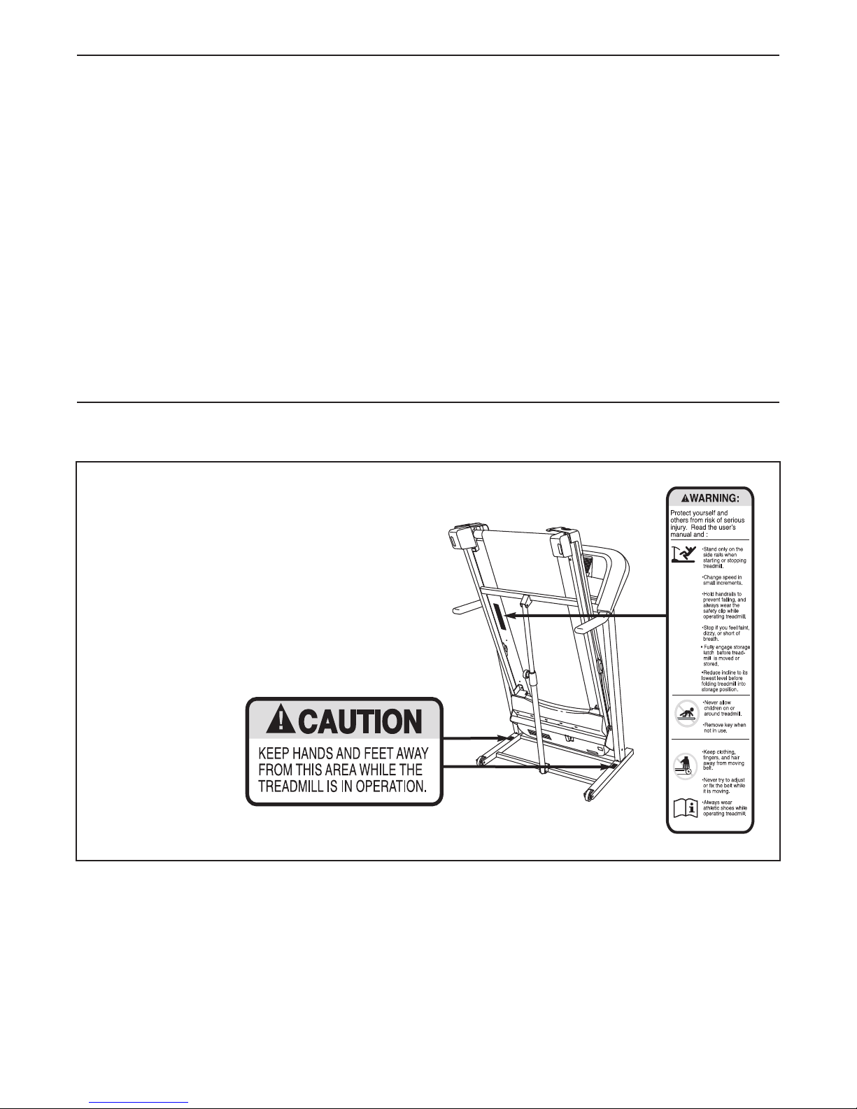
17. The treadmill is capable of high speeds.
Adjust the speed in small increments to avoid
sudden jumps in speed.
18. The pulse sensor is not a medical device.
Various factors, including the user's move-
ment, may affect the accuracy of heart rate
readings. The pulse sensor is intended only
as an exercise aid in determining heart rate
trends in general.
WARNING: To reduce the risk of serious injury, read all important precautions and in-
structions in this manual and all warnings on your treadmill before using your treadmill. ICON as-
sumes no responsibility for personal injury or property damage sustained by or through the use of
this product.
IMPORTANT PRECAUTIONS
3
4
19. Never leave the treadmill unattended while it
is running. Always remove the key, unplug
the power cord, and press the power switch
into the off position when the treadmill is not
in use. (See the drawing on page 5 for the lo-
cation of the power switch.)
20. Do not attempt to raise, lower, or move the
treadmill until it is properly assembled. (See
ASSEMBLY on page 6, and OW TO FOLD
AND MOVE T E TREADMILL on page 18.)
You must be able to safely lift 45 lbs. (20 kg)
to raise, lower, or move the treadmill.
21. When folding or moving the treadmill, make
sure that the storage latch is holding the
frame securely in the storage position.
22. Inspect and properly tighten all parts of the
treadmill regularly.
23. Never insert any object into any opening on
the treadmill.
24. DANGER: Always unplug the power
cord immediately after use, before cleaning
the treadmill, and before performing the
maintenance and adjustment procedures de-
scribed in this manual. Never remove the
motor hood unless instructed to do so by an
authorized service representative. Servicing
other than the procedures in this manual
should be performed by an authorized ser-
vice representative only.
25. This treadmill is intended for in-home use
only. Do not use this treadmill in a commer-
cial, rental, or institutional setting.
26. Over exercising may result in serious injury
or death. If you feel faint or if you experience
pain while exercising, stop immediately and
cool down.
SAVE T ESE INSTRUCTIONS
5
Thank you for selecting the new PROFORM®400 ZLT
treadmill. The 400 ZLT treadmill offers a selection of
features designed to make your workouts at home
more effective. And when youʼre not exercising, the
unique treadmill can be folded up, requiring less than
half the floor space of other treadmills.
For your benefit, read this manual carefully before
using the treadmill. If you have questions after read-
ing this manual, please see the front cover of this man-
ual. To help us assist you, note the product model
number and serial number before contacting us. The
model number and the location of the serial number
decal are shown on the front cover of this manual.
Before reading further, please review the drawing
below and familiarize yourself with the labeled parts.
BEFORE YOU BEGIN
Handrail
Upright
Key/Clip
Power Switch
Walking Belt
Platform Cushion
Foot Rail
Idler Roller
Adjustment Bolts
Console
Fan
Accessory Tray
ASSEMBLY
Assembly requires two persons. Set the treadmill in a cleared area and remove all packing materials. Do not
dispose of the packing materials until assembly is completed. Note: The underside of the treadmill walking
belt is coated with high-performance lubricant. During shipping, some lubricant may be transferred to the top of
the walking belt or the shipping carton. This is normal and does not affect treadmill performance. If there is lubri-
cant on top of the walking belt, simply wipe off the lubricant with a soft cloth and a mild, non-abrasive cleaner.
Assembly requires the included hex keys and your own Phillips screwdriver , rubber
mallet , adjustable wrench , wire cutters , and needlenose pliers .
Use the drawings below to identify the assembly hardware. The number in parentheses below each drawing is
the key number of the part, from the PART LIST near the end of this manual. The number after the parentheses
is the quantity needed for assembly. Note: Some small parts may have been preassembled. To avoid dam-
aging parts, do not use power tools for assembly. Extra hardware may be included.
#8 x 3/4"
Screw (2)–4
3/8" Flat Washer
(33)–2
#8 x 1/2" Ground
Screw (27)–2
Wheel Spacer
(44)–4
1/4" Star
Washer
(21)–2 3/8" Nut (47)–6
3/8" Star
Washer
(39)–4
5/16" Star
Washer
(19)–4
3/8" x 2" Bolt (86)–2
1/4" x 1/2"
Bolt (22)–2
5/16" x 2 1/4" Bolt (20)–4
3/8" x 2 1/4" Bolt (5)–6
3/8" x 2 1/2" Bolt (32)–2
1. Orient the Base (48) as shown.
Identify the Right Upright (36), which has a
square hole near the lower end.
Orient the Right Upright (36) as shown, and
attach it to the Base (48) with two 3/8" x 2 1/4"
Bolts (5) and two 3/8" Star Washers (39); do
not tighten the Bolts yet. 48
Square
Hole
5
5
39
39
36
1
6
7
3. Attach a Wheel (45) to each side of the Base
(48) with a 3/8" x 2 1/4" Bolt (5), two Wheel
Spacers (44), and a 3/8" Nut (47) as shown. Do
not overtighten the Bolts; the Wheels should
turn freely.
48
45
47
44
44
5
45 44
44
5
47
3
2. Orient the Left Upright (31) as shown, and at-
tach it to the Base (48) with two 3/8" x 2 1/4"
Bolts (5) and two 3/8" Star Washers (39); do
not tighten the Bolts yet. Make sure the top
of the Left Upright is angled in the same di-
rection as the top of the Right Upright (36).
48
31
39
39 5
2
4. Raise the Uprights (31, 36) so that the Base (48)
is flat on the floor and positioned as shown.
Cut the tie holding the Upright Wire (28) in a
bundle.
See the far right drawing. Tie the wire tie in the
Right Upright (36) around the end of the Upright
Wire (28). Then, pull the other end of the wire tie
until the Upright Wire is extending from the
upper end of the Right Upright.
Make sure that the end of the Upright Wire
(28) does not fall into the Right Upright (36).
28
Wire Tie
48
28
36
31
Large
Hole
Wire
Tie
36
4
36
8
5. See the left inset drawing. Identify the two
Frame Spacers (34). Open the included grease
packet, and apply grease to both sides of both
Frame Spacers. Then, identify the outer side of
each Frame Spacer.
Hold a Frame Spacer (34) between the Right
Upright (36) and the Lift Frame (59), with the
outer side of the Frame Spacer facing the
Right Upright. Attach the Right Upright to the
Lift Frame with a 3/8" x 2 1/2" Bolt (32), a 3/8"
Flat Washer (33), and a 3/8" Nut (47); do not
tighten the Bolt yet.
5
36
32
32
34
34
33
47
47
59
33
59
Outer
Side
34
36
6. See the left inset drawing. Identify the outer
side of the remaining Frame Spacer (34).
Hold the Frame Spacer (34) between the Left
Upright (31) and the Lift Frame (59), with the
outer side of the Frame Spacer facing the
Left Upright. Attach the Left Upright to the Lift
Frame with a 3/8" x 2 1/2" Bolt (32), a 3/8" Flat
Washer (33), and a 3/8" Nut (47); do not
tighten the Bolt yet.
631
32
32
34
34
33
47
47
59
33
59
Outer
Side
Inner
Side
34 31
Grease
9
7. Route the Upright Wire (28) through one of the
Handrails (18) as shown.
Attach the Handrail (18) to the Right Upright (36)
with two 5/16" x 2 1/4" Bolts (20) and two 5/16"
Star Washers (19). Be careful not to pinch the
Upright Wire (28).
Attach the other Handrail (18) to the Left Upright
(31) with two 5/16" x 2 1/4" Bolts (20) and two
5/16" Star Washers (19). Firmly tighten the
four Bolts.
31
28
20
19
18 20
19
18
7
28
18
9. While another person holds the Console Base
(26) near the right Handrail (18), attach the
ground wire on the Console Base to the right
Handrail with a #8 x 1/2" Ground Screw (27).
Connect the wire harness on the Console Base
(26) to the Upright Wire (28) as shown in the
inset drawing. If the connectors are oriented
correctly, they will slide together easily and
snap into place. If they do not, turn one con-
nector and try again. IF YOU DO NOT CON-
NECT T E CONNECTORS PROPERLY, T E
CONSOLE MAY BECOME DAMAGED W EN
YOU TURN ON T E POWER.
27
26
Ground
Wire
28
Wire
Harness
9
36
8. Insert the included plastic tie through the indi-
cated hole in the right Handrail (18). Make sure
that the Upright Wire (28) is secured to the
inside of the andrail as shown. Then,
tighten the plastic tie.
Remove the wire tie from the Upright Wire (28).
8
Plastic Tie
28
18
Hole
Wire Tie
Wire
Harness
11. Lower the Uprights (31, 36) as shown.
See the inset drawing. Position the Uprights
(31, 36) so that the treadmill Frame (74) is cen-
tered between the Uprights.
Firmly tighten the 3/8" x 2 1/2" Bolts (32) and
then the 3/8" x 2 1/4" Bolts (5) on each side of
the treadmill. Do not overtighten the 3/8" x
2 1/2" Bolts.
36
31, 36
32
74
74
31
View from Above
Side View
11
5
10
22
10. Insert the wires into the Console Base (26) as
you set the Console Base on the Handrails (18).
Be careful not to pinch the wires. Next, thread
two 1/4" x 1/2" Bolts (22) with two 1/4" Star
Washers (21) into the Handrails and the
Console Base; do not tighten the Bolts yet.
Attach the Console Base (26) to the Handrails
(18) with four #8 x 3/4" Screws (2). Then,
tighten the two 1/4" x 1/2" Bolts (22).
See step 8. Remove the plastic tie from the right
Handrail (18). 222
21
21
2
1818
10
26Front View