Pro-Tec Welding PRO-TEC 215 MP User manual

Operating
Manual
protecwelding.com PWOM-215/250MP-001
6-13-2019
PRODUCT
PRO-TEC 215 MP
MULTI-PROCESS
SYSTEM
PART NO.
G1621500
PRODUCT
PRO-TEC 250 MP
MULTI-PROCESS
SYSTEM
PART NO.
G1625000
215
AMPS 3
YEAR
250
AMPS
250MP ONLY
*
*Approvals:CAN/CSA-E60974-1:12,ANSI/IEC60974-1:2008
120 -208240
VAC

Thank you for the purchase of your new PRO-TEC Welding or Cutting
system. We are proud to have you as our customer and will strive to
provide you with the best service and support in the industry.
For product warranty registration or support please visit our website at
www.protecwelding.com.
This Operating Manual has been designed to instruct you on the
correct use and operation of your PRO-TEC Welding or Cutting system.
Your satisfaction with this product and its safe operation is our ultimate
concern. Therefore, please take the time to read the entire manual,
especially the Safety Precautions. They will help you to avoid potential
hazards when working with this product.
Also, check out our website for YouTube video of this product in action!
PRO-TEC is a brand of Welding and Cutting systems from Global Welding
, LLC. We develop optimized solutions for major welding industry sectors
including; Manufacturing, Construction, General Fabrication, Automotive,
Rural and DIY/Hobbyist.
Behind the brand - A team of experienced, great people working together
with passion, enthusiasm and commitment to become a Technology
and Innovation leader in Manual Plasma Cutting and Arc Welding by
partnering with some of the world’s best to develop leading, game
changing innovation for the Cutting and Welding Industry.
“Advanced Welding Solutions”

Read and understand this entire Manual and your employer’s safety practices before
installing, operating, or servicing the equipment. While the information contained in this
Manual represents the Manufacturer’s best judgment, the Manufacturer assumes no lia-
bility for its use
Operating Manual No: PWOM-215/250MP-001 for:
PRO-TEC 215MP MIG/TIG/Stick Arc Welder Package: Part No. G1621500
PRO-TEC 250MP MIG/TIG/Stick Arc Welder Package: Part No. G1625000
Published by: PRO-TEC (Registered Brand of Global Welding LLC)
Box 250
17209 Chesterfield Airport Road, Chesterfield, 63005, Missouri, USA
Website: www.protecwelding.com
Copyright ©2018 PRO-TEC is a Registered Brand of Global Welding LLC.
® All rights reserved.
Reproduction of this Operating Manual, in whole or in part, without written permission of the
publisher is prohibited.
The publisher does not assume and hereby disclaims any liability to any party for any loss or
damage caused by any error or omission in this Operating Manual, whether such error results
from negligence, accident, or any other cause.
Publication Date: January 2019
Record the following information for Warranty purposes
Place of Purchase:
Purchase Date:
Power Source Serial No.:

Table of Contents
SECTION 1 – SAFETY INSTRUCTIONS: Read Before Using Product ....................................... 5
1.1Arc Welding/Cutting Hazard Symbols...............................................................................................................5
1.2Additional Installation, Operation and Maintenance Hazard Symbols...............................................................8
1.3Read Principal Safety Standards.......................................................................................................................8
1.4California Proposition 65 Warnings ..................................................................................................................9
1.5ELECTRIC and MAGNETIC FIELDS (EMF) Recommendations..........................................................................9
SECTION 2 – Instructions De Sécurité: Lire Avant D'utiliser ce Produit .................................. 9
2.1Symboles de danger pour soudage et découpage à l'arc..................................................................................9
2.2Symboles supplémentaires de danger pour l'installation, l'utilisation et l'entretien .......................................12
2.3Lire les principales normes de sécurité...........................................................................................................13
2.4Avertissements de la Proposition 65 de Californie..........................................................................................13
2.5Recommandations relatives aux champs électriques et magnétiques (CEM).................................................13
SECTION 3 – INTRODUCTION...................................................................................14
3.1Description......................................................................................................................................................14
3.2Transportation Methods..................................................................................................................................14
3.3215MP/250MP Duty Cycle at 120 VAC ...........................................................................................................14
3.4215MP Duty Cycle at 208/230/240 VAC .........................................................................................................14
3.5250MP Duty Cycle at 208/230/240 VAC .........................................................................................................15
3.6PRO-TEC 215MP Multi-Process Package..........................................................................................................15
3.7PRO-TEC 250MP Multi-Process Package..........................................................................................................15
3.8Definitions of Terms Used...............................................................................................................................15
3.9Specifications – PRO-TEC 215MP.....................................................................................................................16
3.10Specifications – PRO-TEC 250MP.....................................................................................................................17
SECTION 4 – INSTALLATION.................................................................................... 18
4.1Environment....................................................................................................................................................18
4.2Location ..........................................................................................................................................................18
4.3Explanation of Supply Voltages.......................................................................................................................18
4.4Electrical Input Power Guide...........................................................................................................................18
4.5Extension Cord Recommendations.................................................................................................................18
4.6Connecting 120 VAC Power............................................................................................................................19
4.7Connecting 208 / 230 / 240 VAC Power..........................................................................................................20
4.8MIG SYN Setup for MIG/FCAW (GMAW)........................................................................................................21
4.9Welding Wire Spool Setup: 4” (100mm) ........................................................................................................22
4.10Welding Wire Spool Setup: 8” (200mm) ........................................................................................................22
4.11Drive Roll Types and Sizes..............................................................................................................................22
4.12MIG MAN Setup for MIG/FCAW (GMAW).......................................................................................................23
4.13MIG MAN SPOOL GUN Setup for MIG/FCAW (GMAW) ..................................................................................24
4.14STICK (SMAW) Setup .....................................................................................................................................25
4.15TIG (GTAW) Setup ..........................................................................................................................................26
SECTION 5 – OPERATION .......................................................................................27
5.1Power Source Controls ...................................................................................................................................27
5.2Using Controls ................................................................................................................................................28
5.3Welding Modes and Help Selection ................................................................................................................28
5.4Memory Save/Recall .......................................................................................................................................29
5.5ERROR Displays..............................................................................................................................................29
SECTION 6 – TROUBLESHOOTING and MAINTENANCE..................................................... 30
6.1MIG/FCAW (GMAW) Welding Troubleshooting ..............................................................................................30
6.2STICK Welding Troubleshooting.....................................................................................................................32
6.3TIG Welding Troubleshooting .........................................................................................................................33
6.4Routine Maintenance and Inspection..............................................................................................................34
6.5PRO-TEC 215MP / 250MP Power Source Troubleshooting..............................................................................35
SECTION 7 – PRO-TEC WARRANTY POLICY.................................................................. 37

SAFETY INSTRUCTIONS
© 2018 Global Welding LLC Page 5 Operating Manual No: PWOM-215/250MP-001
SECTION 1 – SAFETY INSTRUCTIONS: Read Before Using Product
DANGER! – Protect yourself and others around you from possible serious injury or death.
1) Read, follow and understand this Operating Manual before installing, operating or servicing this
welding/cutting equipment. 2) Pacemaker wearers keep away until consulting your doctor. 3) Have all
installation, operation, maintenance and repair work performed only by a Suitably Trained and Quali-
fied Tradesperson. 4) Keep children away. 5) Do not lose these instructions.
6) When shipped, ownership is passed to the purchaser upon receipt from the transportation company. Accordingly, claims
for component damage during shipment must be made by the purchaser against the transportation company at the time the
shipment is received.
“NOTE:” Provides information regarding operating recommendations for this welding/cutting equipment.
Welding/cutting equipment and processes can cause serious injury or death, or damage to other equipment or property, if the
operator does not strictly observe all safety instructions and take precautionary actions.
Anyone not extensively trained in welding and cutting practices should not attempt to weld or cut metal.
Safe practices are outlined in American National Standards Institute Z49.1 entitled: SAFETY IN WELDING AND CUTTING. This
publication and other guides of what you should learn before operating this welding/cutting equipment are listed at the end of
these safety instructions.
1.1 Arc Welding/Cutting Hazard Symbols
ELECTRIC SHOCK can kill
Touching live electrical parts can cause
fatal shocks or severe burns. The electrode
and work circuit are electrically live when-
ever the output is on. DO NOT WORK
ALONE! The Input Power Supply circuit
and Power Source internal circuits are also
live when power is on. In semiautomatic
or automatic wire welding, the wire, wire
reel, drive roll housing and all metal parts
touching the welding wire are electrically
live. Incorrectly installed or improperly
grounded welding/cutting equipment is a
hazard.
Do not touch live electrical parts.
Beware of electric shock from wiring.
Do not wrap cables around your body.
Keep all panels and covers securely in place.
Wear dry, hole-free insulating gloves and body protection.
Insulate yourself from work and ground using dry insulating mats
or covers big enough to prevent any physical contact with the
work or ground.
Additional safety precautions are required when any of the follow-
ing electrically hazardous conditions are present:
---In damp locations or while wearing wet clothing;
---On metal structures such as floors, gratings or scaffolds;
---When in cramped positions such as sitting, kneeling or lying;
---When there is a high risk of unavoidable or accidental contact with
the workpiece or ground.
For these conditions, use the following equipment:
1) A semiautomatic DC constant voltage (wire) welder, or
2) A DC manual (stick) welder. In most situations a DC welder is
recommended.
Disconnect Input Power Supply before installing or servicing this
equipment. Lockout/Tagout Input Power Supply according to
OSHA 29 CFR 1910.147.
Properly install and ground this Power Source according to its
Operating Manual and National, State and Local Codes.
Use only well-maintained equipment. Repair or replace damaged
parts at once.
Always verify the Input Power Cord ground − check and be sure
that Input Power Cord ground wire is properly connected to
ground terminal in disconnect box or that Input Power Cord plug
is connected to a properly grounded receptacle outlet.
When making input connections, attach proper grounding conduc-
tor first. DOUBLE - CHECK ALL CONNECTIONS.
Keep all electrical Power Cords dry, free of oil and grease and
protected from hot metal, sparks and sharp metal edges.
Frequently inspect Input Power Cord and ground conductor for
damage or bare wiring. Replace immediately if damaged, bare wir-
ing can kill.
Turn off all equipment when not in use. Disconnect power to
equipment if it will be left unattended or out of service.
Use fully insulated electrode holders. Never dip holder in water to
cool it or lay it down on the ground or the work surface. Do not
touch holders connected to two Power Sources at the same time
or touch other people with the holder or electrode.
Do not use worn, damaged, undersized, repaired or poorly spliced
cables.
Ground the work piece to a good electrical (earth) ground.
Do not touch electrode while in contact with the work (ground)
circuit.
In confined spaces or damp locations, do not use a welder with AC
output unless it is equipped with a voltage reducer. Use equipment
with DC output.
Wear a safety harness to prevent falling if working above floor
level.
Do not touch electrode holders connected to two Power Sources
at the same time as double open-circuit voltage will be present.
Insulate work clamp when not connected to workpiece to prevent
contact with any metal object.
Do not connect more than one electrode or work cable to any
single weld output terminal. Disconnect cable for process not in
use.
Use ground-fault circuit interrupter (GFCI) protection when operat-
ing auxiliary equipment in damp or wet locations.
FLYING METAL or DIRT can injure eyes
Welding, chipping, wire brushin
g
an
d
grinding cause sparks and flying metal.
Welding slag can be thrown off welds as
they cool down.
Wear approved safety glasses (ANSI Z87.1)
with side shields even under your welding
helmet.
Disconnect
SAFETY INSTRUCTIONS
Operating Manual No: PWOM-215/250MP-001 Page 6 © 2018 Global Welding LLC
ARC RAYS can injure eyes and burn skin
Arc rays from the welding process p
r
o
-
duce intense heat and strong ultraviolet
rays that can burn eyes and skin.
Wear a welding helmet fitted with a proper
shade of filter (see ANSI Z49.1 listed in
Safety Standards) to protect your face and
eyes when welding or watching.
Wear approved safety glasses with side shields (ANSI Z87.1).
Use protective screens or barriers to protect others from flash and
glare; warn others not to watch the arc.
Wear protective clothing made from durable, flame-resistant
material (wool and leather) and foot protection.
NOISE can damage hearing
Noise from some processes can damage
hearing.
Use approved ear plugs or ear muffs for
high noise levels environments.
FLYING SPARKS can injure
Flying sparks and hot metal can cause
injury. Chipping and grinding cause flying
metal.
Wear approved face shield and safety gog-
gles.
Wear proper body protection to protect skin
Sparks can cause fire, remove all flammable materials within 35 ft
(10.7 m) of the working zone.
HOT PARTS can burn
Welded parts, cut metal, ground clamp,
electrode stud or torch parts can burn
bare skin when hot.
Don’t touch hot parts with bare skin.
To handle hot parts, use proper tools and/or
wear heavy, insulated welding gloves and
clothing to prevent burns.
EQUIPMENT OVERHEATING
Power Source casing, terminals, cables,
ground clamp, electrode stub or torch parts
can cause injury when overheated.
Allow cooling period before touching
equipment.
Allow cooling period; follow rated duty cycle.
Reduce amperage and/or arc on time before starting to weld
again.
Do not block or filter air vent to Power Source.
FUMES and GASES can be hazardous
FUMES and GASES can be hazardous to
your health. Welding produces fumes and
gases. Breathing these fumes and gases
can be hazardous to your health.
Keep your head out of the fumes. Do not
breathe the fumes.
If inside, ventilate the area and/or use local exhaust at the arc to
remove welding fumes and gases.
If ventilation is poor, use an approved air-supplied respirator.
Read the Safety Data Sheets (SDSs) and the manufacturer’s
instruction for metals, consumables, coatings, cleaners, coolants,
degreasers and fluxes.
Work in a confined space only if it is well ventilated, or while
wearing an air-supplied respirator. Always have an observer
trained in rescue and emergency procedures to monitor the per-
son in a confined space. Shielding gases used for welding can
displace air causing injury or death. Be sure the breathing air is
safe.
Do not weld in locations near degreasing, cleaning, or spraying
operations. The heat and rays of the arc can react with vapors to
form highly toxic and irritating gases.
Do not weld on coated metals, such as galvanized, lead, or cadmi-
um plated steel, unless the coating is removed from the weld area,
the area is well ventilated and if necessary, while wearing an air
supplied respirator. The coatings and any metals containing these
elements can give off toxic fumes if welded.
BUILDUP OF GAS can injure or kill
Shielding GAS used for wire welding ca
n
cause asphyxiation or death in confine
d
places.
Shut off compressed shielding gas supply
when not in use.
Always ventilate confined spaces or use approved air supplied
respirator.
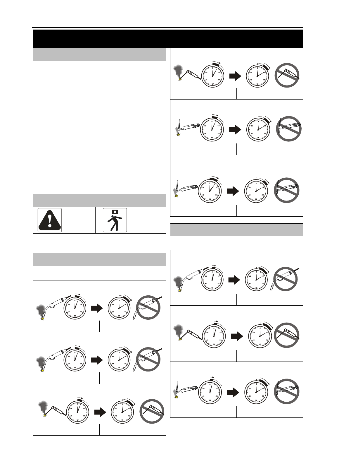
Eye protection filter shade selector numbers for welding or cutting (goggles or helmet)
Welding or Cutting operation Electrode Size
in. (mm)
Arc Amperage
(Amps)
Minimum
Filter Shade Number
Suggested *
Filter Shade Number
Shielded Metal-Arc Welding
(SMAW; STICK)
Less than 3/32 (2.5)
3/32 (2.5) – 5/32 (2.5 – 4.0)
5/32 – 1/4 (4.0 – 6.4)
Less than 60
60 – 160
160 – 250
7
8
10
7
10
12
Gas Tungsten Arc Welding
(GTAW; TIG)
–
Less than 50
50 – 150
150 – 500
8
8
10
10
12
14
Gas metal arc welding (GMAW; MIG)
and
Flux Cored Arc Welding (FCAW; MIG)
–
Less than 60
60 – 160
160 – 250
7
10
10
7
11
12
*As a rule of thumb, start with a shade that is too dark to see the weld or cut zone. Then go to a lighter shade which gives sufficient view of the
weld zone without going below the minimum. This Lens Shade Selector Guide was adapted from ANSI Z49.1, 2012.
SAFETY INSTRUCTIONS
© 2018 Global Welding LLC Page 7 Operating Manual No: PWOM-215/250MP-001
WELDING/CUTTING can cause fire or explosion
Sparks and spatter fly off from the we
l
d
-
ing/cutting arc. The flying sparks and hot
molten metal, weld spatter, hot work
piece and hot equipment can cause fires
and burns. Welding on closed containers,
such as tanks, drums, or pipes, can
cause them to blow up.
Accidental contact of electrode or welding wire t
o
metal
objects can cause sparks, overheating, fire, or explosion.
Check the area is safe before doing any welding.
Protect yourself and others from flying sparks and hot metal.
Do not weld where flying sparks can strike flammable material.
Remove all flammables within 35 ft (10.7 m) of the welding arc. If
this is not possible, tightly cover them with approved covers.
Be aware that welding sparks and hot materials from welding can
easily go through small cracks and openings to adjacent areas.
Watch for fire and keep a fire extinguisher nearby.
Be aware that welding on a ceiling, floor, bulkhead, or partition can
cause fire on the hidden side.
Do not weld on containers that have held combustibles or on
closed containers such as tanks, drums, or pipes unless they are
properly prepared according to AWS F4.1 and AWS A6.0.
Do not weld where the atmosphere contains combustible dust,
gas, or liquid vapors (gasoline for example).
Connect work cable to the work as close to the welding area as
practical to prevent welding amperage from travelling long, possi-
bly unknown paths and causing electric shock and fire hazards.
Do not use welder to thaw frozen pipes.
Remove stick electrode from electrode holder or cut off welding
wire at contact tip when not in use.
Use only correct fuses or circuit breakers. Do not oversize or
bypass them.
Wear body protection made from durable, flame−resistant material
(leather, heavy cotton, wool). Body protection includes oil-free
clothing such as leather gloves, heavy shirt, cuff less trousers,
leather shoes and a cap.
Remove any flammables, such as butane lighter or matches, from
your person before doing any welding.
After completion of work, inspect area to ensure it is free of
sparks, glowing embers and flames.
Follow requirements in OSHA 1910.252 (a) (2) (iv) and NFPA 51B
for hot work and have a fire watcher and extinguisher nearby.
Read and understand the Safety Data Sheets (SDSs) and the
manufacturer’s instructions for adhesives, coatings, cleaners,
consumables, coolants, degreasers, fluxes and metals.
SHIELDING GAS CYLINDERS can explode
Shielding gas cylinders contain gas unde
r
high pressure. If damaged, a cylinder ca
n
explode. Since gas cylinders are normall
y
part of the welding process, be sure t
o
treat them carefully.
Protect compressed gas cylinders from
excessive heat, mechanical shocks and
arcs.
Install and secure cylinder(s) in an upright position by chaining
cylinder(s) to a stationary support or equipment cylinder rack to
prevent falling or tipping.
Keep cylinders away from any welding or other electrical circuits.
Never allow a welding electrode to touch any cylinder.
Use only correct shielding gas cylinders, regulators, hoses and
fittings designed for the specific application; maintain them and
associated parts in good condition.
Turn face away from valve outlet when opening cylinder valve.
Keep protective cap in place over valve except when cylinder is in
use or connected for use.
Read and follow instructions on compressed gas cylinders, asso-
ciated equipment and CGA publication P-1 listed in Safety Stand-
ards.
MOVING PARTS can cause injury
Moving parts, such as fans, drive gears,
rotating wire spools, rotors and belts can
cut fingers and hands and catch loose
clothing.
Keep all doors, panels, covers and guards
closed and securely in place.
Switch OFF Power Source before installing or connecting it
Have only Suitably Trained and Qualified Tradesperson remove
guards or covers for maintenance and troubleshooting as neces-
sary.
To prevent accidental starting during servicing, disconnect Power
Source from power receptacle outlet or disconnect negative bat-
tery cable from battery.
Keep hands, hair, loose clothing and tools away from moving
parts.
When servicing is finished, reinstall panels or guards and close
doors before starting the engine.
WELDING IN RAIN or WATER can cause electric shock
Welding in rain or in water or near wate
r
can increase the risk of electric shock.
Do not weld when in the rain or leave the
Power Source outdoors while it is raining.
Do not weld when standing in or near water.
If water enters Power Source, it must be thoroughly dried and
properly tested before being reused.
SPARKS can cause BATTERY GASES TO EXPLODE;
BATTERY ACID can burn eyes & skin
Batteries contain acid and genera
t
e exp
l
o
-
sive gases.
Always wear a face shield when working on
a battery.
Stop engine before disconnecting or con-
necting battery cables.
Do not allow tools to cause sparks when working on a battery.
Do not use welder to charge batteries or jump start vehicles.
Observe correct polarity (+ and ---) on batteries.
ELECTRIC and MAGNETIC FIELDS (EMF) can affect
Implanted Medical Devices
Consult your doctor and the Implante
d
Medical Device manufacturer before goin
g
near arc welding, spot welding, gouging o
r
plasma arc cutting.
Wearers of Pacemakers and other Implant-
ed Medical Devices should keep away.
SAFETY INSTRUCTIONS
Operating Manual No: PWOM-215/250MP-001 Page 8 © 2018 Global Welding LLC
1.2 Additional Installation, Operation and Maintenance Hazard Symbols
READ OPERATING MANUAL
Read and follow all Power Source labels
and the Operating Manual carefully
before installing, operating, or servicing
the Power Source.
Read the safety information at the begin-
ning of the manual and in each section.
Perform installation, maintenance and
service according to the Operating Manu-
al, industry standards and national, state
and local codes.
IMPROPER INSTALLATION can cause fire
Improper equipment installation can
cause fire.
Do not install or place Power Source on,
over, or near combustible surfaces.
Do not install Power Source near flamma-
bles.
Do not overload building wiring − be sure Input Power Supply
system is properly sized, rated and protected to handle this Power
Source.
Electrostatic discharge can damage electronic components
Touching/handling electronic com
p
o
-
nents or PC Boards without fitting a
ground wrist strap can damage these
parts.
Put on grounded wrist strap before touch-
ing/handling electronic components or PC
Boards.
Use proper static-proof bags and boxes to store, move, or ship
electronic components or PC Boards.
FALLING EQUIPMENT can injure
Use designated lifting device on power
source to lift the power source only,
NOT cart/running gear, gas cylinders, or
any other accessories.
Use lifting equipment of adequate capacity
to lift and support power source.
If using lift forks to move power source, be sure forks are long
enough to extend beyond opposite side of power source.
Keep cables and Power Cords away from moving vehicles when
working from an aerial location.
Follow the guidelines in the
Applications Manual for the Revised
NIOSH Lifting Equation
[DHHS (NOISH) Publication No. 94−110]
when manually lifting heavy parts or Power Source.
ARC WELDING and HIGH FREQUENCY (HF) RADIATION can
cause interference
Arc Welding and HF radiation produces
electromagnetic energy/radio frequen-
cies that can interfere with sensitive
electronic equipment.
Electronics that can be affected are
radios, computers, safety services, tele-
communication equipment and comput-
er-driven equipment such as robots.
Be sure all equipment in the welding area
is electromagnetically compatible.
Have only Suitably Trained and Qualified Tradesperson familiar
with electronic equipment install this equipment.
The user is responsible for having a Suitably Trained and Qualified
Tradesperson promptly correct any interference problem resulting
from the installation.
If notified by the FCC about interference, stop using the equipment
immediately.
Have the installation regularly checked and maintained.
Keep spark gaps at correct setting (if applicable) and use ground-
ing and shielding to minimize the possibility of interference.
To reduce possible interference, keep weld cables as short as
possible, close together and down low, such as on the floor.
Locate welding operation 300 ft from any sensitive electronic
equipment.
Be sure this Power Source is installed and grounded according to
this manual.
If interference still occurs, the user must take extra measures such
as moving the Power Source, using shielded cables, using line
filters, or shielding the work area.
1.3 Read Principal Safety Standards
Safety in Welding, Cutting and Allied Processes, ANSI Standard
Z49.1, is available as a free download from the American Welding
Society at (Website: www.aws.org).
Safe Practices for the Preparation of Containers and Piping for Weld-
ing and Cutting, American Welding Society Standard AWS F4.1, from
Global Engineering Documents (Website: www.global.ihs.com).
Safe Practices for Welding and Cutting Containers that have Held
Combustibles, American Welding Society Standard AWS A6.0, from
Global Engineering Documents (Website: www.global.ihs.com).
National Electrical Code, NFPA Standard 70, from National Fire Pro-
tection Association, Quincy, MA 02269 (Website: www.nfpa.org).
Safe Handling of Compressed Gases in Cylinders, CGA Pamphlet P-1,
from Compressed Gas Association, 14501 George Carter Way, Suite
103, Chantilly, VA 20151 (website: www.cganet. com).
Safety in Welding, Cutting and Allied Processes, CSA Standard
W117.2, from Canadian Standards Association, Standards Sales,
5060 Spectrum Way, Suite 100, Mississauga, Ontario, Canada L4W
5NS (Website: www.csagroup.org).
Safe Practice for Occupational and Educational Eye And Face Protec-
tion, ANSI Standard Z87.1, from American National Standards Insti-
tute, 25 West 43rd Street, New York, NY 10036 (Website:
www.ansi.org). Standard for Fire Prevention During Welding, Cutting
and Other Hot Work, NFPA Standard 51B, from National Fire Protec-
tion Association, Quincy, MA 02269 (Website: www.nfpa.org).
OSHA, Occupational Safety and Health Standards for General Indus-
try,
Title 29, Code of Federal Regulations (CFR), Part 1910, Subpart Q and
Part 1926, Subpart J, from U.S. Government Printing Office, Superin-
tendent of Documents, (Website: www.osha.gov).
Applications Manual for the Revised NIOSH Lifting Equation, The
National Institute for Occupational Safety and Health (NIOSH), 1600
Clifton Rd, Atlanta, GA 30329-4027 (Website: www.cdc.gov/NIOSH).
HF

SAFETY INSTRUCTIONS
© 2018 Global Welding LLC Page 9 Operating Manual No: PWOM-215/250MP-001
1.4 California Proposition 65 Warnings
This Product contain chemicals, including lead, or otherwise produce chemicals known to the State of California to
cause cancer, birth defects and other reproductive harm. Wash hands after handling. (California Health & Safety Code
25249.5 et seq.)
Welding and cutting equipment produce fumes or gases which contain chemicals known to the State of California to
cause birth defects and, in some cases, cancer. Wear an approved air-supplied respirator for welding and cutting. (Cali-
fornia Health & Safety Code Section 25249.5 et seq.)
1.5 ELECTRIC and MAGNETIC FIELDS (EMF) Recommendations
Consult your doctor and
t
he Implanted Medical Device ma
n
u
-
facturer before going near arc welding, spot welding, goug-
ing, or plasma arc cutting.
EMFs are produced around welding cables / accessories
during the welding operation and can interfere with some
medical implants such as pacemakers. All Welding Operators
should use the following procedures in order to minimize
exposure to EMF when welding.
Keep electrode / ground cables away from your body.
Keep electrode / ground cables together by twisting or taping
them together.
Do not place your body in between the electrode and ground
cables.
Do not coil or drape cable around your body.
Keep Power source and accessories as far away from your body
as possible.
Do not weld whilst carrying the Power source or accessories.
Connect the ground clamp to the workpiece as close as possible
to the weld zone.
SECTION 2 – Instructions De Sécurité: Lire Avant D'utiliser ce Produit
DANGER! - Protégez-vous et les autres autour de vous contre les blessures graves ou mortelles.
1) Lire, suivre et comprendre ce manuel d'utilisation avant d'installer, d'utiliser ou d'entretenir cet
équipement de soudage et de découpage. 2) Les porteurs de stimulateurs cardiaques devraient consul-
ter leur médecin avant d’utiliser cet équipement. 3) Les travaux d’installation, de fonctionnement,
d’entretien et de réparation devraient être effectués que par des personnes formées et qualifiées. 4)
Tenir les enfants à l’écart. 5) Ne perdez pas ces instructions. 6) Lorsqu’expédié, la possession du pro-
duit passe de la société de transport à l'acheteur dès réception.
En conséquence, les réclamations pour composants endommagés pendant le transport doivent être effectuées contre la
société de transport au moment de la réception de la commande.
"NOTE:" Fournit des informations concernant les recommandations de fonctionnement de cet équipement de soudage et de
découpage.
L'équipement et les procédés de soudage et de découpage peuvent causer des blessures graves ou mortelles, ou endommager
d'autres équipements ou biens, si l'opérateur n'observe pas strictement toutes les consignes de sécurité et prend des précau-
tions. Toute personne qui n'est pas formée aux méthodes de soudage et de découpage ne doit pas tenter de souder ou de cou-
per du métal. Les pratiques sûres sont décrites dans la norme nationale américaine (ANSI) Z49.1 intitulée: SÉCURITÉ EN SOU-
DAGE ET EN DÉCOUPAGE. Cette publication et d'autres guides sur ce que vous devez apprendre avant d'utiliser cet équipement
de soudage et de découpage sont répertoriés à la fin de ces consignes de sécurité.
2.1 Symboles de danger pour soudage et découpage à l'arc
LECHOC ÉLECTRIQUE peut tuer
Toucher les éléments électriques sous tensions
peut tuer ou causer des brûlures graves.
L’électrode et le circuit de travail sont électri-
quement sous tension chaque fois que la sortie
est activée. NE TRAVAILLEZ PAS SEUL! Le
circuit d’alimentation d'entrée et les circuits
internes de la source d'alimentation sont égale-
ment sous tension lorsque l'alimentation est
activée. En soudage au fil semi-automatique ou
automatique, le fil, la bobine de fil, le rouleau
d'entraînement et toutes les pièces métalliques
qui touchent le fil à soudage sont sous tension.
Un équipement de soudage/découpage mal
installé ou inadéquatement mise à la terre est un
danger.
Ne touchez pas les pièces électriques sous
tension.
Faites attention aux chocs électriques causés
par le câblage.
N’enroulez pas les câbles autour de votre corps.
Gardez tous les panneaux et les couvercles en place.
Portez des gants isolants, secs et sans trous et une protection
pour le corps.
Isolez-vous du travail et du sol en utilisant des tapis isolants et
secs, ou des couvertures suffisamment grandes pour éviter tout
contact physique avec le travail ou le sol.
Des précautions de sécurité supplémentaires sont requises lors-
que l'une ou l'autre des conditions dangereuses suivantes sont
présentes:
- Dans des endroits humides ou portant des vêtements mouillés;
- Sur des structures métalliques telles que des planchers, des grilles
ou des échafaudages;
- Dans des positions confinées telles qu’assises, agenouillées ou
allongées;
- Lorsqu'il existe un risque élevé de contact inévitable ou accidentel
avec le travail ou le sol.
Pour ces conditions, utilisez les équipements suivants:
1) Un soudeur au fil semi-automatique à tension continue DC, ou
2) Une soudeuse à tige manuelle CC. Dans la plupart des cas, un
soudeur à courant continu (CC) est recommandé.
Disconnect
SAFETY INSTRUCTIONS
Operating Manual No: PWOM-215/250MP-001 Page 10 © 2018 Global Welding LLC
Débranchez l'alimentation électrique d'entrée avant d'installer ou
d'entretenir cet équipement. Étiquetez et verrouillez l’alimentation
électrique d'entrée selon OSHA 29 CFR 1910.147.
Installez et mettez à la terre correctement cette source d'alimenta-
tion selon son mode d'emploi et les codes nationaux, régionaux et
locaux.
Utilisez uniquement des équipements bien entretenus. Réparez ou
remplacez les pièces endommagées immédiatement.
Vérifiez toujours la mise à la terre du câble d'alimentation d'entrée
- vérifiez et assurez-vous que le fil de mise à la terre du câble
d'alimentation d'entrée est connecté correctement à la borne de
terre dans le disjoncteur ou que la prise électrique du câble d'ali-
mentation d'entrée est connectée à une sortie de prise de courant
correctement connectée à la terre.
Lorsque vous effectuez des connexions d'entrée, attachez en
première correctement le conducteur de terre. VÉRIFIER TOUTES
LES CONNEXIONS.
Gardez tous les câbles d'alimentation électrique secs, sans aucune
trace d'huile ou de graisse, et protégés des métaux chauds,
d’étincelles et de bords métalliques tranchants.
Inspectez fréquemment le câble d'alimentation d'entrée et le
conducteur de terre pour dommages ou câblage à nu. Remplacez
immédiatement s’ils sont endommagés, le câblage à nu peut tuer.
Fermez tous les appareils lorsqu'ils ne sont pas en service. Dé-
branchez les appareils s’ils seront laissés sans surveillance ou
hors service.
Utilisez des supports d'électrodes complètement isolés. Ne jamais
tremper le support dans l'eau pour le refroidir ou le déposer sur le
sol ou la surface de travail. Ne touchez pas simultanément les
supports connectés à deux sources d'alimentation ou toucher
d'autres personnes avec le support ou l'électrode.
N'utilisez pas de câbles usés, endommagés, sous-dimensionnés,
réparés ou mal épissés.
Mettre la pièce à travailler sur une bonne mise électrique à la terre.
Ne pas toucher l'électrode lorsqu’elle est en contact avec la mise à
la terre.
Dans les espaces confinés ou les endroits humides, ne pas utiliser
de soudeur avec sortie CA, à moins qu'il ne soit équipé d'un ré-
ducteur de tension. Utilisez un équipement avec sortie CC.
Portez un harnais de sécurité pour éviter de tomber si vous travail-
lez au-dessus du niveau du sol.
Ne touchez pas les supports d'électrodes connectés simultané-
ment à deux sources d'alimentation car la tension de circuit ouvert
sera doublée.
Isoler la pince de travail lorsqu'elle n'est pas reliée à la pièce à
travailler pour éviter tout contact avec un objet métallique.
Ne relier pas plus qu'une électrode ou un câble de travail à une
seule borne de sortie de soudage. Débranchez le câble quand il
n’est pas utilisé.
Utilisez un disjoncteur de fuite de terre (GFCI) lorsque vous utilisez
des appareils auxiliaires dans des endroits humides ou mouillés.
PROJECTIONS DE MÉTAL ou PARTICULES peuvent blesser
les yeux
Le soudage, l'écaillage, le brossage des fils et
le broyage provoquent les étincelles et les
projections de métal.
Les scories de soudage peuvent être éjec-
tées des soudures lorsqu'elles refroidissent.
Portez des lunettes protectrices homologuées avec écrans laté-
raux, même sous votre casque de soudage.
LES RAYONS D’ARC peuvent causer des blessures aux
yeux et brûler la peau
Les rayons d'arc du procédé de soudage
produisent une chaleur intense et des rayons
ultraviolets puissants qui peuvent brûler les
yeux et la peau.
Portez des lunettes protectrices homolo-
guées avec de préférence des écrans laté-
raux.
Portez un casque de soudage muni d'une teinte de filtre appro-
priée (voir ANSI Z49.1 figurant dans les Normes de Sécurité) pour
protéger votre visage et vos yeux lors du soudage ou d'une obser-
vation.
Utilisez des écrans ou barrières de protection pour protéger les
autres contre les éclats aveuglants et les éclairs; Avertir les autres
de ne pas regarder l'arc.
Portez des vêtements de protection fait de matériaux résistants
aux flammes (laine et cuir) et une protection pour les pieds.
LE BRUIT peut endommager l'ouïe
Le bruit de certains procédés peut endomma-
ger l'ouïe.
Utilisez des boules Quiès ou des cache-
oreilles homologuées pour des environne-
ments à niveaux sonores élevés.
LES ÉTINCELLES peuvent blesser
Les étincelles et le métal chaud peuvent bles-
ser. L'écaillage et le broyage peuvent projeter
des morceaux de métal.
Portez un masque protecteur homologué ou
des lunettes de protection.
Portez une protection du corps adéquate pour protéger la peau.
Les étincelles peuvent provoquer un incendie; retirer tous les
matériaux inflammables à moins de 35 pieds (10.7 m) de la zone
de travail.
LES PIÈCES CHAUDES peuvent brûler
Les pièces soudées, le métal coupé, la pince
de terre, la tige d'électrode ou les pièces du
chalumeau peuvent brûler la peau nue lors-
qu'ils sont chauds.
Ne touchez pas les pièces chaudes à la peau
nue.
Pour manipuler les pièces chaudes, utilisez des outils appropriés
et / ou portez des gants de soudage lourds et isolés et des vête-
ments pour prévenir les brûlures.
SURCHAUFFE DE L’ÉQUIPEMENT
Le boîtier de la source d'alimentation, les
bornes, les câbles, la pince de terre, la tige
d’électrode ou les pièces du chalumeau peu-
vent blesser quand surchauffés.
Respecter la période de refroidissement
avant de toucher l'équipement.
Respecter la période de refroidissement; suivre le cycle de service
noté.
Réduisez l’ampérage et / ou l'arc avant de recommencer à souder.
Ne pas bloquer ni filtrer la bouche d’aération de la source d'ali-
mentation.

SAFETY INSTRUCTIONS
© 2018 Global Welding LLC Page 11 Operating Manual No: PWOM-215/250MP-001
LES ÉMANATIONS ET LES GAZ peuvent être dangereux
Les émanations et les gaz peuvent être dange-
reux pour votre santé. Le soudage produit des
émanations et des gaz. Respirer ces émana-
tions et ces gaz peuvent être dangereux pour
votre santé.
Gardez votre tête à l’écart des émanations.
Ne pas les respirer.
Si la ventilation est mauvaise, utilisez un appareil respiratoire à
adduction d’air approuvé.
Lisez les fiches signalétiques (SDS) et les instructions du fabricant
pour les métaux, les consommables, les revêtements, les produits
de nettoyage, les liquides de refroidissement, les dégraissants, et
les flux.
Travaillez dans un espace clos seulement s'il est bien ventilé ou en
utilisant un appareil respiratoire à adduction d’air. Il faut toujours
avoir un observateur formé dans les procédures de secours et
d'urgence pour surveiller la personne dans un espace clos. Les
gaz de protection utilisés pour le soudage peuvent déplacer l'air,
pouvant provoquer des blessures ou la mort. Assurez-vous que
l'air respirable est sûr.
À l'intérieur, ventilez la zone et / ou utilisez l'aspiration locale au
niveau de l'arc pour enlever les émanations et les gaz de soudage.
Ne pas souder dans des endroits près d’opérations de dégraissa-
ge, de nettoyage ou de pulvérisation. La chaleur et les rayons de
l'arc peuvent réagir avec les vapeurs pour former des gaz haute-
ment toxiques et irritants.
Ne pas souder sur des métaux revêtus, tels que l'acier galvanisé,
plaqué au plomb ou plaqué au cadmium, à moins que le revête-
ment soit retiré de la zone de soudure, que la zone soit bien venti-
lée et si nécessaire, en portant un appareil respiratoire à adduction
d’air. Les revêtements et tous les métaux contenant ces éléments
peuvent dégager des émanations toxiques s’ils sont soudés.
LES ACCUMULATIONS DE GAZ peuvent blesser ou tuer
Le GAZ de protection utilisé pour le soudage au
fil peut asphyxier ou tuer dans les espaces
clos.
Fermer l’alimentation du gaz comprimé
lorsqu’elle n’est pas utilisée.
Veillez toujours bien aérer les espaces clos ou servez-vous d’un
appareil respiratoire àadduction d’air homologué.
Numéros du sélecteur de la teinte du filtre de protection des yeux pour le soudage ou le découpage (lunettes
ou casque)
Opération de soudage ou découpage Taille de l'électrode
po. (mm)
Courant de
soudage (A)
Le numéro de teinte de filtre
minimum
Numéro de teinte *
de filtre suggéré
Soudage à l’arc métallique blindé
(SMAW; STICK)
Moins que 3/32 (2.5)
3/32 (2.5) – 5/32 (2.5 – 4.0)
5/32 – 1/4 (4.0 – 6.4)
Moins que 60
60 – 160
160 – 250
7
8
10
7
10
12
Soudage à l'arc au tungstène gazeux
(GTAW; TIG)
–
Moins que 50
50 – 150
150 – 500
8
8
10
10
12
14
Soudage à l'arc gaz-métal (GMAW;
MIG) et soudage à l'arc avec fil fourré
(FCAW; MIG)
–
Moins que 60
60 – 160
160 – 250
7
10
10
7
11
12
*En règle générale, commencez par une teinte du filtre de protection trop sombre pour voir la zone de soudage ou de découpage. Ensuite, passez à une teinte plus
claire qui donne une vue suffisante de la zone de soudage ou de découpage sans être inférieure au minimum. Ce guide de sélection de lentille a été adapté d’ANSI
Z49.1, 2012.
LE SOUDAGE / DÉCOUPAGE peut provoquer un incendie
ou une explosion
Les étincelles et les éclaboussures giclent de
l'arc de soudage/découpage. Les étincelles et
le métal en fusion, les éclaboussures de métal,
les pièces de travail et les équipements chauds
peuvent provoquer des incendies et des brûlu-
res. Le soudage sur des conteneurs fermés,
tels que des réservoirs, des bidons ou des
tuyaux, peut les faire exploser.
Le contact accidentel d'électrode ou de fil de soudage sur des objets
métalliques peut causer des étincelles, une surchauffe, un incendie
ou une explosion. Vérifiez que la zone de travail est sûre avant de
procéder à des travaux de soudage.
Protégez-vous et les autres contre les étincelles et le métal chaud.
Ne soudez pas là où les étincelles peuvent frapper des matériaux
inflammables.
Enlevez tous les matériaux inflammables à moins de 10 pieds (10,7
m) de l'arc de soudage. Si cela n'est pas possible, recouvrez-les
avec des couvertures approuvées.
Soyez conscient que les étincelles de soudage et les matériaux
chauds provenant du soudage peuvent facilement passer à travers
des petites fissures et des ouvertures dans les pièces adjacentes.
Surveillez pour un feu éventuel et gardez un extincteur à proximité.
Soyez conscient que le soudage sur un plafond, un plancher, une
cloison ou une partition peut provoquer un incendie sur le côté
caché.
Ne soudez pas sur des conteneurs contenant des combustibles ou
des récipients fermés tels que des réservoirs, des bidons ou des
tuyaux, à moins qu'ils ne soient correctement préparés selon AWS
F4.1 et AWS A6.0.
Ne soudez pas quand l'atmosphère contient des poussières com-
bustibles, des gaz ou des vapeurs (de l’essence par exemple).
Raccordez le câble de travail au travail aussi près que possible de la
zone de soudage, pour empêcher le courant de sillonner une lon-
gue distance, et peut-être un parcours inconnu qui pourrait causer
des chocs électriques et des risques d'incendie.
N’utilisez pas la soudeuse pour dégeler les tuyaux congelés.
Enlevez l'électrode enrobée du support ou coupez le fil de soudage
à la pointe de contact lorsqu'elle n'est pas utilisée.
Utilisez uniquement des fusibles ou des disjoncteurs corrects. Ne
les surdimensionné ou contournez pas.
Portez une protection du corps fait d’un matériau durable et résis-
tant aux flammes (cuir, coton lourd, laine). La protection du corps
comprend des vêtements sans huile tels que des gants en cuir, une
chemise lourde, des pantalons sans ourlets, des chaussures hautes
et une casquette.
Retirez tous les matériaux inflammables de votre personne, tels
qu’un briquet au butane ou des allumettes, avant de souder.
Une fois les travaux achevés, inspectez la zone pour vous assurer
qu’il ne reste pas d'étincelles, de braises et de flammes.
Suivez les exigences de la norme OSHA 1910.252 (a) (2) (iv) et
NFPA 51B pour les travaux à chaud et ayez un piquet d’incendie et
un extincteur à proximité.
Lire et comprendre les fiches signalétiques (SDS) et les instruc-
tions du fabricant pour les adhésifs, les revêtements, les produits
de nettoyage, les consommables, les liquides de refroidissement,
les dégraissants, les flux et les métaux.

SAFETY INSTRUCTIONS
Operating Manual No: PWOM-215/250MP-001 Page 12 © 2018 Global Welding LLC
LES CYLINDRES DE GAZ DE PROTECTION peuvent explo-
ser
Les cylindres de gaz de protection contiennent
du gaz sous haute pression. S’il est endommagé,
un cylindre peut exploser. Étant donné que les
cylindres de gaz font partis du procédé de sou-
dage, assurez-vous de les manipuler avec pré-
caution.
Protégez les cylindres de gaz comprimés contre la chaleur exces-
sive, les chocs mécaniques et les arcs.
Installez et sécurisez le(s) cylindre(s) en position verticale en
attachant le(s) cylindre(s) à un support stationnaire ou à un cadre
pour cylindre pour éviter qu’il tombe(nt) ou ne bascule(nt).
Gardez les cylindres à l'écart de tout soudage ou circuit électrique.
Ne permettez jamais qu’une électrode de soudage puisse toucher
un cylindre.
Utilisez seulement des cylindres de gaz de protection, des régula-
teurs, des tuyaux et des raccords conçus pour l'application spéci-
fique; maintenez-les et les pièces associées en bon état.
Tournez le visage hors de la portée de la sortie de la vanne lorsque
vous ouvrez la vanne du cylindre.
Gardez le capuchon de protection en place sur la vanne, sauf si le
cylindre est utilisé ou prêt à être utilisé.
Lisez et suivez les instructions sur les cylindres de gaz compri-
més, les équipements associés et la publication de la CGA énumé-
rées dans les normes de sécurité.
LES PIÈCES MOBILES peuvent blesser
Les pièces mobiles, telles que les ventilateurs,
les engrenages d'entraînement, les bobines de fil
tournantes, les rotors et les ceintures, peuvent
couper les doigts et les mains et accrocher les
vêtements amples.
Gardez toutes les portes, les panneaux, les couvercles et les
protecteurs de machines bien en place.
Fermez la source d'alimentation avant de l'installer ou de la bran-
cher.
N'utilisez que des personnes qualifiées pour enlever les protec-
teurs de machines ou les couvercles, pour l’entretien et la résolu-
tion de problèmes.
Gardez les mains, les cheveux, les vêtements amples et les outils à
l'écart des pièces mobiles.
Pour prévenir le démarrage accidentel pendant l'entretien, débran-
chez la source d'alimentation de la prise de courant ou débranchez
le câble à pôle négatif de la batterie.
Lorsque l'entretien est terminé, réinstallez les panneaux ou les
protecteurs de machines et fermez les portes avant de démarrer le
moteur.
LES ÉTINCELLES peuvent faire EXPLOSER LES GAZ de
BATTERIE; L'ACIDE DE BATTERIE peut brûler les yeux et la
peau
Les batteries contiennent de l'acide et génèrent
des gaz explosifs.
Portez toujours un masque protecteur lorsque
vous travaillez sur une batterie.
Arrêtez le moteur avant de débrancher ou de
brancher les câbles de la batterie.
Ne laissez pas les outils créer des étincelles lorsque vous travaillez
sur une batterie.
Ne vous servez pas du soudeur pour recharger des batteries ou
démarrer des véhicules.
Observez la polarité correcte (+ et -) sur les batteries.
SOUDERSOUS LA PLUIE ou DANS L'EAU peut donner un
choc électrique
Souder sous la pluie ou dans l'eau ou près d
e
l'eau peut augmenter le risque de choc électrique.
Ne soudez pas sous la pluie, et ne laisse pas
la source d'alimentation à l'extérieur quand il
pleut.
Ne soudez pas debout dans ou près de l'eau.
Si l'eau pénètre dans la source d’alimentation, elle doit être com-
plètement séchée et bien testée avec d’être utilisée à nouveau.
LES CHAMPS ÉLECTRIQUES ET MAGNÉTIQUES (EMF) peu-
vent affecter les appareils médicaux Implantés
Consultez votre médecin et le fabricant de l'ap-
pareil médical implanté avant de vous appro-
cher du soudage à l'arc, au soudage par points,
au gougeage ou découpage à l’arc de plasma.
Les porteurs de stimulateurs cardiaques et
d'autres appareils médicaux implantés de-
vraient se tenir à l'écart.
2.2 Symboles supplémentaires de danger pour l'installation, l'utilisation et l'entretien
LIRE LE MANUEL D’INSTRUCTIONS
Lisez et suivez attentivement toutes les étiquettes
de la source d'alimentation et le manuel
d’instructions avant d'installer, d'utiliser ou
d'entretenir la source d'alimentation.
Lisez les informations de sécurité au début du
manuel et dans chaque section.
Effectuez l'installation, l’entretien et le service
conformément au manuel d’instructions, aux
normes de l'industrie et aux codes nationaux,
régionaux et locaux.
L’INSTALLATION INADÉQUATE peut causer un incendie
L'installation inadéquate de l'équipement peut
causer un incendie.
Ne pas installer ou placer une source d'ali-
mentation sur, au-dessus ou à proximité de
surfaces combustibles.
Ne pas installer de source d'alimentation à
proximité de produits inflammables.
Ne pas surcharger le câblage du bâtiment - assurez-vous que la
source d'alimentation d'entrée est correctement dimensionnée,
évaluée et protégée pour gérer cette source d'alimentation.
LE SOUDAGE À L’ARC ET LA RADIATION À HAUTE FRÉ-
QUENCE (HF) peuvent causer des interférences
Le soudage à l'arc et la radiation à haute fré-
quence produisent de l'énergie électromagnéti-
que et des fréquences de radio qui peuvent
interférer avec des appareils électroniques
sensibles.
Les appareils électroniques qui peuvent être
affectés sont les radios, les ordinateurs, les
services de sécurité, les appareils de télé-
communication et les appareils informatiques
tels que les robots.
Assurez-vous que tous les appareils dans la
zone de soudage sont compatibles au niveau
électromagnétique.
N'ayez que des personnes qualifiées qui connaissent bien ces
appareils électroniques pour les installer.
Vérifiez et faites entretenir l'installation régulièrement.
HF

SAFETY INSTRUCTIONS
© 2018 Global Welding LLC Page 13 Operating Manual No: PWOM-215/250MP-001
L'utilisateur est responsable d'avoir un électricien qualifié pour
corriger rapidement tout problème d'interférence relié à l'installa-
tion.
Si vous êtes avisé par la FCC qu’il y a des interférences, cessez
d'utiliser l'équipement immédiatement.
Gardez les éclateurs bien réglés et utilisez la mise à la terre et le
blindage pour minimiser la possibilité d'interférence.
Pour réduire les interférences possibles, gardez les câbles de
soudage aussi courts et proches que possible, et en bas, de préfé-
rence sur le sol.
Localisez l’opération de soudage à 300pieds de tous appareils
électroniques sensibles.
Assurez-vous que cette source d'alimentation soit installée et mise
à la terre conformément à ce manuel.
Si des interférences se produisent, l'utilisateur doit prendre des
mesures supplémentaires telles que déplacer la source d'alimenta-
tion, utiliser des câbles blindés, utiliser des filtres de ligne ou blin-
der la zone de travail.
La décharge électrostatique peut endommager les compo-
sants électroniques
Toucher / manipuler les composants électroni-
ques ou des cartes de circuit imprimé sans
porter un bracelet de mise à la terre peut en-
dommager ces pièces.
Mettez un bracelet de mise à la terre avant de
toucher / manipuler des composants électro-
niques ou des cartes de circuit imprimé.
Utilisez des sacs et des boîtes antistatiques pour stocker, déplacer
ou expédier des composants électroniques ou des cartes de circuit
imprimé.
LES APPAREILS QUI TOMBENT peuvent blesser
Utilisez le dispositif de levage conçu pour la
source d'alimentation pour soulever uniquement
la source d'alimentation, et non PAS le chariot /
le mécanisme de roulement, les cylindres de gaz
ou tout autre accessoire.
Utilisez un dispositif de levage de capacité
suffisante pour soulever et soutenir la source
d'alimentation.
Si vous utilisez des fourches de levage pour déplacer la source
d'alimentation, assurez-vous que les fourches soient suffisam-
ment longues pour s'étendre au-delà du côté opposé de la source
d'alimentation.
Gardez les câbles et les cordons d'alimentation loin des déplace-
ments de véhicules lorsque vous travaillez en hauteur.
Suivez les directives du Manuel d'application de l'Équation de
levage NIOSH révisée [publication DHHS (NOISH) n ° 94-110] lors
du soulevage manuel de pièces lourdes ou de la source d'alimen-
tation.
2.3 Lire les principales normes de sécurité
Safety in Welding, Cutting and Allied Processes, ANSI Standard Z49.1, is avail-
able as a free download from the American Welding Society at (Website:
www.aws.org).
Safe Practices for the Preparation of Containers and Piping for Welding and
Cutting, American Welding Society Standard AWS F4.1, from Global Engineer-
ing Documents (Website: www.global.ihs.com).
Safe Practices for Welding and Cutting Containers that have Held Combustibles,
American Welding Society Standard AWS A6.0, from Global Engineering Doc-
uments (Website: www.global.ihs.com).
National Electrical Code, NFPA Standard 70, from National Fire Protection
Association, Quincy, MA 02269 (Website: www.nfpa.org).
Safe Handling of Compressed Gases in Cylinders, CGA Pamphlet P-1, from
Compressed Gas Association, 14501 George Carter Way, Suite 103, Chantilly,
VA 20151 (website: www.cganet. com).
Safety in Welding, Cutting and Allied Processes, CSA Standard W117.2, from
Canadian Standards Association, Standards Sales, 5060 Spectrum Way, Suite
100, Mississauga, Ontario, Canada L4W 5NS (Website: www.csagroup.org).
Safe Practice For Occupational And Educational Eye And Face Protection, ANSI
Standard Z87.1, from American National Standards Institute, 25 West 43rd
Street, New York, NY 10036 (Website: www.ansi.org). Standard for Fire Preven-
tion During Welding, Cutting and Other Hot Work, NFPA Standard 51B, from
National Fire Protection Association, Quincy, MA 02269 (Website:
www.nfpa.org).
OSHA, Occupational Safety and Health Standards for General Industry,
Title 29, Code of Federal Regulations (CFR), Part 1910, Subpart Q and Part
1926, Subpart J, from U.S. Government Printing Office, Superintendent of
Documents, (Website: www.osha.gov).
Applications Manual for the Revised NIOSH Lifting Equation, The National
Institute for Occupational Safety and Health (NIOSH), 1600 Clifton Rd, Atlanta,
GA 30329-4027 (Website: www.cdc.gov/NIOSH).
2.4 Avertissements de la Proposition 65 de Californie
Ce produit contient des produits chimiques, y compris le plomb, ou engendre des produits chimiques connus de l'État de
Californie pour causer le cancer, des anomalies congénitales et d'autres problèmes reproductifs. Se laver les mains après
la manipulation. (Code santé et sécurité de la Californie, 25249.5 et suivants).
Les appareils de soudage et de découpage produisent des émanations ou des gaz qui contiennent des produits chimiques
connus de l'État de Californie pour causer des anomalies congénitales et, dans certains cas, le cancer. Portez un appareil
respiratoire à adduction d’air approuvé pour le soudage et le découpage. (Section 25249.5 et suivants du Code de santé et
de sécurité de la Californie).
2.5 Recommandations relatives aux champs électriques et magnétiques (CEM)
Consultez votre médecin et le fabricant de l'appareil médical implan-
té avant de vous approcher du soudage à l'arc, au soudage par
points, au gougeage ou découpage à l’arc de plasma.
Les CEM sont produits autour de câbles et accessoires de soudage
pendant le soudage et peuvent interférer avec certains implants
médicaux tels que les stimulateurs cardiaques. Tous les opérateurs
de soudage devraient utiliser les procédures suivantes afin de mini-
miser l'exposition aux CEM lors du soudage.
Gardez les câbles d'électrode et de mise à la terre ensemble en les
tordant ou en les collant ensemble.
Gardez l’électrode et les câbles de mise à la terre loin de votre
corps.
Ne placez pas votre corps entre l'électrode et les câbles de mise
à la terre.
N’embobinez pas ou ne drapez pas le câble autour du corps.
Gardez la source d'alimentation et les accessoires aussi loin que
possible de votre corps.
Ne soudez pas en portant la source d'alimentation ou les acces-
soires.
Raccordez la pince de terre à la pièce de travail le plus près
possible de la zone de soudage.
INTRODUCTION
Operating Manual No: PWOM-215/250MP-001 Page 14 © 2018 Global Welding LLC
SECTION 3 – INTRODUCTION
3.1 Description
The Multi-Process PRO-TEC 215MP and PRO-TEC 250MP welding
machines features:
---Multiple Input Power, 1 Phase 120 / 208 / 230 / 240 VAC.
---Extremely Portable inverter welding machines with excellent
welding characteristics.
---Self contained MIG (GMAW/FCAW) Wire Welder.
---PRO-TEC MIG Gun or Spool Gun operation.
---Performs MIG (GMAW/FCAW), STICK (SMAW) and LIFT TIG
(GTAW) welding processes.
---A multitude of features are designed into these machines to
satisfy the broad operating needs of the DIY or professional
welder.
---Memory Save/Recall Button enables you to Save or Recall a
total of nine of your favorite weld programs.
---Full color digital LCD displays preview weld parameters then
actual weld parameters when welding.
---Fully compliant to CAN/CSA-E60974-1 & ANSI/IEC 60974-1.
This Operating Manual explains how to safely and correctly set up
these welding machines and provides recommendations on how to
achieve quality from the Power Source. Please read this Operating
Manual thoroughly before operating the PRO-TEC 215MP or PRO-TEC
250MP welding machines.
3.2 Transportation Methods
Disconnect
Power Source
before moving
Falling Power
Source can
cause serious
personal injury
Lift the Power Source only with handle on top of case. Use handcart
or similar device of adequate capacity and secure Power Source
before transporting.
3.3 215MP/250MP Duty Cycle at 120 VAC
The rated duty cycle of the Power Source, is a statement of the time
it may be safely operated at its rated Welding Amperage output.
MIG (GMAW/FCAW) @ 120 VAC
/
15 A Outlet
(35% Duty Cycle at 110 A)
3.5 Minutes Welding
in any 10 Minute Period
6.5 Minutes Non-Welding
in any 10 Minute Period
MIG (GMAW/FCAW) @ 120 VAC/20 A Outlet
(35% Duty Cycle at 140 A)
3.5 Minutes Welding
in any 10 Minute Period
6.5 Minutes Non-Welding
in any 10 Minute Period
STICK (SMAW) @ 120 VAC/15A Outlet
(35% Duty Cycle at 100 A)
3.5 Minutes Welding
in any 10 Minute Period
6.5 Minutes Non-Welding
in any 10 Minute Period
STICK (SMAW) @ 120 VAC/20A Outlet
(50% Duty Cycle at 110 A)
5 Minutes Welding
in any 10 Minute Period
5 Minutes Non-Welding
in any 10 Minute Period
Lift TIG (GTAW) @ 120 VAC/15 A Outlet
(40% Duty Cycle at 140 Amps)
4 Minutes Welding
in any 10 Minute Period
6 Minutes Non-Welding
in any 10 Minute Period
Lift TIG (GTAW) @ 120 VAC/20 A Outlet
(60% Duty Cycle at 140 Amps for 215MP
and 70% Duty Cycle at 140 Amps for 250MP)
6 Minutes Welding
in any 10 Minute Period
4 Minutes Non-Welding
in any 10 Minute Period
3.4 215MP Duty Cycle at 208/230/240 VAC
The rated duty cycle of the Power Source, is a statement of the time
it may be safely operated at its rated Welding Amperage output.
MIG (GMAW/FCAW) @ 208
/
230
/
240 VAC
(25% Duty Cycle at 200 A)
2.5 Minutes Welding
in any 10 Minute Period
7.5 Minutes Non-Welding
in any 10 Minute Period
STICK (SMAW) @ 208
/
230
/
240 VAC
(25% Duty Cycle at 200 A)
2.5 Minutes Welding
in any 10 Minute Period
7.5 Minutes Non-Welding
in any 10 Minute Period
LIFT TIG (GTAW) @ 208
/
230
/
240 VAC
(25% Duty Cycle at 200 A)
2.5 Minutes Welding
in any 10 Minute Period
7.5 Minutes Non-Welding
in any 10 Minute Period

INTRODUCTION
© 2018 Global Welding LLC Page 15 Operating Manual No: PWOM-215/250MP-001
3.5 250MP Duty Cycle at 208/230/240 VAC
The rated duty cycle of the Power Source, is a statement of the time
it may be safely operated at its rated Welding Amperage output.
MIG (GMAW/FCAW) @ 208
/
230
/
240 VAC
(25% Duty Cycle at 250 A)
2.5 Minutes Welding
in any 10 Minute Period
7.5 Minutes Non-Welding
in any 10 Minute Period
STICK (SMAW) @ 208
/
230
/
240 VAC
(25% Duty Cycle at 250 A)
2.5 Minutes Welding
in any 10 Minute Period
7.5 Minutes Non-Welding
in any 10 Minute Period
LIFT TIG (GTAW) @ 208
/
230
/
240 VAC
(25% Duty Cycle at 250 A)
2.5 Minutes Welding
in any 10 Minute Period
7.5 Minutes Non-Welding
in any 10 Minute Period
3.6 PRO-TEC 215MP Multi-Process Package
PRO-TEC 215MP Multi-Process Package,
Part No. G1621500, comes complete with:
Power Source with 250 V NEMA 6-50P Plug, 10 ft 12AWG Cable
Power Adapter 250 V/50 A to 120 V/15 A
1/8 in., E6013 Sample Electrodes, Qty 4
MIG Gun 10 ft 215 A
Electrode Holder & Cable 10 ft
Argon Flow-gauge Regulator
Operating Manual
17 TIG Torch 12.5 ft
TIG Accessory Kit
Ground Clamp & Cable 10 ft
Gas Hose (12.5 ft)
3.7 PRO-TEC 250MP Multi-Process Package
PRO-TEC 250MP Multi-Process Package,
Part No. G1625000, comes complete with:
Power Source with 250 V NEMA 6-50P Plug, 10 ft 12AWG Cable
Power Adapter 250 V/50 A to 120 V/15 A
1/8 in., E6013 Sample Electrodes, Qty 4
MIG Gun 12 ft 250 A
Electrode Holder & Cable 10 ft
Argon Flow-gauge Regulator
Operating Manual
17 TIG Torch 12.5 ft
TIG Accessory Kit
Ground Clamp & Cable 10 ft
Gas Hose (12.5 ft)
3.8 Definitions of Terms Used
MIG SYN: Pre loaded MIG (GMAW/FCAW) welding param-
eters for easy setup of Fe, Ss, Al, FCAW-S,
FCAW-G Welding Wire using a MIG Gun only.
MIG MAN: MIG (GMAW/FCAW) welding parameters are
setup by the Operator for most Welding Wire
with a MIG Gun or Spool Gun.
Memory Button: Save or Recall your weld programs
from a memory chip inside the Power Source.
TIG: Pre loaded DC Lift TIG (GTAW) welding parame-
ters for easy setup based on the selected tung-
sten electrode size.
STICK: Pre loaded DC STICK (SMAW) welding parame-
ters for easy setup the selected STICK electrode
type and size.
Fe: Mild steel MIG welding.
Ss: Stainless steel MIG welding.
Al: Aluminum MIG welding.
FCAW-S: Flux Cored Arc Welding (self shielded).
FCAW-G: Flux Cored Arc Welding (gas shielded).
Arc Force (DIG): Additional amperage during low voltage
(short arc length) conditions while welding.
Downslope: The gradual ramping down of weld amperage
over a period of time.
Inductance: For MIG SYN or MIG MAN modes only. Adjusts
the intensity of the MIG welding arc.
Post Flow Gas: For LIFT TIG mode only. The time Gas flows
after the arc has extinguished to cool the Tung-
sten Electrode and reduce oxidization.
50 Dinse Style: Welding terminal connector.
120 VAC / 15 A Outlet (Nema 5-15R): North American
homes / workshops are wired with 15 Amp,
120-volt circuits with 14-gauge wire and is pro-
tected by a 15 Amp circuit breaker or fuse.
Nema 5-15P: 3 prong power cord plug and rated to 120 V
/ 15 A.
120 VAC / 20 A Outlet (Nema 5-20R): North American
homes / workshops are wired with 20 Amp,
120-volt circuits with 12 or 10-gauge wire and
is protected by a 20 Amp circuit breaker or fuse.
Nema 6-50P: Heavy duty 3 prong power cord plug and
rated to 250 V / 50 A.
Nema 6-50R: Heavy duty 3 prong socket and rated to 250
V / 50 A.
AWG: American Wire Gauge (AWG) is a standard set
of non-ferrous electrical wire conductor sizes.
Duty Cycle: The welding time period (arc on time) as a per-
centage over a 10 minute period.
KVA: Kilovolt-ampere is 1000 volt-amperes where
volt-ampere is the multiplication of volt x am-
pere.
OCV: Nominal Open Circuit Voltage at the welding
terminals.
Delay Fuse: Time Delay Fuse to UL class RK5.
NOTE 1:
PRO-TEC reserves the right to change, improve or revise the
specifications or design of these products without prior notice. Such
updates or changes do not entitle the buyer of equipment previously
sold or shipped to the corresponding changes, updates, improvements
or replacement. The values specified in the table above are nominal
parameters, your products parameters may differ. Individual Power
Source may differ from the above specifications due to in part, but not
exclusively, to any one or more of the following; variations or changes
in manufactured components, installation location / conditions and
local Input Power Supply Grid conditions.
(
Spool Gun
)

INTRODUCTION
Operating Manual No: PWOM-215/250MP-001 Page 16 © 2018 Global Welding LLC
3.9 Specifications – PRO-TEC 215MP
Refer to NOTE 1 on Page 15.
Power Source Part Number G1621599
Weight 39 lb (17.8 kg)
Dimensions H x W x D 16.6 in. x 8.8 in. x 18.5 in.
(421 mm x 223 mm x 469 mm)
CAN/CSA-ANSI/IEC Standards for Safety Arc
Welding Equipment - Part 1: Welding Power
Sources
CAN/CSA-E60974-1:12
ANSI/IEC 60974-1:2008
Memory Locations for Weld Programs 9
Cooling Method Fan Cooled
Environmental
Protection
Class
Welding in rain or
near water can cause
electric shock.
IP23S
[Power Source is designed for indoor and outdoor use]
Output Terminal Type 50 Dinse Style
Input Supply Voltage (Nominal) 120 VAC
15 A Outlet
120 VAC
20 A Outlet
208 VAC 230 VAC 240 VAC
Number of Phases Single Phase Single Phase
Input Supply Voltage Range 104 – 127 VAC 187 – 264 VAC
Power Factor 0.99 0.99
Nominal Input Supply Frequency 50/60 Hz 50/60 Hz
Effective Input Supply Current (l1 eff) MIG
Stick
Lift TIG
Δ 14.4 A
Δ 14.7 A
Δ 15.0 A
Δ 19.8 A
Δ 19.6 A
Δ 18.6 A
13.8 A
15.5 A
10.8 A
12.4 A
14.0 A
9.8 A
11.9 A
13.5 A
9.4 A
^ Min. Recommended Single Phase Generator 5.5 KVA (4.4 KW) 8.6 KVA (6.9 KW)
Fitted Plug, Input Cable Length, Cable Size 240 V NEMA 6-50P Plug, 6.5 ft, 12 AWG
Output Welding Power with MIG 120 VAC
15 A Outlet
120 VAC
20 A Outlet
208 VAC 230 VAC 240 VAC
Welding Amperage Range 10 – 140 A 10 – 215 A
Welding Voltage Range 10 – 26 V
Nominal DC Open Circuit Voltage (OCV) 45 VDC (controlled OCV)
Rated Input Supply Current for MIG Δ 24.4 A Δ 33.4 A 27.5 A 24.9 23.9 A
at Rated Output/Duty Cycle for MIG (GMAW &
FCAW)
110 A @ 19.5 V /
35% Duty Cycle
140 A @ 21 V /
35% Duty Cycle
215 A @ 24.8 V/
25% Duty Cycle
Rated Maximum Input 2.9 KVA 4.0 KVA 5.7 KVA
Wirefeed Speed Range 120 - 980 IPM 120 - 980 IPM
Wire Type
and
Diameter
Aluminum .035 - .040 in. .035 - .040 in.
Mild Steel .023 - .040 in. .023 - .040 in.
Stainless Steel .030 - .040 in. .030 - .040 in.
Flux Cored .035 - .045 in. .035 - .045 in.
Output Welding Power with Stick 120 VAC
15 A Outlet
120 VAC
20 A Outlet
208 VAC 230 VAC 240 VAC
Welding Amperage Range 10 - 110 A 10 – 200 A
Nominal DC Open Circuit Voltage (OCV) 45 VDC (controlled OCV)
Rated Maximum Input Supply Current for Stick Δ 24.9 A Δ 27.8 A 31.1 A 28.1 26.9 A
at Rated Output/Duty Cycle for Stick (SMAW) 100 A @ 24.0 V /
35% Duty Cycle
110 A @ 24.4 V /
50% Duty Cycle
200 A @ 28.0 V /
25% Duty Cycle
Rated Maximum Input 3.0 KVA 3.3 KVA 6.5 KVA
Output Welding Power with Lift TIG 120 VAC
15 A Outlet
120 VAC
20 A Outlet
208 VAC 230 VAC 240 VAC
Welding Amperage Range 10 - 140 A 10 - 200 A
Nominal DC Open Circuit Voltage (OCV) 45 VDC (controlled OCV)
Rated Input Supply Current for TIG Δ 24.0 A Δ 24.0 A 21.7 A 19.6 18.8 A
at Rated Output/Duty Cycle for Lift TIG (GTAW) 140 A @ 15.6V /
40% Duty Cycle
140 A @ 15.6V /
60% Duty Cycle
200 A @ 18 V /
25% Duty Cycle
Rated Maximum Input 2.9 KVA 2.9 KVA 4.5 KVA
Δ The recommended time delay fuse or circuit breaker size is 40 amps for 120 VAC / 20 Amp outlet with an individual branch circuit. An
individual branch circuit capable of carrying 40 amperes and protected by fuses or circuit breaker is recommended for this application. Fuse
size is based on not more than 200% of the rated input amperage of the Power Source. Refer to National Electrical Code Article 630.12.
^ The Minimum Recommended Generator Size is greater than the Rated Maximum Input KVA due to 0.8 Power Factor of Generators and
large variations in performance / specifications of different brands / types of generators. PRO-TEC cannot guarantee Maximum Output Welding
Power on various brands / types of generators.
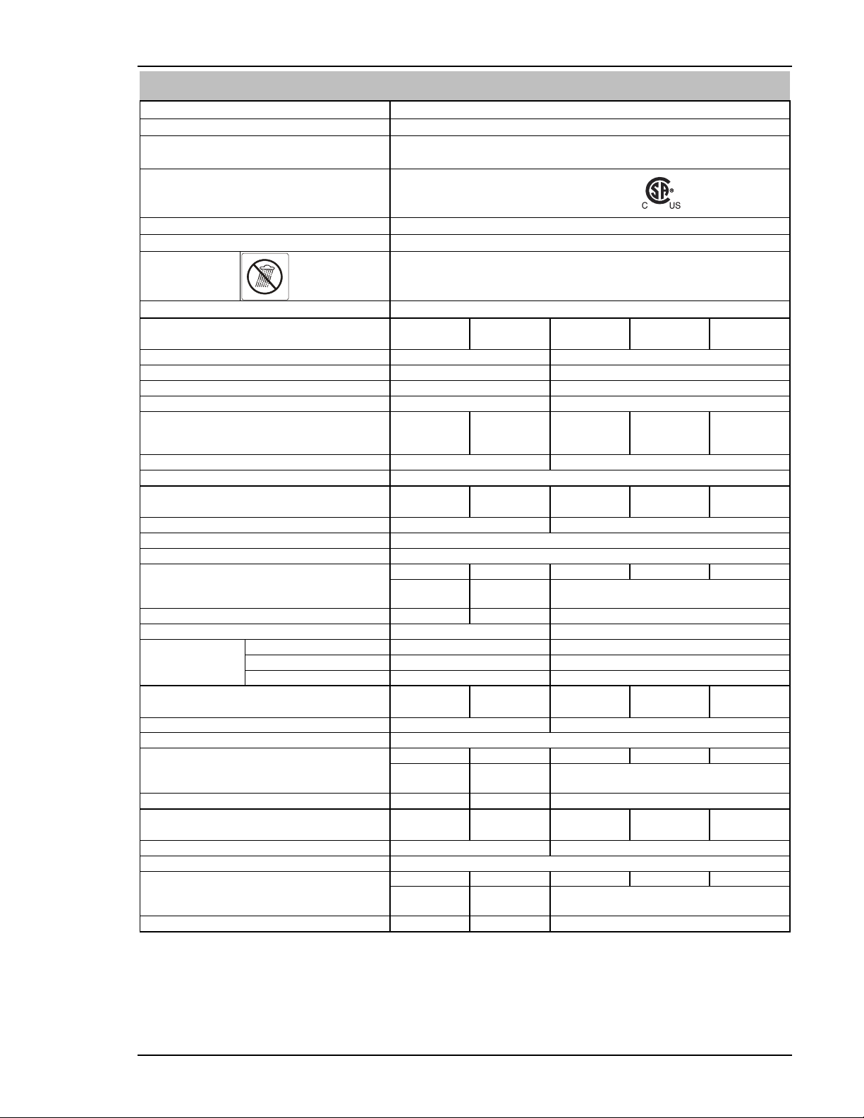
INTRODUCTION
© 2018 Global Welding LLC Page 17 Operating Manual No: PWOM-215/250MP-001
3.10 Specifications – PRO-TEC 250MP
Refer to NOTE 1 on Page 15.
Power Source Part Number G1625099
Weight 48 lb (22 kg)
Dimensions H x W x D 16.6 in. x 8.8 in. x 21.0 in.
(421 mm x 223 mm x 534 mm)
CAN/CSA-ANSI/IEC Standards for Safety Arc
Welding Equipment - Part 1: Welding Power
Sources
CAN/CSA-E60974-1:12
ANSI/IEC 60974-1:2008
Memory Locations for Weld Programs 9
Cooling Method Fan Cooled
Environmental
Protection
Class
Welding in rain or
near water can cause
electric shock.
IP23S
[Power Source is designed for indoor and outdoor use]
Output Terminal Type 50 Dinse Style
Input Supply Voltage (Nominal) 120 VAC
15 A Outlet
120 VAC
20 A Outlet
208 VAC 230 VAC 240 VAC
Number of Phases Single Phase Single Phase
Input Supply Voltage Range 104 – 127 VAC 187 – 264 VAC
Power Factor 0.98 0.98
Nominal Input Supply Frequency 50/60 Hz 50/60 Hz
Effective Input Supply Current (l1 eff) MIG
Stick
Lift TIG
Δ 14.3 A
Δ 14.7 A
Δ 14.9 A
Δ 19.5 A
Δ 19.6 A
Δ 19.7 A
18.8 A
21.6 A
14.5 A
17.0 A
19.5 A
13.1 A
16.3 A
18.7 A
12.6 A
^ Min. Recommended Single Phase Generator 5.5 KVA (4.4 KW) 11.7 KVA (9.4 KW)
Fitted Plug, Input Cable Length, Cable Size 240 V NEMA 6-50P Plug, 6.5 ft, 12 AWG
Output Welding Power with MIG 120 VAC
15 A Outlet
120 VAC
20 A Outlet
208 VAC 230 VAC 240 VAC
Welding Amperage Range 10 – 140 A 10 – 250 A
Welding Voltage Range 10 – 30 V
Nominal DC Open Circuit Voltage (OCV) 45 VDC (controlled OCV)
Maximum Input Supply Current for MIG (l1 max) Δ 24.1 A Δ 33.0 A 37.6 A 34.0 A 32.6 A
at Rated Output/Duty Cycle for MIG
Welding (GMAW & FCAW)
110 A @ 19.5 V /
35% Duty Cycle
140 A @ 21 V /
35% Duty Cycle
250 A @ 26.5 V /
25% Duty Cycle
Rated Maximum Input 2.9 KVA 4.0 KVA 7.8 KAV
Wirefeed Speed Range 120 - 980 IPM 120 - 1180 IPM
Wire Type
and
Diameter
Aluminum .035 - .040 in. .035 - .045 in.
Mild Steel / Stainless Steel .023 - .040 in. .023 - .045 in.
Flux Cored .035 - .045 in. .035 - .045 in.
Output Welding Power with Stick 120 VAC
15 A Outlet
120 VAC
20 A Outlet
208 VAC 230 VAC 240 VAC
Welding Amperage Range 10 - 110 A 10 – 250 A
Nominal DC Open Circuit Voltage (OCV) 45 VDC (controlled OCV)
Maximum Input Supply Current for Stick Δ 24.9 A Δ 27.8 A 43.1 A 39.0 A 37.4 A
at Rated Output/Duty Cycle for Stick
Welding (SMAW)
100 A @ 24.0V /
35% Duty Cycle
110 A @ 24.4V /
50% Duty Cycle
250 A @ 30.0 V/
25% Duty Cycle
Rated Maximum Input 3.0 KVA 3.3 KVA 8.8 KVA
Output Welding Power with Lift TIG 120 VAC
15 A Outlet
120 VAC
20 A Outlet
208 VAC 230 VAC 240 VAC
Welding Amperage Range 10 - 140 A 10 - 250 A
Nominal DC Open Circuit Voltage (OCV) 45 VDC (controlled OCV)
Maximum Input Supply Current for TIG (l1 max) Δ 23.5 A Δ 23.5 A 29.0 A 26.2 A 25.1 A
at Rated Output/Duty Cycle for Lift TIG
Welding (GTAW)
140 A @ 15.6V /
40% Duty Cycle
140 A @ 15.6V /
70% Duty Cycle
250 A @ 20 V /
25% Duty Cycle
Rated Maximum Input 2.8 KVA 2.8 KVA 6.0 KVA
Δ The recommended time delay fuse or circuit breaker size for welding is shown in Table 1 (with Input Supply Voltage = 120 VAC) and an
individual branch circuit is recommended for this application. Fuse/Circuit Breaker size is based on not more than 200% of the rated input
amperage of the Power Source. Refer to National Electrical Code Article 630.12.
^ The Minimum Recommended Generator Size is greater than the Rated Maximum Input KVA due to 0.8 Power Factor of Generators and
large variations in performance / specifications of different brands / types of generators. PRO-TEC cannot guarantee Maximum Output Weld-
ing Power on various brands / types of generators.

INSTALLATION
Operating Manual No: PWOM-215/250MP-001 Page 18 © 2018 Global Welding LLC
SECTION 4 – INSTALLATION
4.1 Environment
This Power Source is designed with an Ingress Pro-
tection (IP) Rating of IP23S and is suitable for:
a) Welding Indoors when the area is adequately ven-
tilated to remove welding fumes away from user.
b) Weld Outdoors ONLY when it is NOT RAINING
.
c) An environment where –
The risk of an electric shock or electrocution by arc
welding is low;
Normal work practices are used; and
It is not possible for a welder or any other workers
to be in contact with the workpiece, in the event of
coming into contact with a “hot” welding circuit.
DANGER – DO NOT weld in rain or in water or
near water or leave the Power Source outdoors
while it is raining.
4.2 Location
Be sure to locate the Power Source according to the
following guidelines:
In areas free from oil, steam, corrosive gases moisture,
standing water and dust.
In areas with ambient temperatures between 32° F to
104° F (0°C to 40° C).
In areas not subjected to abnormal vibration or shock.
In areas not exposed to direct rain or sunlight.
Place at a distance of 12 in. (300mm) or more from
walls or similar that could restrict natural air flow for
cooling.
DANGER – P
RO
-
TEC
advises that these Power
Sources be electrically connected by a Suitably
Trained and Qualified Tradesperson.
4.3 Explanation of Supply Voltages
208 VAC, 220 VAC, 230 VAC and 240 VAC are often used inter-
changeably for commonly available higher powered electrical prod-
ucts. 110 VAC, 115 VAC and 120 VAC are often used interchangea-
bly for commonly available lower powered electrical products.
However, the use of these various voltage terminologies is largely
inaccurate.
110/115 VAC: Are outdated and typically no longer supplied by
utilities. 120 VAC replaces 110/115 VAC.
120 VAC: 120 Volts AC is the common low voltage
supplied by US / Canadian utilities. See Sec-
tion 3.9 or 3.10 regarding usage at this volt-
age.
208 VAC: 208 Volts AC is a specific voltage supplied to
commercial facilities. See Section 3.9 or 3.10
regarding usage at this voltage.
230 VAC: Is outdated and typically no longer supplied by utili-
ties. 240 VAC replaces 230 VAC.
240 VAC: 240 Volts AC is a specific voltage supplied to
commercial facilities. See Section 3.9 or 3.10
regarding usage at this voltage.
4.4 Electrical Input Power Guide
Failure to follow these electrical input power
guide recommendations could create an
electric shock or fire hazard. These recom-
mendations are for a dedicated circuit sized
for the rated output and duty cycle of the
power source.
In dedicated circuit installations, the
National Electrical
Code allows the receptacle outlet or conductor rating to be
less than the rating of the circuit protection device. See NEC
articles 210.21, 630.11 and 630.12.
NOTE 2: Actual input voltage should not exceed ± 10% of
indicated required input voltage.
PRO-TEC 215MP Single Phase Input Power Guide
Single Phase Input
Supply Voltage
208 / 230 /
240 VAC
120 VAC @
20 A
120 VAC @
15 A
Max Input Supply Current: 31.1/28.1/26.9 A 33.4 A 24.9 A
Minimum Recommended
Fuse or Circuit Breaker:
Delay Fuse (UL class RK5)
Normal Fuse (UL class K5)
35/30/30 Amps
40/35/35 Amos
40 Amps
With a 20
amp individu-
al branch
circuit pro-
tected by
time-delay
fuse or circuit
breaker.
30 Amps
With a 20
amp individu-
al branch
circuit pro-
tected by
time-delay
fuse or circuit
breaker.
Minimum Recommended
Grounding Conductor Size 12 AWG
Minimum Recommended
Input Conductor Size 12 AWG
PRO-TEC 250MP Single Phase Input Power Guide
Single Phase Input
Supply Voltage
208 / 230 / 240
VAC
120 VAC /
20A Outlet
120 VAC /
15 A Outlet
Max Input Supply Current: 43.1/39.0/37.4 A 33.0 A 24.9 A
Minimum Recommended
Fuse or Circuit Breaker:
Delay Fuse (UL class RK5)
Normal Fuse (UL class K5)
45/40/40 A
50/45/45 A
40 A
With a 20
amp individu-
al branch
circuit pro-
tected by
time-delay
fuse or circuit
breaker.
30 A
With a 20
amp individu-
al branch
circuit pro-
tected by
time-delay
fuse or circuit
breaker.
Minimum Recommended
Grounding Conductor Size 12 AWG
Minimum Recommended
Input Conductor Size 12 AWG
NOTE 3: These products configures the Power Source to the
operating parameters for 120 / 208 / 230 / 240 VAC.
4.5 Extension Cord Recommendations
DANGER – Never use an extension cord outdoors that is
not marked for outdoors use. Make sure equipment is OFF
before connecting extension cord to outlet. Do not use an
extension cord when wet. Inspect extension cord thor-
oughly before each use. Do not use if damaged. Uncoil
extension cord and do not cover it with any other material.
Input Supply Voltage
Single Phase Input Voltage
208 / 230 / 240 VAC 120 VAC
Recommended Conductor Size 12 AWG 12 AWG
Maximum Extension Cord Length 50 ft. 25 ft.

INSTALLATION
© 2018 Global Welding LLC Page 19 Operating Manual No: PWOM-215/250MP-001
4.6 Connecting 120 VAC Power
Installation must meet all National and Local
Codes. This installation must be electrically con-
nected by a Suitably Trained and Qualified
Tradesperson.
DO NOT TOUCH any live electrical parts or conductors.
Touching live electrical parts can cause fatal
shocks or severe burns. The electrode and
work circuit is electrically live whenever the
output is on.
DO NOT WORK ALONE! The Input Power
Supply circuit and Power Source internal cir-
cuits are also live when power is on.
NOT
E
4
: T
h
es
e
Produc
t
s
configures the Power Source
to the operating parameters for 120 / 208 / 230 / 240
VAC.
Electrical Input Requirements
Operate the Power Source from a single-phase, 50/60
Hz, AC Power Supply available on SITE. The Input
Supply Voltage must match one of the electrical input
voltages shown in this manual.
Refer to Figure 1 and Table 1 for connection, maxi-
mum Input Supply Voltage and Fuse Size.
120 Volts AC Input Supply
Voltage with
Individual Branch Circuit
Delay Fuse or Circuit Breaker
Size
120VAC / 15 A Outlet 30 Amps
120VAC / 20 A Outlet 40 Amps
Table 1
–
120VAC Electrical Fuse or Circuit Breaker Size
NOT
E
5
:
The tim
e
-
delay fuse or circuit breaker of an
individual branch circuit may have nuisance tripping
when welding with this Power Source
due to the am-
perage rating of the time-delay fuse or circuit breaker.
The recommended time delay fuse or circuit breaker
size for welding is shown in Table 1 (with Input Supply
Voltage = 120 VAC) and an individual branch circuit is
recommended for this application. Fuse/Circuit Breaker
size is based on not more than 200% of the rated input
amperage of the Power Source. Refer to National Elec-
trical Code Article 630.12.
Use the
Power Adapter
(2and 3) to connect the Power Source Input Power Cord Plug (1) to the Receptacle Outlet (4).
1Power Source
Input Power
Cord plug (Nema
6-50P)
2Power adapter
receptacle
(Nema 6-50R)
3Power adapter
plug (Nema 5-
15P)
4Customer Sup-
plied Receptacle
Outlet (Nema
5−20R or Nema
5-15R)
Figure 1 – 120 VAC Electrical Input Power Supply Connections
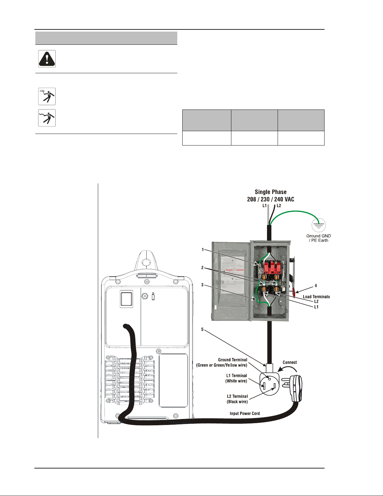
INSTALLATION
Operating Manual No: PWOM-215/250MP-001 Page 20 © 2018 Global Welding LLC
4.7 Connecting 208 / 230 / 240 VAC Power
Installation must meet all National and Local
Codes. This installation must be electrically con-
nected by a Suitably Trained and Qualified Trades-
person.
DO NOT TOUCH any live electrical parts or conductors.
Touching live electrical parts can cause fatal
shocks or severe burns. The electrode and work
circuit is electrically live whenever the output is
on.
DO NOT WORK ALONE! The Input Power Sup-
ply circuit and Power Source internal circuits
are also live when power is on.
NOTE 6: These products configures the Power Source to the
operating parameters for 120 / 208 / 230 / 240 VAC.
Electrical Input Requirements
Operate the Power Source from a single-phase, 50/60 Hz,
AC Power Supply available on SITE. The Input Supply Volt-
age must match one of the electrical input voltages shown in
this manual.
Refer to Figure 2 and Table 2 for connection, maximum
Input Supply Voltage and Fuse Size.
NOTE 7:DO NOT connect an Input Power Cord (WHITE or
BLACK) cable to the ground terminal.
NOTE 8:DO NOT connect an Input Power Cord ground
(GREEN) cable to the Input Primary Supply terminal.
Input Supply
Voltage
PRO-TEC 215MP
Normal Fuse
(UL class K5)
PRO-TEC 250MP
Normal Fuse
(UL class K5)
208 / 230 / 240
VAC
40 / 35 / 35
Amps
50 / 45 / 45
Amps
Table 2
–
208 / 230 / 240 VAC Electrical Fuse Sizes
Use established Lockout/Tagout procedures, refer to OSHA 29 CFR 1910.147, when connecting or disconnecting the Welder’s Input
Power Cord to/from the Input Supply Voltage.
Connect the Power Source Input Power Cord Plug into the Receptacle Outlet (5), Customer Supplied.
1Ground GND / PE
Earth terminal.
2Over-Current Protec-
tion devices
Select type and size of
over-current protec-
tion using Table 2.
3Green or Green/Yellow
Grounding Conductor
- Connect green or
green/yellow ground-
ing conductor to dis-
connect device
grounding terminal
first.
- Connect input con-
ductors L1 and L2 to
disconnect device line
terminals.
4Disconnect device
switch (shown in OFF
position)
5NEMA 6-50R Recep-
tacle (Customer Sup-
plied)
Close and secure door on
the disconnect device.
Connect welding leads to
Power Source.
Remove lockout / Tagout
device and switch to the
ON position.
Figure 2 – 208 / 230 / 240 VAC Electrical Input Power Supply Connections
This manual suits for next models
3
Table of contents
Popular Welding System manuals by other brands

Thermal Dynamics
Thermal Dynamics MERLIN 6000 Service manual

KOLARC
KOLARC TIG 271 Operator's manual

ESAB
ESAB TXH Series instruction manual

ProMeister
ProMeister MIG 200 Translation of original operating instructions

Masterweld
Masterweld Pulse-Expert M-400S Operator's manual

Blueweld
Blueweld Starmig 223 Treo Synergic instruction manual

Matco Tools
Matco Tools MM200 LCD Operator's manual

SincoSald
SincoSald NOVAMIX 541 AC/DC DP instruction manual

Lincoln Electric
Lincoln Electric POWER-ARC 4000 SVM103-A Service manual

MAC TOOLS
MAC TOOLS MW250 owner's manual

Miller
Miller Millermatic Spoolmate 185 Spool Gun owner's manual

Spartus
Spartus EasyTIG 203P DC user manual


