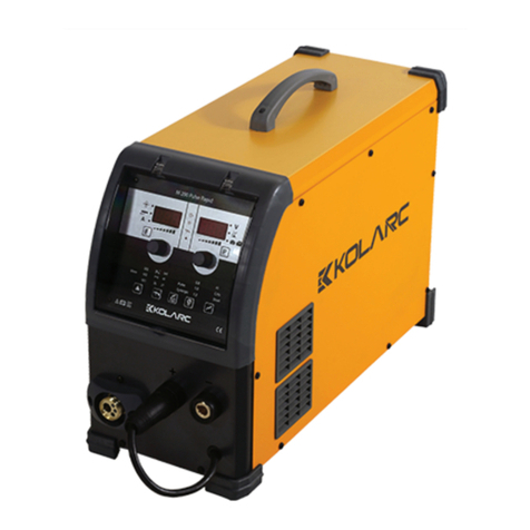
KOLARC TIG 271 User manual

29
KOLARC TIG 271
KOLARC TIG 400
OPERATOR MANUAL

2
Welcome
Thank you and congratulations on choosing KOLARC product. This Owner’s
Manual is designed to help you get the most out of your KOLARC products.
Please take time to read the Safety precautions. They will help you protect
yourself against potential hazards in the workplace. With proper maintenance
this equipment should provide years of reliable service. All our systems
conform to ISO9001:2015 and are independently audited by TCS.
The entire product range carries the CE mark, and is constructed in accordance
with European directives and the product specific standards where they apply.
Further Information
KOLARC is the TURKEY's leading supplier of MMA, MIG, TIG and SAW inverter
welding machines.
For more information about KOLARC’s complete range visit: www.kolarc.com
www.kolarc.com

3
Contents
1.0 SAFETY PRECAUTIONS.......................................4
2.0 PRODUCT DESCRIPTION .....................................7
3.0 TECHNİCAL SPECIFICATIONS ............................7
4.0 DESCRIPTION OFCONTROLS.............................8
4.1 Symbols and Definitions .............................8
4.2 Description of the Machine.........................9
4.3 Device Control ............................................11
5.0 INSTALLATION ....................................................14
Unpacking the Machine......................................14
Location…………................................................14
Input and GroundingConnection .......................14
Output PolarityConnections...............................14
Torch Cooling…… ..............................................14
Incorrect protective gas adjustment!..................15
6.0 OPERATION..........................................................16
6.1 Operation Selecting the JOB........................16
6.2 Operation (2T) ..............................................17
6.3 Operation (4T) ..............................................17
6.4 Operation (S4T)............................................18
Operation Smart Trigger.....................................18
6.5 TIG Operation...............................................19
6.6 MMAWelding................................................19
6.7 Basic TIG WeldingGuide.............................21
7.0 FAULT FINDING ...................................................23
7.1 Repair and Maintenance..............................25
7.2 Error Codes.. ................................................27
8.0 STATEMENT OF WARRANTY ............................28
9.0 EC Declaration of Conformity............................29

4
1.0 SAFETY PRECAUTIONS
ELECTRIC SHOCK can kill.
Touching live electrical parts can cause fatal shocks or severe burns. The electrode and work circuit is
electrically live whenever the output is on. The input power circuit and machine internal circuits are also
live when power is on. In semiautomatic or automatic wire welding, the wire, wire reel, drive roll housing,
and all metal parts touching the welding wire are electrically live. Incorrectly installed or improperly
grounded equipment is a hazard.
Do not touch live electrical parts.
Wear dry, sound insulating gloves and body protection.
Insulate yourself from work and ground using dry insulating mats or covers big enough to prevent any
physical contact with the work ground.
Additional safety precautions are required when any of the following electrically hazardous conditions are
present: in damp locations or while wearing wet clothing; on metal structures such as floors, gratings, or
scaffolds; when in cramped positions such as sitting, kneeling, or lying; or when there is a high risk of
unavoidable or accidental contact with the work piece or ground. For these conditions, use the following
equipment in order presented:
1) a semiautomatic DC constant voltage welder,
2) a DC manual (stick) welder and do not work alone!
Disconnect input power before installing or servicing this equipment. Lockout/tagout input power
according to Safety Standards.
Properly install and ground this equipment according to national and local standards.
Always verify the supply ground - check and ensure that input power cable ground wire is properly
connected to ground terminal in the receptacle outlet.
When making input connections, attach proper grounding conductor first - double-check connections.
Frequently inspect input power cable for damage or bare wiring - replace cable immediately if damaged -
bare wiring can kill.
Turn off all equipment when not in use.
Do not use worn, damaged, under sized, or poorly spliced cables. Do not drape cables over your body.
If earth grounding of the work piece is required, ground it directly with a separate cable.
Do not touch electrode if you are in contact with the work, ground, or another electrode from a different
machine.
Use only well-maintained equipment. Repair or replace damaged parts at once. Maintain unit according to
manual.
www.kolarc.com

5
Wear a safety harness if working above floor level.
Keep all panels and covers securely in place.
Clamp work cable with good metal-to-metal contact to work piece or worktable as near the weld as
practical.
Insulate work clamp when not connected to work piece to prevent contact with any metal object.
Welding produces fumes and gases. Breathing these fumes and gases can be hazardous to your health.
FUMES AND GASES can be hazardous.
Keep your head out of the fumes. Do not breathe the fumes.
If inside, ventilate the area and/or use local forced ventilation at the arc to remove welding fumes and
gases.
If ventilation is poor, wear an approved respirator.
Read and understand the Material Safety Data Sheets (MSDS’s) and the manufacturer’s instructions for
metals, consumable, coatings, cleaners, and de-greasers.
Work in a confined space only if it is well ventilated, or while wearing an air-supplied respirator. Always
have a trained watch person nearby. Welding fumes and gases can displace air and lower the oxygen level
causing injury or death. Be sure the breathing air is safe.
Do not weld in locations near de-greasing, cleaning, or spraying operations. The heat and rays of the arc
can react with vapours to form highly toxic and irritating gases.
Do not weld on coated metals, such as galvanized, lead, or cadmium plated steel, unless the coating is
removed from the weld area, the area is well ventilated, and while wearing an air-supplied respirator. The
coatings and any metals containing these elements can give off toxic fumes if welded.
ARC RAYS can burn eyes and skin.
Arc rays from the welding process produce intense, visible and invisible (ultraviolet and infrared) rays that
can burn eyes and skin. Sparks fly off from the weld.
Wear an approved welding helmet fitted with a proper shade of filter lenses to protect your face and eyes
when welding or watching Wear approved safety glasses with side shields under your helmet.
Use protective screens or barriers to protect others from flash, glare and sparks; warn others not to watch
the arc.
Wear protective clothing made from durable, flame resistant material (leather, heavy cotton, or wool) and
foot protection. Welding on closed containers, such as tanks, drums, or pipes, can cause them to blow up.
Sparks can fly off from the welding arc. The flying sparks, hot work piece, and hot equipment can cause
fires and burns.
www.kolarc.com

6
Accidental contact of electrode to metal objects can cause sparks, explosion, overheating, or fire. Check
and be sure the are a is safe before doing any welding.
WELDING can cause fire or explosion.
Remove all flammables within 10m of the welding arc. If this is not possible, tightly cover them with
approved covers.
Do not weld where flying sparks can strike flammable material. Protect yourself and others from flying
sparks and hot metal.
Be alert that welding sparks and hot materials from welding can easily go through small cracks and openings
to adjacent areas.
Watch for fire, and keep a fire extinguisher nearby. Be aware that welding on a ceiling, floor, bulkhead, or
partition can cause fire on the hidden side.
Do not weld on closed containers such as tanks, drums, or pipes, unless they are properly prepared
according to local regulations
Connect work cable to the work as close to the welding area as practical to prevent welding current from
travelling along, possibly unknown paths and causing electric shock, sparks, and fire hazards.
Wear oil-free protective garments such as leather gloves, heavy shirt, cuffless trousers, high shoes, and a
cap. Remove any combustibles, such as a butane lighter or matches, from your person before doing any
welding.
FLYING METAL can injure eyes.
Welding, chipping, wire brushing, and grinding cause sparks and flying metal. As welds cool they can throw
off slag. Wear approved safety glasses with side shields even under your welding helmet.
BUILDUP OF GAS can injure or kill.
Shut off shielding gas supply when not in use. Always ventilate
confined spaces or use approved air-supplied respirator.
HOT PARTS can cause severe burns.
Do not touch hot parts with bare handed.
Allow cooling period before working on gun or torch.
To handle hot parts, use proper tools and/or wear heavy, insulated welding gloves and clothing to prevent
burns.
MAGNETIC FIELDS can affect pacemakers.
Pacemaker wearers keep away.
Wearers should consult their doctor before going near arc welding, gouging, or spot welding operations.
NOISE can damage hearing.
www.kolarc.com

7
Noise from some processes or equipment can damage hearing. Wear approved ear protection if noise level
is high.
Shielding gas cylinders contain gas under high pressure.
CYLINDERS can explode if damaged.
Protect compressed gas cylinders from excessive heat, mechanical shocks, physical damage, slag, open
flames, sparks, and arcs. Install cylinders in an upright position by securing to a stationary support or
cylinder rack to prevent falling or tipping. Keep cylinders away from any welding or other electrical circuits.
Never drape a welding torch over a gas cylinder. Never allow a welding electrode to touch any cylinder.
Never weld on a pressurized cylinder - explosion will result. Use only correct shielding gas cylinders,
regulators, hoses, and fittings designed for the specific application; maintain them and associated parts in
goodcondition.
Turn face away from valve outlet when opening cylinder valve.
Use the right equipment, correct procedures, and sufficient number of persons to lift and move cylinders.
Read and follow instructions on compressed gas cylinders, associated equipment, and Compressed Gas
Association (CGA).
2.0 PRODUCT DESCRIPTION
The KOLARC T271 and T400 are complete semiautomatic constant voltage DC arc welding machine built to
meet CE specifications. It combines a constant voltage power source with a microcomputer-based
controller to form a reliable high-performance welding system. A simple control scheme, consisting of
range voltage provides versatility with ease of use and accuracy. An integral gas cylinder mounting
undercarriage, an adjustable Argon flow regulator with cylinder pressure gauge and inlet hose, a TIG torch,
and a 3.0m work cable with clamp.
3.0 TECHNİCAL SPECIFICATIONS
The KOLARC T271 and T400 are machine with three phase 400V supply. The machines use inverter
technology to allow TIG and MMA welding to be performed.
www.kolarc.com

8
4.0 DESCRIPTION OFCONTROLS
4.1 Symbols and Definitions
1. Manual Metal Arcwelding
2. TIG welding
3. MIG welding
4. Self-shielded flux-core arc welding
5. Submerged arc welding
6. Plasma cutting
7. Arc gouging
8. Plasma welding
9. Direct current
10. Alternating current
11. Accurate or alternating current at the same
output and additional frequency of Hz
12. Single-phase transformer
13. Three phase transformer with rectifier
14. Single or three-phase static frequency
inverter - transformer - rectifier
15. AC or DC Inverter power supply
16. Three-phase motor - generator
17. Three-phase motor - generator - rectifier
18. Three-phase rotary frequency inverter
19. Single-phase combined AC and DC power
unit
20. Internal combustion engine - generator
21. Internal combustion engine - generator –
rectifier
22. Supply circuit, number of phases (eg 1 or 3),
alternating current symbol and declared
frequency (eg 50 Hz or 60Hz
23. Internal combustion engine
24. Motor
25. Belt drive
26. Amps
27. Voltage
28. Voltageinput
29. Voltageoutput
30. Positive
31. Negative
32. Open circuit voltage
33. Mains voltage
34. Load voltage
www.kolarc.com

9
35. Maximum current drawn from the supply
36. Maximum line current under load
37. Welding current under load
38. Percent
39. Suitable for environments with increased
risk of electric shock
40. Hertz
41. Temperature
42. Increment / Decrease setting
43. Duty Cycle
44. On
45. Off
4.2 Description of the Machine
KOLARC T271
1. Carrying Handle
2. Front panel housing
3. Negative (-) Welding Cable Connection
4. Communication Socket
5. Gas Socket
6. Shutter
7. Positive (+) Welding Cable Connection
8. On-Off Switch
9. Mains Cable connection
10. Shutter

10
KOLARC T400
1. Carrying Handle
2. Gas connection outlet
3. Positive (+) Welding Cable Connection
4. Torch water connection
5. Coolant level indicator
6. Negative (-) Welding Cable Connection
7. Trigger and remote control cable connection
8. On-Off Switch
9. Mains cable connection
10. Shutter
11. Shutter
12. Power cord (water unit)
13. Water pump fuse
14. Power cable connector (water unit)
www.kolarc.com

11
4.3 Device Control
KOLARC TIG 271

12
KOLARC TIG 400
www.kolarc.com

13
Functions:
www.kolarc.com

14
5.0 INSTALLATION
Read entire installation section before starting installation.
SAFETY PRECAUTIONS
ELECTRIC SHOCK can kill.
Only qualified personnel should perform this installation.
Only personnel that have read and understood the Operating Manual should install and operate this
equipment.
Machine must be grounded per any national, local or other applicable electrical regulations.
The TIG power switch is to be in the OFF position when installing work cable and torch and when connecting
otherequipment.
Unpacking the Machine
Cut banding and lift off cardboard carton. Cut banding holding the machine to the skid. Remove corrugated
packing material. Remove accessories from Gas Bottle Platform. Roll the machine off the skid.
Location
Locate the welder in a dry location where there is free circulation of clean air into the louvres in the back
and out the front. A location that minimizes the amount of smoke and dirt drawn into the rear louvres
reduces the chance of dirt accumulation that can block air passages and cause overheating.
Input and Grounding Connection
WARNING
Before starting the installation, check that your power supply is adequate for the voltage, amperage, phase,
and frequency specifi ed on the Machine nameplate.
The 400 volt 50 Hz machine is supplied with a 3m input cable and without plug, ensure that you connect a
plug that is suitably rated for the power draw of the machine and the environmental location.
Have a qualifi ed electrician connect the input plug. For long runs over 30m, larger copper wires should be
used. The green/yellow wire in the input cable connects to the frame of the machine. This ensures proper
grounding of the machine when the machine plug is inserted into the receptacle.
Output Polarity Connections
MIG, TIG and MMA welding use different electrode polarities. The polarity of the TIG torch can be selected
by connection of the torch cable to the + or –socket the front of the welder, (+) polarity. This is the normal
polarity for TIG welding with GAS.
Torch Cooling
Use only KOLARC Coolant liquids!
The use of unsuitable coolants will result in damage and void the manufacturer’s warranty!
Only use the coolants specified in this manual.

15
Do not mix different coolants.
Replace the entire fluid when changing the coolant.
Insufficient antifreeze in the welding torch coolant can damage the machine. The coolant must be checked
at regular intervals for the amount of antifreeze and thus avoid any damage to the machine and its
accessories.
ATTENTION!!
Machine damage can be caused by improperly connected coolant lines!
In the case of improperly connected coolant lines or if a gas-cooled welding torch is used, the cooling circuit
is interrupted and machine damage may occur.
Connect all cooling linesproperly!
Complete the hose package and the torch hose package.
Pay attention to the maximum hose packagelength!
If using a gas-cooled welding torch, disconnect the cooling unit at the rear of the machine.
Open the gas cylinder valve slowly.
Open the pressure reducer.
Switch on the power supply from the main switch.
Adjust the amount of gas in the flow meter according to the application.
(100% argon) Gas nozzle diameter in TIG mm is equal to 1 / min gas flow
Incorrect protective gas adjustment!
A too low or too high oa shielding gas setting can cause air to reach the welding pool, resulting in the
formation of pores.
Adjust the shielding gas amount according to the welding task!
Source information display.
The “Parameter selection” keys are located on the left and right of the machine control unit. These keys are
used to select the source parameters shown.
Each time the button is pressed, the display changes to the next parameter (the LEDs next to the key
indicate the selection). Once the last parameter is reached, the first parameter is restarted.
The following are shown.
Nominal Values (Before welding)
Actual Values (During welding)
Hold values (After welding)
www.kolarc.com

16
6.0 OPERATION
Switch on the machine using the mains on/off switch, this lights the front panel.
You can TIG weld in 2 modes Manual and Pulse the manual mode takes more skill to setup.
Pulse TIG
Select the Pulse TIG mode using button
6.1 Operation Selecting the JOB
Press and hold JOB button for 5 seconds (7) until the left display says JOB rotate the right hand knob until
the correct JOB number is displayed. Refer to the inside of the wire feeder door for lob list.
Note Job list is shorter with Rapid panel and you should select material and wire size on the front panel
using buttons 10 and 11.
Adjusting the Function. Press and hold the F button (3) for 5 seconds and the left display will show the F
number which can be adjusted
by rotating the left knob 4 and the value will be displayed in the right display and can be adjusted with the
right hand knob.
Press the F button (3) briefly to display wire speed, material thickness or Amperage depending on your
preference and then rotate the left knob (4) until you reach the required value. You are ready to weld, If
you prefer to alter the welding voltage you can trim it up or down by rotating the right knob (8) and the
V+/- light will illuminate.
Switch off the synergic light or with Rapid panel toggle off the using F function.
Manually adjust the Wire speed and welding voltage using the rotary knobs 4 and 8. Note in manual mode
you must adjust the voltage
to increase or reduce penetration and the wire speed to balance the heat input. (synergic mode is preferred
for operation in all operations)

17
6.2 Operation (2T)
Select 2T operation on the front panel.
Depress the trigger and hold on.
Pre-gas will start (adjust with F30)
Then arc will start
At the end of the weld release the trigger and the arc stops.
The wire stick out can be adjusted by changing burn back time (F41)
The post gas flow can be adjusted as required (F43)
6.3 Operation (4T)
Select 4T operation on the front panel
Depress the trigger and hold
Pre-gas will start and stay on
Release the trigger the arc will start and continue
At the end of the weld depress and hold the trigger, the final current will start (F39) and will stay on until
the trigger is released which starts post gas (F43)
www.kolarc.com

18
.4 Operation (S4T)
Select 4T operation on the front panel
Depress the trigger and hold
Pre-gas will start and stay on (F30)
Hot start current will start (F32)
Release the trigger the arc will change to the normal power level and continues
At the end of the weld depress and hold the trigger, the final current will start (F39) and will stay on until
the trigger is released which starts post gas (F43)
Operation Smart Trigger
Smart trigger allows the user to change memory programs quickly from the torch without having to return
to the machine. Store the required programs starting at memory location 01, 02 etc.
Using F47 set the number of memories you wish to use for smart trigger. If you wish to use 4 different
settings in memory 01, 02, 03 and 04 then set F47 value to 04 and smart trigger will only cycle through
memory 01 to 04.
Ensure the front panel of the machine is set to 4T or S4T operation. Set the value of F46 to 01 to switch on
smart trigger.
Now if you give the trigger a short press (less than 1 second) it will select the next memory program within
the limit set by F47. Another short press moves to the next memory location etc.
www.kolarc.com

19
6.5 TIG Operation
WARNING
When using an open arc process, it is necessary to use correct eye, head, and body protection.
Position tourch over joint. The end of the tourch may belightly touching the work.
Lower welding helmet, operate gun trigger, and begin welding. Hold the gun so the contact tip to work
distance is about 3/8” (10 mm).
Tostop welding, release the gun trigger and then pull the gun away from the work after the arc goesout.
When no more welding is to be done, close valve on gas cylinder (if used), momentarily operate gun trigger
to release gaspressure and turn off the machine.
NOTE:- These settings are guidelines only. Material and wire type, joint design, fit up, position, shielding
gas, etc. affect settings. Produce test welds to be sure they comply to specifications.
6.6 MMAWelding
Output Polarity Connections
Electrode polarity
MMA electrodes are generally connected to the ‘+’ terminal and the work lead to the ‘-‘terminal
The twist connector on the power unit is a + outlet.
But if in doubt consult the electrode manufacturer’s literature.
MMA Welding Operation
WARNING
When using an open arc process, it is necessary to use correct eye, head, and body protection.
MMA Welding Guide
Select JOB 7 and the left display will show the amperage and the right display will show EL. You can adjust
the welding amperage using the left hand knob (4) you can alter the MMA Arc force, Hot start, Arc Force.
Using F70, F71, F72.
Effects of MMA welding various materials High tensile and alloy steels
The two most prominent effects of welding these steels are the formation of a hardened zone in the weld
area, and, if suitable precautions are not taken, the occurrence in this zone of under-bead cracks. Hardened
zone and under-bead cracks in the weld area may be reduced by using the correct electrodes, preheating,
using higher current settings, using larger electrodes sizes, short runs for larger electrode deposits or
tempering in a furnace.
www.kolarc.com

20
Manganese steels
The effect on manganese steel of slow cooling from high temperatures is enbrittlement. For this reason it
is absolutely essential to keep manganese steel cool during welding by quenching after each weld or skip
welding to distribute the heat.
Cast iron
Most types of cast iron, except white iron, are weldable. White iron, because of its extreme brittleness,
generally cracks when attempts are made to weld it. Trouble may also be experienced when welding white-
heart malleable, due to the porosity caused by gas held in this type of iron.
Copper and alloys
The most important factor is the high rate of heat conductivity of copper, making preheating of heavy
sections necessary to give proper fusion of weld and base metal.
Types of electrodes
Arc welding electrodes are classified into a number of groups depending on their applications. There are a
great number of electrodes used for specialized industrial purposes which are not of particular interest for
everyday general work. These include some low hydrogen types for high tensile steel, cellulose types for
welding large diameter pipes, etc. The range of electrodes dealt with in this publication will cover the vast
majority of applications likely to be encountered; are all easy to use and all will work on even the most basic
of welding machines.
Select Voltage. Voltage controls height and width of weld bead Low Voltage: wire stubs intowork
High Voltage: arc is unstable (spatter)
Set voltage midway between high/low voltages.
And then fine tune accordingly
Metals Being Joined and Electrode Comments
Mild steel
6013 ideal electrodes for all general purpose work. Features include outstanding operator appeal, easy arc
starting and low spatter.
Mild steel
7014 all positional electrode for use on mild and galvanized steel furniture, plates, fences, gates, pipes and
tanks etc. Especially suitable for vertical down welding.
Cast iron
99% nickel suitable for joining all cast irons except white cast iron
Stainless steel
318l-16 high corrosion resistance. Ideal for dairy work, etc.
www.kolarc.com
This manual suits for next models
1
Table of contents
Other KOLARC Welding System manuals
Popular Welding System manuals by other brands

INNO Instrument
INNO Instrument IFS-10 Quick reference guide

MK Welding
MK Welding Multi-GMAW 200S user manual

Jasic
Jasic TIG180P instruction manual

KT INDUSTRIES
KT INDUSTRIES EXCALIBER 31-5015 instruction manual

Hobart Welding Products
Hobart Welding Products CHAMP 2060 owner's manual

GYS
GYS NEOPULSE 400 G manual