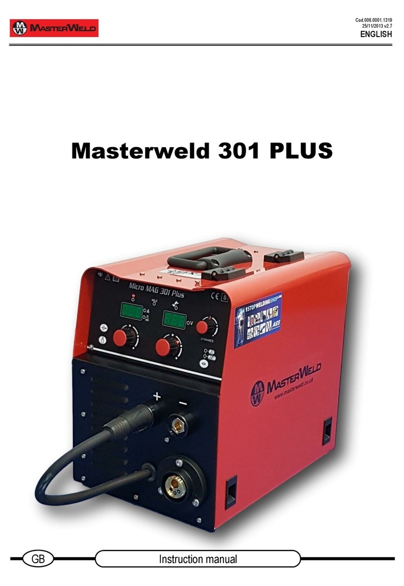
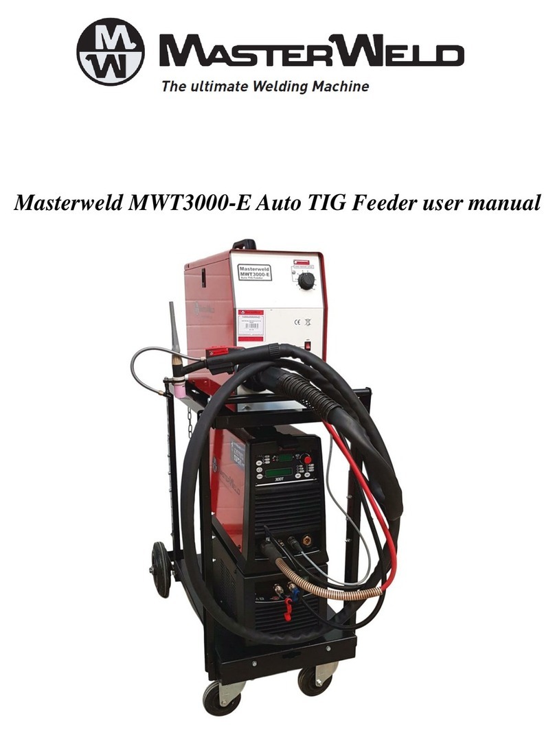
Masterweld Pulse-Expert M-400S User manual

www.masterweld.co.uk
M-400S
M-500S M-600S
Pulse-Expert
OPERATOR MANUAL
ISSUE 1

www.masterweld.co.uk
Welcome
Thank you and congratulations on choosing a MasterWeld product. This Owner’s
Manual is designed to help you get the most out of your welding machine. Please
take time to read the Safety precautions. They will help you protect yourself against
potential hazards in the workplace. With proper maintenance this equipment should
provide years of reliable service.
The entire product range carries the CE mark and is constructed in accordance with
European directives and the product specic standards where they apply.
2

www.masterweld.co.uk
Contents
1.0 Safety Precautions ......................................................... 4
2.0 Product Description ........................................................ 5
3.0 Technical Specifications ................................................ 6
4.0
Description of Controls .................................................. 6
4.1
Symbols and Denitions............................................. 6
4.2
Description of the Machine Wire Feeder ...................7
4.3
Device Control...........................................................8
5.0
Installation ...................................................................... 9
5.1
Unpacking the Machine .............................................9
5.2
Location ....................................................................9
5.3
Input and Grounding Connection ...............................9
5.4
Output Polarity Connections .....................................9
5.5 Torch Cooling ............................................................9
5.6
Maximum Hose Pack Length ....................................9
5.7
Hose Pack Connection ..............................................9
5.8
Gas Testing ............................................................... 10
5.9
Changing Drive Roll Sets ....................................... 10
5.10
Welding Wire Installation ....................................... 10
5.11
Torch Installation ................................................... 11
5.12
Work Return Lead Connection ............................... 11
5.13
Shielding Gas Connection ..................................... 11
6.0
Operation .......................................................................12
6.1
Operation Selecting the JOB ................................. 12
6.2
Operation (2T) ........................................................ 12
6.3
Operation (4T) ........................................................ 12
6.4
Operation (S4T) ..................................................... 12
6.5
Operation Smart Trigger ........................................... 12
6.6
MIG Operation........................................................ 13
6.7
MMA Welding......................................................... 13
6.8
Basic TIG Welding Guide........................................ 14
6.9
Additional Functions .............................................. 14
6.10
List of Jobs and Functions ...................................... 15
7.0 Fault Finding .................................................................19
7.1
Repair and Maintenance ........................................ 21
7.2
Error Codes ........................................................... 22
8.0
Accessories ...................................................................23
8.1
Gas Equipment....................................................... 23
8.2
Feed Rolls .............................................................. 23
9.0
EC Declaration of Conformity ........................................24
9.1
RoHS Compliance Declaration .............................. 24
9.2
WEEE Statement ................................................... 24
9.3
Statement of Warranty ........................................... 25
3

www.masterweld.co.uk
1.0 Safety Precautions
ELECTRIC SHOCK can kill.
Touching live electrical parts can cause fatal shocks or severe burns.
The electrode and work circuit is electrically live whenever the output
is on. The input power circuit and machine internal circuits are also
live when power is on. In semiautomatic or automatic wire welding,
the wire, wire reel, drive roll housing, and all metal parts touching the
welding wire are electrically live. Incorrectly installed or improperly
grounded equipment is a hazard.
Do not touch live electrical parts.
Wear dry, sound insulating gloves and body protection.
Insulate yourself from work and ground using dry insulating mats
or covers big enough to prevent any physical contact with the work
ground.
Additional safety precautions are required when any of the following
electrically hazardous conditions are present: in damp locations
or while wearing wet clothing; on metal structures such as floors,
gratings, or scaffolds; when in cramped positions such as sitting,
kneeling, or lying; or when there is a high risk of unavoidable
or accidental contact with the work piece or ground. For these
conditions, use the following equipment in order presented: 1) a
semiautomatic DC constant voltage (wire) welder, 2) a DC manual
(stick) welder and do not work alone!
Disconnect input power before installing or servicing this equipment.
Lockout/tag out input power according to Safety Standards.
Properly install and ground this equipment according to national and
local standards.
Always verify the supply ground - check and ensure that input power
cable ground wire is properly connected to ground terminal in the
receptacle outlet.
When making input connections, attach proper grounding conductor
first - double-check connections.
Frequently inspect input power cable for damage or bare wiring -
replace cable immediately if damaged - bare wiring can kill.
Turn o all equipment when not in use.
Do not use worn, damaged, under sized, or poorly spliced cables.
Do not drape cables over your body.
If earth grounding of the work piece is required, ground it directly
with a separate cable.
Do not touch electrode if you are in contact with the work, ground, or
another electrode from a different machine.
Use only well-maintained equipment. Repair or replace damaged
parts at once. Maintain unit according to manual.
Wear a safety harness if working above oor level.
Keep all panels and covers securely in place.
Clamp work cable with good metal-to-metal contact to work piece or
worktable as near the weld as practical.
Insulate work clamp when not connected to work piece to prevent
contact with any metal object.
Welding produces fumes and gases. Breathing these fumes and
gases can be hazardous to your health.
FUMES AND GASES can be hazardous.
Keep your head out of the fumes. Do not breathe the fumes.
If inside, ventilate the area and/or use local forced ventilation at the
arc to remove welding fumes and gases.
If ventilation is poor, wear an approved respirator.
Read and understand the Material Safety Data Sheets (MSDS’s) and
the manufacturer’s instructions for metals, consumable, coatings,
cleaners, and degreasers.
Work in a confined space only if it is well ventilated, or while wearing
an air-supplied respirator. Always have a trained watch person
nearby. Welding fumes and gases can displace air and lower the
oxygen level causing injury or death. Be sure the breathing air is
safe.
Do not weld in locations near degreasing, cleaning, or spraying
operations. The heat and rays of the arc can react with vapours to
form highly toxic and irritating gases.
Do not weld on coated metals, such as galvanised, lead, or cadmium
plated steel, unless the coating is removed from the weld area, the
area is well ventilated, and while wearing an air-supplied respirator.
The coatings and any metals containing these elements can give o
toxic fumes if welded.
ARC RAYS can burn eyes and skin.
Arc rays from the welding process produce intense, visible and
invisible (ultraviolet and infrared) rays that can burn eyes and skin.
Sparks fly off from the weld.
Wear an approved welding helmet fitted with a proper shade of lter
lenses to protect your face and eyes when welding or watching
Wear approved safety glasses with side shields under your helmet.
Use protective screens or barriers to protect others from flash, glare
and sparks; warn others not to watch the arc.
Wear protective clothing made from durable, ame-resistant material
(leather, heavy cotton, or wool) and foot protection. Welding on
closed containers, such as tanks, drums, or pipes, can cause them
to blow up. Sparks can fly off from the welding arc. The ying sparks,
hot work piece, and hot equipment can cause fires and burns.
Accidental contact of electrode to metal objects can cause sparks,
explosion, overheating, or fire. Check and be sure the area is safe
before doing any welding.
4

www.masterweld.co.uk
WELDING can cause fire or explosion.
Remove all flammables within 10m of the welding arc. If this is not
possible, tightly cover them with approved covers.
Do not weld where flying sparks can strike flammable material.
Protect yourself and others from flying sparks and hot metal.
Be alert that welding sparks and hot materials from welding can
easily go through small cracks and openings to adjacent areas.
Watch for fire, and keep a fire extinguisher nearby. Be aware that
welding on a ceiling, floor, bulkhead, or partition can cause fire on
the hidden side.
Do not weld on closed containers such as tanks, drums, or pipes,
unless they are properly prepared according to local regulations
Connect work cable to the work as close to the welding area as
practical to prevent welding current from travelling along, possibly
unknown paths and causing electric shock, sparks, and fire hazards.
Cut off welding wire at contact tip when not in use.
Wear oil-free protective garments such as leather gloves, heavy
shirt, cuffless trousers, high shoes, and a cap. Remove any
combustibles, such as a butane lighter or matches, from your person
before doing any welding.
FLYING METAL can injure eyes.
Welding, chipping, wire brushing, and grinding cause sparks and
flying metal. As welds cool they can throw off slag. Wear approved
safety glasses with side shields even under your welding helmet.
BUILDUP OF GAS can injure or kill.
Shut o shielding gas supply when not in use. Always ventilate
confined spaces or use approved air-supplied respirator.
HOT PARTS can cause severe burns.
Do not touch hot parts with bare handed.
Allow cooling period before working on gun or torch.
To handle hot parts, use proper tools and/or wear heavy, insulated
welding gloves and clothing to prevent burns.
MAGNETIC FIELDS can affect pacemakers.
Pacemaker wearers keep away.
Wearers should consult their doctor before going near arc
welding, gouging, or spot welding operations.
NOISE can damage hearing.
Noise from some processes or equipment can damage hearing.
Wear approved ear protection if noise level is high.
Shielding gas cylinders contain gas under high pressure.
CYLINDERS can explode if damaged.
Protect compressed gas cylinders from excessive heat, mechanical
shocks, physical damage, slag, open flames, sparks, and arcs.
Install cylinders in an upright position by securing to a stationary
support or cylinder rack to prevent falling or tipping. Keep cylinders
away from any welding or other electrical circuits. Never drape a
welding torch over a gas cylinder. Never allow a welding electrode to
touch any cylinder. Never weld on a pressurised cylinder - explosion
will result. Use only correct shielding gas cylinders, regulators,
hoses, and fittings designed for the specific application; maintain
them and associated parts in good condition.
Turn face away from valve outlet when opening cylinder valve.
Use the right equipment, correct procedures, and sufficient number
of persons to lift and move cylinders.
Read and follow instructions on compressed gas cylinders,
associated equipment, and Compressed Gas Association (CGA).
2.0 Product Description
The MasterWeld M-400S, M-500S and M-600S are complete
semiautomatic constant voltage DC arc welding machine built to meet
CE specifications. It combines a constant voltage power source and a
constant speed wire feeder with a microcomputer-based controller to
form a reliable high-performance welding system. A simple control
scheme, consisting of voltage and wire feed speed controls, provides
versatility with ease of use and accuracy. Other features include wire
reel spindle with adjustable brake for 15kg wire spools (300mm), an
integral gas cylinder mounting undercarriage, an adjustable Argon flow
regulator with cylinder pressure gauge and inlet hose, a MIG torch, and
a 3.0m work cable with clamp.
5

www.masterweld.co.uk
3.0 Technical Specications
4.0 Description of Controls
4.1 Symbols and Denitions
1. Manual Metal Arc welding
2. TIG welding
3. MIG welding
4. Self-shielded flux-core arc welding
5. Submerged arc welding
6. Plasma cutting
7. Arc gouging
8. Plasma welding
9. Direct current
10. Alternating current
11. Accurate or alternating current at the same output
and additional frequency of Hz
12. Single-phase transformer
13. Three phase transformer with rectifier
14. Single or three-phase static frequency inverter -
transformer - rectifier
15. AC or DC Inverter power supply
16. Three-phase motor - generator
17. Three-phase motor - generator - rectifier
18. Three-phase rotary frequency inverter
19. Single-phase combined AC and DC power unit
20. Internal combustion engine - generator
21. Internal combustion engine - generator – rectifier
22. Supply circuit, number of phases (e.g. 1 or 3), alternating
current symbol and declared frequency (e.g. 50 Hz or 60 Hz)
23. Internal combustion engine
24. Motor
25. Belt drive
26. Amps
27. Voltage
28. Voltage input
29. Voltage output
30. Positive
31. Negative
32. Open circuit voltage
33. Mains voltage
34. Load voltage
35. Maximum current drawn from the supply
36. Maximum line current under load
37. Welding current under load
38. Percent
39. Suitable for environments with increased risk of electric shock
40. Hertz
41. Temperature
42. Increment / Decrease setting
43. Duty Cycle
44. On
45. Off
The MasterWeld M-400S, M-500S and M-600S are separate types of machine with
separate wire feed units for use with three phase 400V supply. The machine uses
inverter technology to allow MIG, TIG and MMA welding to be performed.
6

www.masterweld.co.uk
4.2 Description of the Machine Wire Feeder
1. Handle
2. Welding Torch Connection
3. Machine Feet mounting locations
4. Connection Socket for electrode
5. Cooling water back ow connection (Red)
6. Cooling water forward ow connection (Blue)
7. Welding machine control panel and protective cover
8. Welding wire Plastic Cover
9. Wire feed box door
10. Plastic Front protector
Rear View
1. Connection (Trigger) socket
2. Communication socket
3. Power supply welding current connection socket
4. Coolant back ow connection (Red)
5. Cooling water forward ow connection (Blue)
6. Gas connection
7. Support Bush
Internal View
1. Wire spool protective cover
2. Wire spool hub
3. Wire feed box
4. Wire loading button
5. Gas test button
6. Wire-feed door
Wire Feed Unit Front Panel
1. Welding Torch
2. Welding Torch hose package
3. Welding torch connection
4. Connection Socket for MMA welding
5. Cooling water back ow (Red)
6. Cooling water flow forward (Blue)
7

www.masterweld.co.uk
4.3 Device Control
8
12
13
14
910 11
12
13
14
6 15 16 17

www.masterweld.co.uk
5.0 Installation
Read entire installation section before starting installation.
SAFETY PRECAUTIONS
•
ELECTRIC SHOCK can kill.
•
Only qualified personnel should perform this installation.
•
Only personnel that have read and understood the Operating
Manual should install and operate this equipment.
•
Machine must be grounded per any national, local or other
applicable electrical regulations.
•
The MIG power switch is to be in the OFF position when installing
work cable and torch and when connecting other equipment.
5.1 Unpacking the Machine
Cut banding and lift off cardboard carton. Cut banding holding the
machine to the skid. Remove corrugated packing material. Remove
accessories from Gas Bottle Platform. Roll the machine o the skid.
5.2 Location
Locate the welder in a dry location where there is free circulation of
clean air into the louvres in the back and out the front. A location that
minimises the amount of smoke and dirt drawn into the rear louvres
reduces the chance of dirt accumulation that can block air passages
and cause overheating.
5.3 Input and Grounding Connection
WARNING
Before starting the installation, check that your power supply
is adequate for the voltage, amperage, phase, and frequency
specified on the Machine nameplate.
The 400 volt 50 Hz machine is supplied with a 3m input cable and
without plug, ensure that you connect a plug that is suitably rated for
the power draw of the machine and the environmental location.
Have a qualified electrician connect the input plug. For long runs
over 30m, larger copper wires should be used. The green/yellow
wire in the input cable connects to the frame of the machine. This
ensures proper grounding of the machine when the machine plug is
inserted into the receptacle.
5.4 Output Polarity Connections
MIG, TIG and MMA welding use different electrode polarities. The
polarity of the MIG torch can be selected by connection of the torch
cable to the + or - socket the front of the welder, (+) polarity. This is
the normal polarity for MIG welding with GAS.
5.5 Torch Cooling
Coolant liquids!
The use of unsuitable coolants will result in damage and void the
manufacturer’s warranty!
•
Only use the coolants specified in this manual.
•
Do not mix different coolants.
•
Replace the entire fluid when changing the coolant.
Insufficient antifreeze in the welding torch coolant can damage the
machine. The coolant must be checked at regular intervals for the
amount of antifreeze and thus avoid any damage to the machine and
its accessories.
Only use MasterWeld coolant
5.6
Maximum Hose Pack Length
The maximum length of the intermediate hose package is 40 m due
to the cooling pump operating pressure.
WARNING
•
The welding power cables that are improperly installed can cause
faults on the arc!
•
The hose package and the work piece return cable should be
routed as long as possible, adjacent and parallel.
•
In order to avoid mutual interactions. Observe the minimum
distance of 20 cm.
•
Cable lengths should not be longer than required. Maximum
30 m for ideal welding results. (Work piece + intermediate hose
package + torch line).
•
Use a separate work return cable for each welding machine.
•
Fully uncoil welding current lines, welding torches and
intermediate hose packages.
•
Cable lengths should not be longer than required.
5.7
Hose Pack Connection
1. Power Source
2. Intermediate Hose Package
3. Cable Clamp
4. Power supply welding current connection socket
5. Shielding gas connection
6. Cooling water back ow (Red)
7. Cooling Water flow forward (Blue)
8. Connection (Trigger) socket
9. Communication socket
•
The hose package end should be passed through the
intermediate hose package tensioner and fastened as indicated
by the cable clamp belt.
•
Insert the welding current wiring connector into the “welding
current connection socket” and lock it by turning to the right.
•
Install the cover nut of the shielding gas line to the G¼ Thread
fitting.
•
Insert the cable connector of the control line into the connection
socket and secure with the nut (the socket can only be inserted
into the connection socket in one position).
•
Fit the connection of the coolant hoses to the appropriate quick
couplings: red (coolant back ow) to the quick connector and blue
quick connector (coolant supply).
9

www.masterweld.co.uk
ATTENTION
Machine damage can be caused by improperly connected
coolant lines!
In the case of improperly connected coolant lines or if a gas-cooled
welding torch is used, the cooling circuit is interrupted and machine
damage may occur.
•
Connect all cooling lines properly!
•
Complete the hose package and the torch hose package.
•
Pay attention to the maximum hose package length!
•
If using a gas-cooled welding torch, disconnect the cooling unit
at the rear of the machine.
5.8
Gas Testing
•
Open the gas cylinder valve slowly.
•
Open the pressure reducer.
•
Switch on the power supply from the main switch.
•
Press the gas test function on the wire feeder.
•
Adjust the amount of gas in the ow meter according to
the application.
•
The gas test is activated by briefly pressing the button on the wire
feed unit. The shielding gas flows for about 25 seconds or until
the button is pressed again.
Setting the amount of shielding gas welding method recommended
amount of shielding gas
MAG welding Wire diameter x 11.5 = l / min
MIG brazing Wire diameter x 11.5 = l / min
MIG welding (aluminium) Wire diameter x 13.5 = 1 / min
(100% argon) Gas nozzle diameter in TIG mm is equal to 1 / min
gas ow
Incorrect protective gas adjustment!
A too low or too high a shielding gas setting can cause air to reach
the welding pool, resulting in the formation of pores.
•
Adjust the shielding gas amount according to the welding task!
Source information display.
The “Parameter selection” keys are located on the left and right of
the machine control unit. These keys are used to select the source
parameters shown.
Each time the button is pressed, the display changes to the next
parameter (the LED's next to the key indicate the selection). Once
the last parameter is reached, the first parameter is restarted.
The following are shown.
•
Nominal Values (Before welding)
•
Actual Values (During welding)
•
Hold values (After welding)
5.9
Changing Drive Roll Sets
1. Turn off the power source.
2. Release the pressure on the idle rolls by swinging the adjustable
pressure arm down. Lift the cast idle roll assembly and allow it to
sit in an upright position.
3. Unscrew the plastic knob retaining the lower grooved drive roll
and side off the drive roller
4. Ensure the wire size marked on the side of the feed roller
matches the wire size to be used.
5. Replace the drive rolls in reverse of the above procedure
ensuring the wire size to be used is marked on the outward facing
side of the roller as it is refitted.
NOTE:- Be sure that the torch liner and contact tip are also
sized to match the selected wire size.
5.10
Welding Wire Installation
As a factory delivery, the Euro connection is equipped with a
capillary tube for welding torches with spiral liners. If a welding torch
with plastic liner is used the capillary tube should be removed.
•
Use a steel guide tube to weld hard, unalloyed wire electrodes
(steel).
•
Use a chrome nickel guide spiral to weld hard, high-alloyed wire
electrodes (CrNi).
•
Use extension of torch liner for welding or soldering soft wire
electrodes, high-alloy wire electrodes or aluminium materials.
Preparation for connecting welding torches with manual spirals:
•
Check that the central connection is seated in the capillary tube!
Preparations for the connection of welding torches with torch liner
extension.
•
Push the capillary tube forward in the direction of the central
connection by the wire feed and remove it here.
•
Shorten the liner extension just before the wire feed roller with the
a knife.
•
Loosen the centre socket of the welding torch and pull it out.
•
Clean and sharpen the separated end of the wire liner
•
Open the wire drum cover by pulling down and out on the bottom
of the cover
•
Unscrew the plastic retaining wheel from the end of the spool
holder shaft.
•
Position the wire spool so that it will rotate in a direction when
feeding so as to be dereeled from the bottom of the coil.
•
Slide the wire spool all the way onto the shaft and refit the plastic
retaining nut.
NOTE:- There is a friction brake on the reel hub assembly,
to prevent the wire spool over running. When welding stops
ensure the nut is slackened to the minimum setting. It can be
adjusted by means of the nut visible when the plastic nut is
removed.
•
Turn the Spool until the free end of the electrode is accessible.
While securely holding the electrode, cut o the bent end and
straighten the first six inches. (If the electrode is not properly
straightened, it may not feed properly through the wire drive
system. Manually feed the wire from the wire reel and through the
wire guide and then over the top of the wire feed rollers (ensure
the pressure arms are in the raised position).
•
Continue to feed the wire through the outlet guide until 20mm of
wire is protruding from the front of the machine torch connector.
•
Re-position the adjustable pressure arms to there original position
to apply pressure. Adjust pressure as necessary.
NOTE:- The pressure arm should be adjusted in order to give
the minimum amount of pressure on the wire to allow reliable
feeding.
10

www.masterweld.co.uk
Fig 1
5.11
Torch Installation
•
Insert the Euro connector of the welding torch into the Euro
socket and screw tight with the hand nut.
•
Fit the coolant hoses to the appropriate quick couplings: red
(coolant back ow) and blue (coolant supply).
Wire feed
Opening the door of the wire feeder drive
CAUTION
The door of the feed system must be opened for the following
operations. The door must be closed again before starting work.
Loading the wire to the feed unit
CAUTION Risk of injury due to moving parts!
Wire feeders are equipped with moving parts that can trap hands,
hair, clothes or tools and thus injure people!
•
Do not handle rotating or moving parts or drive parts by hand!
•
Keep the protective covers closed during operation! Risk of injury
due to uncontrolled welding wire!
The welding wire can be feeding at high speed and can get out of
control and injure people in the case of improper or incomplete wire
feeding!
•
Ensure full wire delivery from the wire coil to the welding torch
before connecting to the mains!
•
If the welding torch is not installed, unscrew the rollers of the wire
feeder!
•
Check the wire delivery at regular intervals!
•
Keep all body covers and protective covers closed during
operation!
Risk of injury due to welding wire feeding from the welding torch!
The welding wire can overflow the welding torch with a high speed
and injure face and eyes with body parts!
•
Never point the welding torch to your body and to the bodies of
others!
ATTENTION
The wear on the wire feed rollers increases due to unsuitable roller
pressure!
•
In the setting nuts of the pressurised pressure units, it must be
adjusted so that the wire electrode is stopped, but only when the
wire feed is blocked!
•
Adjust the press pressure of the front rollers (when viewed in the
push direction) higher!
•
The transmission speed can be infinitely adjustable by pressing
the wire feed button and also by rotating the wire feed speed
rotary knob. The selected feed rate is shown on the left displayof
the wire feed unit.
•
Extend the torch straight while loading wire .
Your MasterWeld MIG/MAG Welding Torch has been supplied
ready to weld. It has been supplied with the standard consumables
denoted in the product brochure.
To connect the torch to the power source:-
1. Remove the tip adaptor and contact tip
2. Inch the wire from the exit of the wire guide on the feed unit
as Figure 1. Ensure that it does not short out on any machine
panels.
Fig 2
3. Carefully slide the electrode wire into the torch liner and slowly
locate the torch gun plug body into the feed unit central connector
and tighten the gun plug nut as Figure 2
NOTE:- To aid the initial location of a new torch and to prevent
damage to the gas nipple O Ring a very light application of
grease to the O Ring is beneficial.
4. Keeping the torch as straight as possible, use the power source
inch facility or torch trigger to feed the electrode wire 50mm from
the end of the liner conduit.
5. Once the electrode wire has stopped, refit the tip adaptor,
diuser, contact tip and gas nozzle.
6. Trim the electrode wire to within 5mm of the face of the nozzle,
this will facilitate jolt free arc initiation.
7. Press the gas purge button and check the gas flow is adequate
for your application.
8. An inexpensive flow meter is available from MasterWeld
9. If you are setting a water-cooled torch ensure you have the
recommended water flow rate.
NOTE:- It is essential to ensure adequate flow of clean, cool
water to prevent irreparable torch failure, a minimum of 1.2 l/
min is recommended.
Note. Water flows into the torch through the blue hose. The blue
hose delivers cold water directly to the prime source of heat, the
swan neck and consumable. The re circulated water is then passed
through the torch power cable to cool the power cable as it is
returned to the cooler through the red water return lead.
Ensure all air is removed from the water cooling circuit before
welding.
5.12
Work Return Lead Connection
Insert the work return lead connector into the receptacle on the front
panel of the machine and twist it clockwise until tightly secured.
Connect the earth clamp to the work piece as close as possible to
the point to be welded and ensure that a good electrical connection
is created to bare metal.
5.13
Shielding Gas Connection
1. Using the gas hose supplied connect the hose to the gas inlet
connection on the rear of the machine and tighten it with a
spanner.
2. Connect the opposite end of the gas hose to the output
connection of a gas regulator capable of supplying the correct
gas ow for the welding operation.
NOTE:- If the gas cylinder is to be stored on the back of
the machine ensure it is secured using the retention chain
provided.
11

www.masterweld.co.uk
6.0 Operation
Switch on the machine using the mains on/off switch, this lights the
front panel.
You can MIG weld in 2 modes Manual and Synergic the manual
mode takes more skill to setup.
Synergic MIG
•
Select the Synergic MIG mode using button
6.1 Operation Selecting the JOB
Press and hold JOB button for 5 seconds (7) until the left display
says JOB rotate the right hand knob until the correct JOB number is
displayed. Refer to the inside of the wire feeder door for lob list.
Note Job list is shorter with Rapid panel and you should select
material and wire size on the front panel using buttons 10 and 11.
Adjusting the Function. Press and hold the F button (3) for 5 seconds
and the left display will show the F number which can be adjusted
by rotating the left knob 4 and the value will be displayed in the right
display and can be adjusted with the right hand knob.
Press the F button (3) briefly to display wire speed, material
thickness or Amperage depending on your preference and then
rotate the left knob (4) until you reach the required value. You are
ready to weld, If you prefer to alter the welding voltage you can trim
it up or down by rotating the right knob (8) and the V+/- light will
illuminate.
Switch o the synergic light or with Rapid panel toggle o the using
F function.
Manually adjust the Wire speed and welding voltage using the rotary
knobs 4 and 8. Note in manual mode you must adjust the voltage
to increase or reduce penetration and the wire speed to balance
the heat input. (Synergic mode is preferred for operation in all
operations)
6.2 Operation (2T)
Select 2T operation on the front panel.
•
Depress the trigger and hold on.
•
Pre-gas will start (adjust with F30)
•
Then arc will start
•
At the end of the weld release the trigger and the arc stops.
•
The wire stick out can be adjusted by changing burn back time
(F41)
•
The post gas flow can be adjusted as required (F43)
12
6.3 Operation (4T)
Select 4T operation on the front panel
•
Depress the trigger and hold
•
Pre-gas will start and stay on
•
Release the trigger the arc will start and continue
•
At the end of the weld depress and hold the trigger, the final
current will start (F39) and will stay on until the trigger is
released which starts post gas (F43)
6.4 Operation (S4T)
Select 4T operation on the front panel
•
Depress the trigger and hold
•
Pre-gas will start and stay on (F30)
•
Hot start current will start (F32)
•
Release the trigger the arc will change to the normal power level
and continues
•
At the end of the weld depress and hold the trigger, the final
current will start (F39) and will stay on until the trigger is released
which starts post gas (F43)
6.5 Operation Smart Trigger
Smart trigger allows the user to change memory programs quickly
from the torch without having to return to the machine. Store the
required programs starting at memory location 01, 02 etc.
Using F47 set the number of memories you wish to use for smart
trigger. If you wish to use 4 different settings in memory 01, 02, 03
and 04 then set F47 value to 04 and smart trigger will only cycle
through memory 01 to 04.
Ensure the front panel of the machine is set to 4T or S4T operation.
Set the value of F46 to 01 to switch on smart trigger.
Now if you give the trigger a short press (less than 1 second) it will
select the next memory program within the limit set by F47. Another
short press moves to the next memory location etc.
I

www.masterweld.co.uk
6.6 MIG Operation
Note:- Check that drive rolls, and torch parts are correct for the
wire size and type being used.
1. The optimum idle roll pressure varies with type of wire, wire
diameter, surface conditions, lubrication, and hardness. As a
general rule, hard wires may require greater pressure, and soft,
or aluminium wire, may require less pressure than the factory
setting. The optimum idle roll setting can be determined as
follows:
2. Press end of gun against a solid object that is electrically isolated
from the welder output and press the gun trigger for several
seconds.
3. If the wire “bird nests”, jams or breaks at the drive roll, the idle
roll pressure is too great. Back the adjustment knob out 1/2 turn,
run new wire. If the only result was drive roll slippage, loosen
the Hand nut on the central connector and pull the gun forward
about 6” (15cm) away from the power source. There should be a
slight waviness in the exposed wire. If there is not waviness, the
pressure is too low. Tighten the adjustment knob 1/4 turn, reinstall
the gun cable and repeat the above steps.
4. When triggering, the electrode and drive mechanism are
electrically “LIVE” relative to work and ground and remain “LIVE”
several seconds after the gun trigger is released.
WARNING
When using an open arc process, it is necessary to use correct
eye, head, and body protection.
5. Position wire over joint. The end of the wire may be lightly
touching the work.
6. Lower welding helmet, operate gun trigger, and begin welding.
Hold the gun so the contact tip to work distance is about 3/8”
(10mm).
7. To stop welding, release the gun trigger and then pull the gun
away from the work after the arc goes out.
8. When no more welding is to be done, close valve on gas cylinder
(if used), momentarily operate gun trigger to release gas pressure
and turn o the machine.
NOTE:- These settings are guidelines only. Material and wire
type, joint design, fit up, position, shielding gas, etc. affect
settings. Produce test welds to be sure they comply
to specifications.
Welding circuit calibration.
The welding circuit resistance can vary, but the machine can be
set to compensate for this. Cut the welding wire flush with the front of
the contact tip and remove the outer nozzle. Select F60 from
the function menu while holding the contact tip firmly against the
work piece. Press the trigger three to ve times for approximately 1
second to calibrate the circuit resistance. The correction figure will
be shown in the PH display (millivolts).
Material thickness determines weld parameters.
1. Convert Material Thickness to Amperage (A) (0.25mm= 1Amp)
3.2mm = 125 A
2. Select Wire Size
Amperage Range Wire Size
40 - 145 A 0.8 mm
50 - 180 A 1.0 mm
75 - 250 A 1.2 mm
3. Select Wire Speed (Amperage)
Wire Size Feed speed
0.8 mm 0.05m/min per Amp
1.0 mm 0.04m/min per Amp
1.2 mm 0.025m/min per Amp
So based on 3.2 mm material thickness amperage should be 125A
if using 1.0mm wire then the wire feed speed should be
0.04 X 125= 5m/min
Wire speed (amperage) controls weld penetration
4. Select Voltage. Voltage controls height and width of weld bead
Low Voltage: wire stubs into work
High Voltage: arc is unstable (spatter)
Set voltage midway between high/low voltages.
And then fine tune accordingly
6.7 MMA Welding
Output Polarity Connections
Electrode polarity
MMA electrodes are generally connected to the ‘+’ terminal and the
work lead to the ‘-‘terminal
The twist connector on the wire feeder is a + outlet.
But if in doubt consult the electrode manufacturer’s literature.
MMA Welding Operation
WARNING
When using an open arc process, it is necessary to use correct
eye, head, and body protection.
MMA Welding Guide
Select JOB 7 and the left display will show the amperage and the
right display will show "EL". You can adjust the welding amperage
using the left-hand knob (4) you can alter the MMA Arc force, Hot
start, Arc Force. Using F70, F71, F72.
Effects of MMA welding various materials
High tensile and alloy steels
The two most prominent effects of welding these steels are the
formation of a hardened zone in the weld area, and, if suitable
precautions are not taken, the occurrence in this zone of under-bead
cracks. Hardened zone and under-bead cracks in the weld area may
be reduced by using the correct electrodes, preheating, using higher
current settings, using larger electrodes sizes, short runs for larger
electrode deposits or tempering in a furnace.
Manganese steels
The effect on manganese steel of slow cooling from high
temperatures is embrittlement. For this reason, it is absolutely
essential to keep manganese steel cool during welding by
quenching after each weld or skip welding to distribute the heat.
Cast iron
Most types of cast iron, except white iron, are weldable. White iron,
because of its extreme brittleness, generally cracks when attempts
are made to weld it. Trouble may also be experienced when welding
white-heart malleable, due to the porosity caused by gas held in this
type of iron.
13

www.masterweld.co.uk
Copper and alloys
The most important factor is the high rate of heat conductivity of
copper, making preheating of heavy sections necessary to give
proper fusion of weld and base metal.
Types of electrodes
Arc welding electrodes are classified into a number of groups
depending on their applications. There are a great number of
electrodes used for specialised industrial purposes which are not of
particular interest for everyday general work. These include some
low hydrogen types for high tensile steel, cellulose types for welding
large diameter pipes, etc. The range of electrodes dealt with in this
publication will cover the vast majority of applications likely to be
encountered; are all easy to use and all will work on even the most
basic of welding machines.
Metals Being Joined and
Electrode Comments
Mild steel
6013 ideal electrodes for all general-purpose work. Features include
outstanding operator appeal, easy arc starting and low spatter.
Mild steel
7014 all positional electrode for use on mild and galvanised steel
furniture, plates, fences, gates, pipes and tanks etc. Especially
suitable for vertical down welding.
Cast iron
99% nickel suitable for joining all cast irons except white cast iron
Stainless steel
318l-16 high corrosion resistance. Ideal for dairy work, etc.
On stainless steels vertical, lift the torch up from the work piece to
draw out an arc. To prevent melting of the end of the tungsten so this
in a smooth rapid movement
TIG welding guide ranges.
6.8 Basic TIG Welding Guide
TIG welding cable connection
Connect the TIG torch to the - terminal and the work lead to the +
terminal for direct current straight polarity. Direct current straight
polarity is the most widely used polarity for DC TIG welding. It allows
limited wear of the electrode since 70% of the heat is concentrated
at the work piece. Connect the gas hose on the TIG torch to the gas
outlet on the gas regulator. Move the selector switch on the front
panel of the machine to the LIFT-TIG position.
Torch starting in LIFT-TIG mode
To operate in TIG welding mode select JOB 6 on the right control
and the left display will show amperage and the right display will
show TIG. You can adjust the welding amperage with the left control.
Ensure the gas supply is switched on and gas is owing from the
front of the torch nozzle. Briefly contact the tip of the tungsten
electrode down onto the work piece with the torch at around 70º
from vertical, lift the torch up from the work piece to draw out an arc.
To prevent melting of the end of the tungsten so this in a smooth rapid
movement.
6.9 Additional Functions
6.9.1 Memory function
RAPID panel has 3 memory location available which can be
selected using button 5
PRO panel has up to 100 memory locations available. The number
of memory locations available to the use can be set.
Auto save is enabled by default and after adjusting any of the
parameters the memory display will flash to show it is saved.
Altering the number of memory locations available (PRO panel).
Press and hold the F button for 5 seconds. Select F45 and increase
or decrease the number of memory locations to suit the user.
Switching o Auto Save. Press and hold the F button for 5 seconds.
Select F44 and set the value to zero. With auto save o it is now
required to press and hold the down button (5) until the memory
display goes out which confirms the save. You can switch on
Auto save again by setting the value of F44 to 01.
6.9.2 Supervisor Lock
It is possible to set the machine in lock mode so that the operator
can only use JOBs that have been saved to memory. To activate the
lock function first program the machine as required for the user and
then follow the following steps to activate the lock.
Switch o the machine press the mem down arrow (5) and hold
while switching on the machine until you see LOC on the display
and then rotate the right hand knob so the value is 01 (On). It will
now not be possible to adjust any parameter other than the memory
location and the voltage trim.
To remove the lock switch o the machine press the mem down
arrow (5) and hold while switching on the machine until you see
LOC on the display and then rotate the right hand knob so the value
is 00 (Off).
6.9.3 Pulse Balance Adjustment
The standard preset double pulse function should be suitable for all
applications but if you need to change the double pulse parameter
you can do so as detailed below
Using the F functions F35, F36, F37 and F38
F35 is the time spent and the peak (normal) power level and can be
adjusted from 0 to 2.0 Seconds. Increasing this parameter will give
increased heat input and a wider spread of the weld pool.
F36 is the difference between the normal power level and the low
power level. It can be adjusted from 0 to 50% at 50% the low power
level will be 50% less than the normal power level.
F37 is the time spent and the base (low) power level and can be
adjusted from 0 to 2.0 Seconds. Increasing this parameter will give
reduced heat input
F38 is the voltage trim for the base current level and can be adjusted
+/- 0 to 9.9 volts
14

www.masterweld.co.uk
TIG Welding Guide Ranges
Electrode diameter DC current (amps)
0.040" (1.0mm) 30 – 60
1/16" (1.6mm) 60 – 115
3/32" (2.4mm) 100 – 165
Tungsten Electrode Types
Electrode
type Welding application Colour
code
Thoriated
2%
DC welding of mild steel, stainless
steel and copper. Excellent arc
starting, long life, high current
carrying capacity.
RED
Ceriated
2%
DC welding of mild steel, stainless
steel, copper, aluminium, their alloys
longer life, more stable arc, easier
starting, wider current range, narrower
more concentrated arc
GREY
Guide for Selecting Filler Wire Diameter
Filler wire
diameter DC current range
1/16" (1.6 mm) 20 - 90
3/32" (2.4 mm) 65 - 115
1/8" (3.2 mm) 100 - 165
3/16" (4.8 mm) 200 - 350
The filler wire diameter specified is a guide only, other diameter
wires may be used according to the welding application.
Shielding Gas Selection
Alloy Shielding gas
Aluminium & alloys Pure Argon
Carbon steel Pure Argon
Stainless steel Pure Argon
Nickel alloy Pure Argon
Copper Pure Argon
Titanium Pure Argon
15
6.9 List of Jobs and Functions

www.masterweld.co.uk
The all-new MasterWeld M-400S, M-500S and M-600S offer an extensive selection of synergic MIG programs available to
the welding industry covering a wide range of materials and welding processes. Please choose from the below list of Jobs
that have been written for these materials to ensure you are using the correct job for material, wire diameter and shielding
gas.
16

www.masterweld.co.uk
17

www.masterweld.co.uk
Function Description Min Max Unit
F30 Pre-gas 0 5.0 Seconds
F31 Creep Start On / O 0 1 O / On
F32 Hot Start 30 200 %
F33 Hot Start Voltage Correction -9.9 +9.9 Volts
F35 Double Pulse Program Peak Time 0 2.0 Seconds
F36 Double Pulse % Delta Feed 0 50 %
F37 Double Pulse Program Base Time 0 2.0 Seconds
F38 Double Pulse - Lower Arc Correction -9.9 +9.9 Volts
F39 Crater Fill 30 100 %
F40 Crater Fill Arc Correction -9.9 +9.9 Volts
F41 Burn Back Control 0 15 Range
F42 Wire Stick-Out 0 15 Range
F43 Post Gas 0 5.0 Seconds
F44 Auto Save 0 1 O / On
F45 Memory Limit 0 100 Qty
F46 Smart Trigger 0 1 O / On
F47 Smart Trigger Limit 0 100 Qty
F48 Spot Time 0 20 Seconds
F60 Load Resistance Calibration 0 0.30 Ohm
F25 Hot Start 100 350 %
F26 Hot Start Time 0 2 Seconds
F27 Arc Force 0 400 %
TIG
F10 Water Cooling Unit 0 1 O/On
Function Table
MIG/MAGMMA
18

www.masterweld.co.uk
7.0 Fault Finding
Problem Cause/Corrective Action
Porosity - small cavities or holes.
Resulting from gas pockets in
weld metal.
Inadequate shielding gas
coverage. Check for proper
gas ow rate.
Remove spatter from gun
nozzle.
Check gas hoses for leaks.
Eliminate drafts near welding
arc.
Place nozzle 6-13 mm from
work piece Hold gun near
bead at end of weld until
molten metal solidifies.
Wrong gas. Use welding
grade shielding gas; change to
different gas.
Dirty welding wire. Use clean,
dry welding wire. Eliminate
pickup of oil or lubricant on
welding wire from feeder or
liner.
Work piece dirty. Remove all
grease, oil, moisture, rust,
paint, coatings, and dirt from
work surface before welding.
Use a more highly deoxidizing
welding wire (contact supplier).
Welding wire extends too far
out of nozzle.
Be sure welding wire extends
not more than 13 mm beyond
nozzle.
Problem Cause/Corrective Action
Incomplete fusion to base metal. Work piece dirty. Remove all
grease, oil, moisture, rust,
paint, coatings, and dirt from
work surface before welding.
Insufficient heat input. Select
higher voltage range and/or
adjust wire feed speed.
Improper welding technique.
Place stringer bead in proper
locations) at joint during
welding.
Adjust work angle or widen
groove to access bottom
during welding.
Momentarily hold arc on
groove side walls when using
weaving technique.
Keep arc on leading edge of
weld puddle. Use correct gun
angle of 0 to 15 degrees.
Excessive Penetration – weld
metal melting through base
metal and hanging underneath
weld.
Excessive heat input. Select
lower voltage range and
reduce wire feed speed.
Increase travel speed.
Lack Of Penetration - shallow.
Fusion between weld metal and
Base metal.
Improper joint preparation.
Material too thick. Joint
preparation and design must
provide access to bottom of
groove while maintaining.
Proper welding wire extension
and arc characteristics.
Improper weld technique.
Maintain normal gun angle of
0 to 15 degrees to achieve
maximum penetration. Keep
arc on leading edge of weld
puddle. Ensure welding wire
extends not more than 13 mm
beyond nozzle.
Insufficient heat input. Select
higher wire feed speed and/or
select higher voltage range.
Reduce travel speed.
Burn-Through - weld metal
melting.
Completely through base metal.
Resulting in holes where no
metal remains.
Excessive heat input. Select
lower voltage range and
reduce wire feed speed.
Increase and/or maintain
steady travel speed.
19

www.masterweld.co.uk
20
Problem Cause/Corrective Action
Excessive Spatter - scattering of
Molten metal particles that cool
to solid form near weld bead.
Wire feed speed too high.
Select lower wire feed speed.
Voltage too high. Select lower
voltage range.
Electrode extension (stick out)
too long. Use shorter electrode
extension (sick out).
Work piece dirty. Remove all
grease, oil, moisture, rust,
paint, undercoating, and dirt
from work surface before
welding.
Insufficient shielding gas at
welding arc. Increase flow of
shielding gas at regulator/flow
meter and/or prevent drafts
near welding arc.
Dirty welding wire. Use clean,
dry welding wire. Eliminate
pickup of oil or lubricant on
welding wire from feeder or
liner.
Wire feed unit operates but no
gas ow.
Gas cylinder empty.
Gas regulator closed.
Faulty solenoid.
Restriction in torch cables.
Wire feed unit operates, but
does not feed.
Insufficient drive roll pressure.
Incorrect drive rolls.
Excessive wire spool brake
tension.
Incorrect liner.
Blocked liner.
Bird nesting.
Burn back.
Bird nesting. Excessive feed roll pressure.
Incorrect or blocked liner.
Incorrect contact tip size.
Contact tip overheating.
Restriction in torch cable.
Misaligned drive rolls or wire
guides.
Excessive cable kinks.
Burn back. Improper voltage setting.
Improper stick out.
Erratic wire feed.
Incorrect or blocked liner.
Contact tip overheating.
Excessive cable kinking.
Problem Cause/Corrective Action
Erratic Wire Feeding or Arc. Improper drive roll tension.
Improper drive roll size.
Worn drive rolls.
Incorrect or blocked liner.
Incorrect wire guide size.
Misaligned drive rolls or wire
guide.
Gaps at liner or wire guide
junctions.
Incorrect contact tip size.
Contact Tip overheating.
Spatter adhesion on exit
geometry of tip bore.
Excessive cable kinkage.
Poor earth or cable
connections.
Weld joint area dirty.
Yellow temperature light
illuminates.
Power source has over heated
leave the machine running
to allow it to cool down.
Ensure entry and exit vents
on machine are clear and
machine has a good supply of
cooling air.
Reduce operating duty cycle
and or amperage.
This manual suits for next models
2
Table of contents
Other Masterweld Welding System manuals