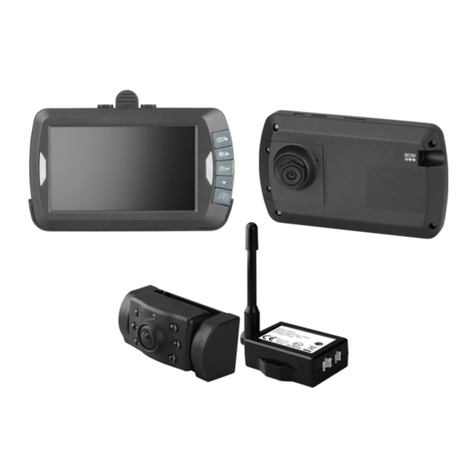
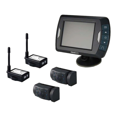
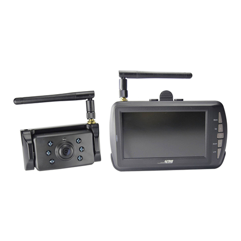
pro user DRC4340 User manual

D
D
IGIT
A
DIGI
TA
SYST
E
DIGI
T
A
LWI
R
TA
LES
K
E
ME
D
T
ALE
D
w
m
R
ELES
S
K
ABEL
L
ECA
M
N
U
D
RAAD
w
ith10,
9
m
it10,9
avecéc
r
m
et10,
9
S
BAC
K
L
OSES
SYST
E
M
ERA
D
U
MERI
Q
LOOS
9
cm/4.
3
cm/4,3
ran10,9
c
9
cm/4,
3
DRC43
4
K
‐UPC
A
RÜC
K
E
M
D
ERE
C
Q
UE
CAM
E
3
”moni
t
”Monit
o
c
m/4,3
”
3
”monit
o
4
0
A
MER
A
FAHR
K
C
ULS
A
E
RASY
S
t
or
o
r
”
o
r
A
SYS
T
K
AME
R
A
NSFI
L
S
TEE
M
T
EM
R
A‐
L
M

2
INTRODUCTION
ThePro‐UserDRC4340isamemberofthefamilyofadvancedcarback‐upsystems
manufacturedbyProUserInternationalLtd.
ThePro‐UserDigitalBack‐upCameraandMonitorwithbuiltintransmitterbox,when
usedasdescribed,willimproveyourabilitytoseebehindyourcar,camper,trailer,or
mini‐van.Wehavetakennumerousmeasuresinqualitycontroltoensurethatyour
productarrivesintopcondition,andwillperformtoyoursatisfaction.
Pleasecarefullyreadandfollowthefollowingsafetyandoperatinginstructions.
IMPORTANTSAFETYINSTRUCTIONS
BeforeYouInstall
Ifyouarenotconfidentworkingwith12V/24VDCvehiclewiring,removingand
reinstallinginteriorpanels,carpeting,dashboardsorothercomponentsofyourvehicle,
contactthevehicle’smanufacturer,orconsiderhavingthecamerasystemprofessionally
installed.
Innovation:NOInterference
ThisdeviceisfreefrominterferencescomingfromBluetooth,cellphones,Wi‐FIrouters,
powerlinesandothervariouselectricalequipment.
Repair
Thecamerasystemshouldnotbeopened.Anyattemptatmodificationorrepairbythe
userwillentailthelossofyourguarantee.
PARTS
1.MonitorandmountingArm2.Camerawithmountingplate

3
3.Metalbracket4.MountingAccessories
5.MonitorPowerCable
INSTALLATION
Theseinstructionsdonotapplytoallvehicles.Theyareonlymeantasageneralguideduetothe
numberofdifferentmakes&models.Forvehiclespecificquestionscontactyourvehicle’s
manufacturer.
Camerainstallation
Thereareseveralwaystomountthecameraonthebackofyourcar.Butthemostconvenientisto
mountitnearthelicenseplate.Suppliedisonemountingplatethatcanbefixedbehindthelicense
plate,andthemountingplatehavebeeninstalledinthecamera.
Thecameraitselfisscrewedonthemountingplate.Thecameraistiltable,cameraanglecanbe
adjustedmanuallyonverticaldirection.Makesurethatitsfieldofviewanddetectionarenot
obstructed.

B
A
A
S
A
W
f
M
B
(
B
racketfor
A
1.Remove
A
2.Position
S
ecureboth
A
3.Mount
t
W
ithsome
t
indanothe
r
M
etalbrac
k
B
1.Disasse
m
upperpart
s
Numberpl
a
e
therearli
c
thesuppli
e
licensepl
a
t
helicense
p
t
ypeofcar
s
r
spotatth
e
k
etforplai
n
m
blingcam
e
s
)with4pc
a
te
c
enseplate
,
e
dmountin
a
tebracket
a
p
lateonth
e
s
itisnotp
o
e
backofy
o
n
surfaces
e
rafromb
r
sscrews(P
A
,
andthenl
gplates(w
i
a
ndmount
i
e
licensepl
a
o
ssibletom
o
urcarto
m
r
acket1,th
e
A
2.6x1.4)
a
4
oosenthel
ithcamera
i
ngplates
w
a
tebracket
ountthec
a
m
ountit.
e
ninstallt
h
a
sbelow:
icenseplat
e
together)
b
w
iththelic
e
.
a
meranear
h
ecamerat
e
bolts/scr
e
b
ehindthel
e
nseplateb
thelicense
o
theMeta
e
ws.
icenseplat
e
b
racketbolt
plate.You
lbracket
e
bracket.
s/screws.
mayhave
t
t
o

5
B2.Installingthesecondpartofmetalbrackettocars,thenassemblingthetwopartsofmetal
bracketasbelow:
AfterchosingcameramodelAorBpleasegoaheadwiththefollowinginstallationsteps:
1. Choosearoutingpathforthecamera’spowercablethroughthevehicle’sbodytothe
reverselightcircuit.Ifindoubt,seekprofessionalinstallationassistance.
2. Somevehiclesmayhaveaholeavailabletopassthewirethrough,suchaswherethe
licenseplatelightismounted,oryoucandrillaholeclosetowherethepowercable
isattachedtothecamera.Onceyouhavechosenwherethecablewillenterthe
vehicle’sbody,removethecamera.Ifyouareabletouseanexistingopening,skip

6
thenexttwosteps.
3. BeforeyoudrillaholeyouMUSTCHECKandseeWHATISBEHINDWHEREYOUARE
DRILLING.Ifthereareanyvehiclecomponents,suchaselectricalpartsorfuel
systemcomponentsbehindwhereyouaredrilling,youmusttakewhatever
precautionisnecessarynottodamagethem.Removethelicenseplateandcamera
beforedrilling.
4. Afteryouhavedrilledthehole,insertthesuppliedgrommet,thenpassthecamera
cablesthroughthegrommetintothevehicle.Youmustusethegrommettoprevent
themetaledgeoftheholefromcuttingthecameracable.
5. Nextyou’llneedtofindthevehicle’sreverselights.Turnthevehicle’signitionkeyto
theaccessoryposition,engagetheparkingbrakeandputthecarinreverse.Lookat
thevehicle’staillightstoseewherethereverselightsarelocated,theyarethewhite
lights.Tolocatethereverselight’s12V/24V+wireitwillbenecessarytogainaccess
totherearofthevehicle’staillight.Forhelplocatingthevehicle’sreverselightcircuit
contactyourvehicle’smanufacturerforvehiclespecificwiringdiagrams.
6. Onceyouhavelocatedthereverselightcircuityouwillhavetoroutethecamera
cabletothatlocation.Youmustsecurelyfastenthepowercabletopreventitfrom
beingcaughtonanyvehiclecomponentsuchasthetrunkhinge.Neverroutethe
cableontheoutsideofthevehicle!
7. Thereverselightsocketsonmost
vehicleshavetwowiresconnectedto
them.Usuallythenegativewireis
blackandthepositivewireisacolored
wire.Ifyouareuncertainaboutthe
wiring,youcanusea12V/24V
multimeteravailableatmostauto
partsstorestodeterminewhichisthe
positivewire.Followthe
manufacturer’sinstructionsforthe
safeuseofthemultimeter.
1=Positive(+)
2=Connector
3=Lamp
4=Negative(‐)
5=CameraNegative(‐)
6=CameraPositive(+)
7=Camera

7
8. Afterdeterminingwhichwireisthepositiveandwhichisthenegative,turnoffthe
ignitionkey,thenremovethebattery’snegativecable.
9. Splicetheredwireusingthesuppliedin‐linewireconnectorstothereverselight’s
Positive(+)wire.UseasetofslipjointplierstosqueezetheTAPandinsuregood
Connection.
10. Nextsplicetheblackwireofthecamerapowercabletothereverselight’snegative(‐)
wireorground.
11. Replacethereverselightbulb,andthenre‐installthelightsocket.Secureallthe
wireswithcabletiesorelectricaltape.
12. Re‐attachthenegativebatterycabletothebattery.
MonitorInstallation
Whenchoosingalocationtomountthemonitor,makesurethe
monitorisinanareathatwillnotobstructyourvisionwhiledriving.
1. Beforemountingthemonitor,cleanthemountingsurfacewell.
2. Positionthesuctionmounttothesmoothsurfacewhichsuits
yourrequirement.
3. Pressthesuctioncapagainstthesmoothsurfaceandpressthelockdowntoattachandfixthe
mounttothesurface.
Snapinthemonitortothesuctionmount.
4. Adjustthemountingarmstosuityourviewangletothemonitorandtightenthescrewsonthe
mounttofixtheposition.

5
6
7
M
N
S
5
.Routet
h
Thecabl
6
.Insertt
h
7
.Plugthe
Tomaxi
m
applicat
i
Surf
a
Appl
Appl
M
ountings
h
N
OTE:UND
E
FE
W
BA
C
S
ystemtest
1. Reat
2. Turn
3. Eng
a
4. Afte
r
cabli
5. Rou
t
sup
p
h
epowerc
a
l
emustnot
h
esmall12
V
12V/24Vc
m
izetheef
f
i
onbeperf
o
a
cetemper
icationbel
o
icationsho
h
ouldbepr
E
REXTREM
W
SECOND
S
C
KINGUP.
ing
t
tachthev
e
theignitio
a
gethepar
k
r
testingth
e
i
ng,youm
u
t
eallwires
b
p
liedcable
t
a
bletothe
v
interfere
w
V
/24VDCp
l
igarettelig
h
f
ectiveness
o
rmedund
e
atureshou
l
o
w10degr
e
uldnotocc
otectedfr
o
EBRIGHT
L
S
TOSTABLI
e
hicle’sneg
a
nkeytoth
e
k
ingbrake,
e
unitand
y
u
stperman
e
b
ehindint
e
t
iestoneat
l
v
ehicle’sci
g
w
iththesaf
e
l
ugofthep
h
terplugin
t
ofthesuct
e
rthefollo
w
l
dbebetw
e
e
esshould
b
urindirect
mexposur
e
IGHTCON
D
Z
E.PLEASE
a
tivebatte
r
e
accessory
andthenp
u
y
ouaresati
s
e
ntlyinstall
e
riorpanels
l
ygathera
n
8
g
aretteligh
t
e
operatio
n
p
owercabl
e
tothevehi
c
t
ionmount,
w
ingcondi
t
e
en21and
beavoided
sunlight.
e
todirect
s
D
ITIONS,T
H
WAITUNT
I
r
ycable.
position,d
u
ttheshift
e
s
fiedwitht
it.
orunderc
a
n
yexcessw
t
ersocket
1
n
oftheveh
intotheri
g
c
le’scigare
t
itisrecom
t
ions:
38degrees
.
s
unlightfor
ESCREENI
I
LTHEIMA
G
onotstart
e
rinthere
v
heroutey
o
a
rpetingso
ire.
1
2V/24Vpo
i
cle.
g
htsideof
t
t
telighters
mendedth
a
Celsius.
aperiodo
f
M
AGEMA
Y
G
EHASST
A
t
hevehicle
v
ersepositi
o
uhavech
o
theyarehi
o
weroutlet
.
t
hemonito
r
s
ocket.
atthe
f
24hours.
Y
TAKEA
A
BLIZEDBE
F
.
i
on.
o
senforth
e
dden.Use
r
.
F
ORE
e

9
OPERATION
Operationandsignalinstructionsoftheproduct(Describethestepsandinstructionsin
details,includingerrordescription)
1. Powersupply
Powerofthereceiverissuppliedwithsocketofcar‐bornecigarettelighter12VorDC24VDC.
2. OperationofReceiver:
a.Afterpowerison,theblueindicatorisonandthereceiverentersworkingstate
automatically.
b.Ifthereisnosignal,LCDofthereceiverturnsoffautomatically,andblueLEDindicator
flashes;whenthereisanysignal,theimageisdisplayed,andtheLEDison.
c.Descriptionofreceiverbuttons.
ThebuttonsincludeMenu/Return,Up/ChannelSelection,Power/Confirm,Down,and
Guideline,asshowninthefigurebelow:
MenuPresstoshowOSDorreturntothepreviousmenu
UpSelectforwardinOSDoperation
PowerConfirmorenterinOSDoperation,Pressandturnoff/onwhen
thereisnoOSD
DownSelectbackwardinOSDoperation
LineGuidelinedisplayselection

3
P
P
A
A
3
.Pairing
P
ressMEN
U
P
ressConfir
A
tthistime
A
fterpairin
g
U
buttonto
r
mkeytoe
n
pleasepre
s
g
issuccess
f
entermain
n
terpairin
g
s
sthebutt
o
f
ul,there
w
menu,an
d
state,whe
o
nattheca
w
illbeshow
10
d
pressCon
f
e
nPAIRING
merainor
d
PAIREDas
f
irmkeyto
a
ppears.
d
ertopair
t
following
p
e
nterpairi
n
t
hecamera
icture.
n
ginterfac
e
withthem
e
.
onitor.

4
P
4
P
4
S
4
.SETUP
P
ressUPor
4
.1. AUT
O
P
ressconfir
m
4
.2. MIR
R
S
electMIRR
Downbutt
o
O
DISPLAY
m
keytos
e
R
OR
R
ORtoente
o
ntoselec
t
e
lecttheca
m
rbelowth
e
t
“SETUP”
t
m
eraCAM
1
e
me,NOR
M
11
t
oenterbe
l
1
、CAM2、
M
AL/UP/FLI
P
l
owscreen.
orSPLIT.
P
/UP&FLIP,ThenPressconfirmK
e
e
y.

4
S
r
I
n
P
N
4
P
4
S
A
4
.3. Vers
S
electVERS
I
eceiveran
d
n
viewVER
S
P
leaseuset
N
eedtore‐
c
4
.4. PICT
P
ICTURE:Pr
e
4
.5. BRI
G
S
electicon
o
A
ppropriat
e
ion
I
ON,Press
C
d
transmitt
e
S
IONinfor
m
hisfunctio
n
c
odeafter
c
URE
e
ssConfirm
G
HTNESSs
e
o
fbrightne
s
e
displayef
f
C
onfirmKe
y
e
r.
m
ationscre
e
n
carefully,
c
learing.
keytoent
e
e
tting
s
s,PressCo
n
f
ect.
y
toentera
e
n,Presst
h
t
wopaired
e
rbrightne
e
n
firmkeyt
o
12
a
ndviewso
f
h
e“UP”ke
y
channels
w
es,contras
t
o
enter,an
d
f
twarevers
y
for5stocl
w
illbeclear
e
t
andcolor
d
pressUp
o
ioninform
a
earpaired
c
e
datthes
a
s
election.
o
rDownke
y
a
tionofth
e
channels.
a
metime,a
n
y
toselect
a
n
d
a
n

4
S
A
4
S
D
4
.6. CON
S
electicon
o
A
ppropriat
e
4
.7. COL
O
S
electincon
D
isplayeffe
c
TRASTsett
o
fcontrast,
e
displayef
f
O
Rsetting
n
ofcolor,p
c
t.
ing
pressCon
f
f
ect.
ressConfir
m
irmkeyto
e
m
keytoen
13
e
nter,and
p
n
ter,press
U
p
ressUpa
n
U
pandDo
w
dDownke
y
w
nkeytose
y
toselect
a
e
lectanap
p
a
n
ropriate

14
4.8. Otheroperation.
4.8.1.Press”Up”KeytoenterAutodisplaywhenthereisnoOSO.
4.8.2.Press“DOWN”toselectCAM1/CAM2/CAM1&CAM2whenthereisnoOSO.
5. Cameratransmitteroperation:
5.1. Thecameratransmitterisinstalledintherearsideofthecarwhenitisusedforbacking,
pleaseconnecttopowersupplyoftaillights;ifitisinstalledinthecarfordoormonitoring,
itcanbeconnectedtopowersupplyofinteriorlights,orother8V‐30VDCpowersupply
systems.Whenitisconnectedtopowercordinparallel,becautiousthatredwireis+,
andblackwireis‐.Preventfromshortcircuitandtakeinsulationmeasures,forelectrical
shortcircuitmayresultinfireorotherseriousconsequences.Cameratransmitterfeatures
anti‐reversingconnection,andthedevicewon'tbedamagedintheeventofreverse
connection.
5.2. Whenitisusedforthefirsttime,besuretopairwiththereceiver.SelectCAM1orCAM2
channelforthereceiver,pressConfirmkeytoenterpairingmode,andthenpressPAIR
keywithin30S,waitforpairingtobecompleted,ensurethatwirelesssignalisn't
interferedwithinthepairingprocess,andiconofPAIREDwillbedisplayedonthe
receiverafterpairingissuccessful.
Ifthepairingisn'tcompletedintime,itwillreturntothepreviousstate.Foraninstalled
device,thepairingrequirestwopersonsforoperation.
5.3. Onecameratransmittercanonlybepairedwithonechannel.Thereceiverhastwo
channels,whichcanbepairedwithonecameratransmitterseparatelyorwithtwo
cameratransmitterssimultaneouslytoformdualchannelandmeetdifferentmonitoring
requirements.
5.4. Thepairedcameratransmittercantriggerthereceivertoworkautomaticallyafterpower
ison,displaythescreen,anddelayofthescreenislessthan1second.
5.5. Thecameratransmitterhasfunctionofinfrarednightview.Ifitistoodarkatnight,the
infraredLEDisautomaticallyturnedontosupplementlight.
Caution:TheLEDlightwillemitfaintredlightwhenitisturnedon.Donotstareatthelightfor
alongtime.Otherwise.Youreyesmaybeiniured.
6. Installationoftheproduct
6.1. Theholderismountedinthereceivinghost.
6.2. Thereceiverandholderassemblyareinstalledonthecarconsoleorwindshield.

15
6.3. Connectoneendofpowercordofthereceivertothehostandplugtheotherenddirectly
intothesocketofcar‐bornecigarettelighter.
6.4. Thetransmittercanbemountedonrearofthecarforcarbackingmonitoring,orinthecar
whereitcanbefixedsecurely.

T
C
O
C
I
m
N
O
T
R
L
O
S
O
L
R
O
E
W
P
o
w
t
T
m
n
r
a
T
ECHNIC
A
C
amera
O
perating
V
C
urrentcon
m
agesens
o
N
o.ofpixel
O
pticallens
T
ransmissio
R
Ftransmis
s
L
CDmonito
O
peration
V
S
tandbyCu
r
O
peration
C
L
CDdisplay
R
esolution
O
perationt
e
E
NVIRON
M
W
ARRAN
T
P
ro‐Userw
a
o
riginalpur
c
w
orkmansh
i
heplaceof
T
hewarran
t
m
anual.Wa
n
ootherw
a
eplacemen
a
nyconseq
u
A
LSPECIFI
C
V
oltage
sumption
o
r
nfrequenc
y
s
iondistan
c
r
V
oltage
r
rent
C
urrent
screensize
e
mperatur
e
T
M
ENTAL
P
Wasteel
Pleaser
e
retailerf
o
T
Y
a
rrantsthis
c
haser.Wa
r
ipandmat
e
purchase
o
t
yisvoidif
t
rrantyisv
o
a
rrantyexp
r
t(atPro‐U
s
u
entialda
m
C
ATIONS
y
c
e(opensp
e
T
hisprodu
c
P
ROTECTI
O
ectricalpr
o
e
cyclewher
o
rrecyclin
g
productfo
r
r
rantyisno
e
rialsonly.
T
o
rauthoriz
e
t
heproduc
t
o
idifanon‐
r
essedori
m
s
ers’Discre
t
m
ageorinc
o
ace)
c
tisallowe
d
O
N
o
ductsshou
efacilities
e
g
advice.
r
aperiodo
ttransfera
b
T
oobtain
w
e
dPro‐User
t
hasbeen
d
a
uthorized
m
plied.Pro‐
t
ion)ofthe
o
nvenience
16
8‐3
<3
5
C
M
72
0
F2.
1
2.4
50
m
8‐3
≤2
0
<2
5
10.
48
0
‐10
d
tobeope
r
ldnotbed
i
e
xist.Chec
k
o
f2yearsfr
o
b
le.Warra
n
w
arrantyse
r
dealertog
e
d
amagedo
r
repairhas
b
‐
Userisonl
y
defective
p
causedby
t
0VDC
5
0mA
OS
0
x480
1
mm/F2.
0
GHz(ISM
b
m
0VDC
0
0mA
5
0mA
9
cm/4.3i
n
0
x272
to+50de
g
r
atedinth
e
i
sposedof
w
k
withyour
o
mthedat
e
n
tycoversd
r
vice,pleas
e
e
therwith
y
r
notused
a
b
eenperfo
r
y
responsib
p
roductan
d
t
hedefect.
0
b
and)
n
ch
g
reeCelsius
e
EUcountr
i
w
ithhouse
h
localautho
e
ofpurcha
efectagain
e
returnth
e
y
ourproof
o
a
sdescribe
d
r
med.Pro‐
U
l
eforrepai
r
d
isnotres
p
ies
h
oldwaste.
rityor
setothe
st
e
unitto
o
fpurchas
e
d
inthis
U
sermake
s
ror
p
onsiblefo
r
e
.
r

17
EINLEITUNG
DerArtikelPro‐UserDRC4340gehörtzurFamiliederzukunftsweisendenAuto‐Rückfahr‐
Kamera‐SystemederFirmaPro‐User.
DiedigitalekabellosePro‐UserRückfahrkameramitMonitorermöglichtesIhnen,hinter
IhrAuto,IhrenAnhängeroderMini‐Vanzusehen.EswurdenzahlreicheMaßnahmenbei
derQualitätskontrolleergriffen,umIhneneinhochwertigesProduktzuIhrer
Zufriedenheitzuliefern.
BittelesenSiedieBedienungsanleitungsorgfältigdurchundfolgenSieden
SicherheitshinweisenundderMontageanleitung.
WICHTIGESICHERHEITSHINWEISE
VorderMontage
FallsSiesichnichtsicherfühlen,diesesSystemandie12V/24VStromversorgungIhres
Fahrzeugesselbstständigzumontieren(bohrenvonLöchern,abnehmenvon
Verkleidungenetc.)nehmenSieKontaktzuIhremAutohausoderzurKfz‐WerkstattIhres
Vertrauensauf.DortkönnenSieeineprofessionelleMontagedesSystemsinAuftrag
geben.
Störungssignale
DurchdiedigitaleÜbertragungstechnikwirddiesesKamera‐Systemnichtvon
Störsignalenwiez.B.vonHandys,Bluetooth,Navigationssystemeundanderen
elektrischenGerätenbeeinflusst.
Reparatur
DiesesKamera‐Systemdarfnichtgeöffnetwerden!BeijeglichemVersucheiner
ReparaturerlischtdieGarantie.
ZUBEHÖR
1.MonitormitBefestigungsarm2.KameramitBefestigungsplatte

M
D
g
w
M
E
b
S
d
v
A
3.Me
t
5.Stromka
M
ONTAG
E
D
ieseBedie
g
enereller
L
w
endenSie
M
ontaged
e
E
sgibtvers
c
b
efestigen.
S
iekönnen
d
d
ieseMont
a
v
ertikalsch
w
A
1.Nehme
n
t
all‐Halteru
n
belfürMo
n
E
nungsanle
i
L
eitfadenf
ü
sichbitte
a
e
rKamera
c
hiedene
M
DieGebräu
d
iemitgeli
e
a
geplatte
w
w
enkbar,b
i
n
SiedasN
u
n
g(zusätzli
c
n
itor
i
tungistni
c
ü
rdiemeis
t
a
nIhrenFa
h
M
öglichkeite
chlichsteis
t
e
ferteMon
t
w
irddieKa
m
i
ttestellen
S
u
mmernsch
c
h)
c
htfüralle
F
t
enFahrze
u
h
rzeughers
n,dieKam
e
t
,dieKam
e
t
ageplatte
h
m
eraineine
S
iediesen
a
ildausder
18
F
ahrzeuge
a
u
ge.Beifah
s
teller.
e
raander
R
e
ranahede
h
interdem
mweitere
n
a
chdenGe
g
Halterung,
4.I
a
nzuwend
e
rzeugspezi
f
R
ückseiteI
h
mNumme
r
Nummern
s
n
Schrittbe
f
g
ebenheite
lösenSied
a
nstallation
s
e
n.Sieiste
i
f
ischenFra
g
h
resFahrze
u
r
nschildzu
b
childbefes
t
f
estigt.Die
n
ein.
a
nachdieS
c
s
zubehör
in
g
en
u
geszu
b
efestigen.
t
igen.Au
f
Kameraist
chrauben
d
d
es

N
A
b
A
B
N
u
M
B
d
N
ummerns
c
A
2.Position
b
efestigen
S
A
3.Befestig
B
eimanche
n
N
ummerns
c
u
ndbefesti
g
M
etall‐Halt
e
B
1.Schraub
d
annande
r
c
hildhalters
ierenSiedi
S
iedieBefe
s
enSienun
n
Fahrzeug
e
c
hildzubef
e
g
enSiedie
K
e
rung.
enSiedie
K
r
oberenM
e
undnehm
e
eBefestig
u
s
tigungspla
IhrNumm
e
e
nisteslei
d
e
stigen.Su
c
K
amerami
t
K
ameravon
e
tallhalteru
e
nSiedies
e
ngsplatte
m
tteundde
n
e
rnschildwi
d
ernicht
m
c
henSiesic
t
denmitge
derNum
m
ng(upper
p
19
e
nab.
m
itderKa
m
n
Nummer
n
ederaufd
e
m
öglich,die
heineand
e
liefertenS
c
m
ernschildh
a
p
art)wiea
u
m
erahinter
d
n
schildhalt
e
e
mNumme
Kamerana
h
e
reStellea
m
c
hraubenu
n
a
lterungzu
u
fdenBilde
d
emNum
m
e
ramFahrz
e
rnschildhal
t
h
edem
m
HeckIhr
e
n
dMuttern
n
ächstab
u
rnunten:
m
ernschildh
e
ug.
ter.
e
sAutos
bzw.der
u
ndbefesti
g
a
lterund
g
enSiediese

20
B2.BefestigenSiedanndenunterenTeilderHalterunganIhremFahrzeugundbefestigenSiedannden
oberenTeilderHalterungmitsamtderKameraanderHaltevorrichtunganalogdenBildernunten.
DanachfolgtdieVerkabelungandasFahrzeug:
1. WählenSiejetzteineStelle,woSiedasElektrokabelderKameradurchdieKarosserieIhresAutos
zumStromkabeldesRückfahrlichtesziehenkönnen.
2. EinigeAutoshabeninderNähedesKennzeichenseineBohrung,woSiedasKabel
durchziehenkönnen.FallsdasnichtderFallist,müssenSieinderNähedes
Other manuals for DRC4340
1
Table of contents
Languages:
Other pro user Digital Camera manuals
pro user
pro user APR035X2 User manual
pro user
pro user DRC4340 User manual
pro user
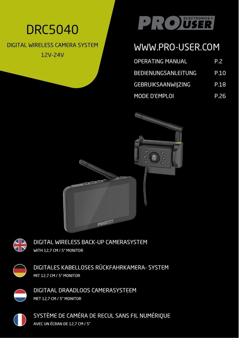
pro user DRC5040 User manual
pro user
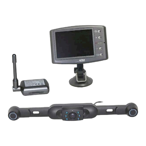
pro user RPC3600 User manual
pro user
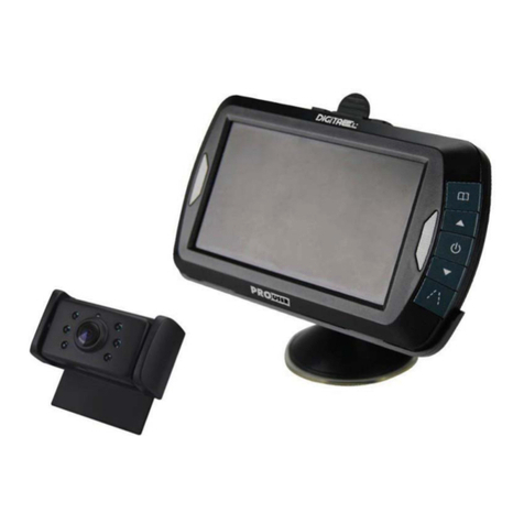
pro user DRC4311 User manual
pro user
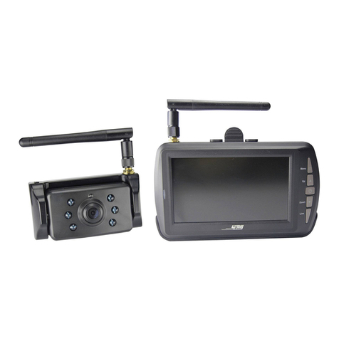
pro user DRC4340 User manual

pro user
pro user RVC3110 User manual
pro user
pro user DRC4310Solar User manual
pro user
pro user APR043 User manual
pro user
pro user DRC7010 User manual
