pro user DRC7010 User manual

* Optional: Extendable with second camera / Erweiterbar um eine zweite Kamera / Uitbreidbaar
met tweede camera / Extensible a deux cameras. Model: DRC-CAM Article Number 20128
DIGITAL WIRELESS BACKUP CAMERA
SYSTEM
DIGITALES KABELLOSES RÜCKFAHR-
KAMERA-SYSTEM
SYSTEME DE CAMERA DE RECUL SANS FIL
NUMERIQUE
DIGITALE DRAADLOOS CAMERASYSTEEM
with 17,8cm / 7” monitor
mit 17,8cm / 7” Monitor
avec écran 17,8cm / 7”
met 17,8cm / 7” monitor
DRC7010
*

2
INTRODUCTION
The Pro-User DRC7010 is a member of the family of advanced car backup systems
manufactured by Pro-User International Ltd. The Pro-User Digital Backup Camera and
Monitor with built in transmitter box will improve your ability to see behind your car,
camper or trailer. We have taken numerous measures in quality control to ensure that
your product arrives in top condition and will perform to your satisfaction.
For optimal performance and safety, please read the following instructions
carefully !
IMPORTANT SAFETY INSTRUCTIONS
If you are not confident working with 12V/24V DC vehicle wiring, removing and
reinstalling interior panels, carpeting, dashboards or other components of your vehicle,
contact the vehicle’s manufacturer, or consider having the camera system professionally
installed.
Interference
By using a digital transmission system, this device is free from interferences coming from
Bluetooth®, cell phones, Wi-Fi routers, power lines and other various electrical equipment.
Maintenance
The camera system is maintenance-free and must not be opened. Any attempt at
modification or repair by the user will entail the loss of your guarantee.
PARTS
1. Monitor and dashboard stand 2. Camera with mounting plate
3. Mounting Accessories 4. Monitor Power Cable
5. Mounting strap (2x) 6. Mounting Plate
and adhesive tape
. Monitor Power Cable

3
INSTALLATION
These instructions are only meant as a general guide due to the number of
different makes & models. For vehicle specific questions contact your vehicle’s
manufacturer.
Camera installation
The camera can be tilted vertically to adjust the viewing angle.Make sure that its field of
view is not obstructed. There are several ways to mount the camera on the back of your
car. But the most convenient is to mount it near the license plate. Supplied is a mounting
plate that can be fixed behind the license plate. The camera itself can fixed on this
mounting plate.
Please note: At some vehicles it may not be possible to mount the camera near the
license plate. You may have to find another spot at the back of your car to mount it.
1. Remove the rear license plate, and then loosen the license plate´s bolts/screws.
2. Position the supplied mounting plate (together with the camera) behind the license
plate bracket. Secure both license plate bracket and mounting plate with the license
plate bracket bolts/screws.

4
3. Reinsert the license plate on the license plate bracket.
4. Choose a routing path for the camera’s power cable through the vehicle’s body to the
backup light circuit.
5. Some vehicles may have a hole available to pass the wire through the trunk, such as
where the license plate light is mounted. Otherwise you probably could drill a hole
close to where the power cable is attached to the camera. Once you have chosen
where the cable will enter the vehicle’s body, remove the camera. If you are able to
use an existing opening, skip the next two steps.
6. Remove the license plate and camera before drilling. ATTENTION: Before drilling
any hole, remove the camera and the licence plate and carefully examine the
area around and behind the installation position. Make sure that there are no
parts that can be damaged (especially electrical cables, components of the
vehicle´s fuel system or any liquid tanks). Please take every reasonable
precaution. Choose a drill that is suitable for the supplied grommet and
material.
7. After drilling the hole, insert the supplied grommet and pass the camera cables
through the grommet into the vehicle.
8. Next you’ll need to find the vehicle’s backup lights. Turn the vehicle’s ignition key to
the accessory position, engage the parking brake and go into reverse. Look at the
vehicle’s tail lights to see where the reverse lights are located (usually the white
lights). To locate the backup light’s 12V/24V (+) wire, it probably will be necessary to
gain access to the rear of the vehicle’s taillight. For help locating the vehicle’s reverse
light circuit contact your vehicle’s manufacturer for vehicle specific wiring diagrams.
9. Once you have located the reverse light circuit you will have to route the camera
cable to that location. Securely fasten the power cable to prevent it from being
caught on any vehicle component such as the trunk hinge. Never route the cable on
the outside of the vehicle!
10. The reverse light sockets on most
vehicles have two wires connected to
them. Usually the negative wire is
black and the positive wire is a colored
wire. If you are uncertain about the
wiring, you can use a 12V/24V
multimeter available at most auto
parts stores, to determine which is the
positive wire. Follow the
manufacturer’s instructions for the
safe use of the multimeter.
11. After determining which wire is the positive and which is the negative, turn off the
ignition key and remove the battery’s negative cable (ground -).

5
12. Connect the camera´s red wire using the supplied in-line wire connectors to the
reverse light’s positive (+) wire. Use a set of slip joint pliers to squeeze them and
insure a good connection.
13. Connect the black wire of the camera´s power cable to the reverse light’s negative (-)
wire or ground.
14. Reinstall the reverse light bulb and the light socket. Secure all the wires with cable
ties or electrical tape.
15. Re-attach the negative battery cable to the battery.
Monitor Installation
When choosing a location for the monitor, make sure the monitor is mounted in
an area that will not obstruct your vision while driving.
The DRC7010 can be fixed in your vehicle in several ways. The monitor can be placed on
your (A) dashboard via the dashboard stand or (B) fixed via the supplied straps on you
visor or a headrest.
A. Dashboard stand *
1. Before mounting the monitor, clean all adherends well. Put one
side of the double-faced adhesive tape on the bottom of the
dashboard stand.
2. Position the stand onto the dashboard
3. Press the stand against the dashboard surface to fix the
location.
4. Snap in the monitor to the stand´s mounting arm.
5. Adjust the mounting arm to suit your viewing angle to the
monitor.
6. In order to remove the monitor, press the arrow sign on the mounting arm to release.

6
* to maximize the bond strength of the adhesive, it is recommended to applicate the
tape under the following conditions:
•All surfaces must be clean, dry, dust and grease free.
•The adherents temperature should be between 21 and 38 degrees Celsius. Don´t
applicate below 10 degrees or under direct sunlight.
•If possible, choose a mounting position where no direct sunlight can heat up the
dashboard stand.
B. Visor and Headrest Mount
1. Use the supplied two straps and pull them through the recesses at the back of the
monitor unit.
2. Position the monitor on the visor or headrest.
3. Pull the straps across the visor or headrest.
4. Fasten the straps.
Monitor 12/24V connection
1. Route the supplied power cable to the vehicle’s cigarette
lighter socket/12V power outlet. The cable routing must not
interfere with the safe operation of the vehicle.
2. Insert the small DC plug of the power cable into the side of the
monitor.
3. Plug in the 12/24 Volt cigarette lighter plug into the vehicle’s
cigarette lighter socket.
Testing the System
1. Check if the vehicle’s negative battery cable (ground) has been reattached.
2. Turn the ignition key to the accessory position - do not start the vehicle.
3. Engage the parking brake, and put the vehicle´s shifter in the reverse position. The
System should activate itself. If not, press the Power-button on the Monitor.
4. If not already done: Please pair your camera(s) to the monitor (as described in
chapter OPERATION)
5. After testing (and re-adjusting if needed) the unit, all cabling should be installed
permanently: Route all wires behind interior panels or under carpeting. Use the
supplied cable ties to keep excess wires neat and compact.
NOTE: UNDER EXTREME BRIGHT LIGHT CONDITIONS, THE SCREEN IMAGE MAY
TAKE A FEW SECONDS TO STABILIZE. PLEASE WAIT UNTIL THE IMAGE HAS
STABILIZED BEFORE BACKING UP.

7
OPERATION
Before the 1st operation: Please pair the monitor to your camera(s) !
(Please refer to the instructions below)
The monitor unit can be paired with a maximum of 2 cameras. Use the
Up/Down buttons in order to switch between the connected cameras or to show
a splitted screen.
General Usage:
Select the desired menu item by using the Up/Down buttons. Then confirm your choice
with the OK button. Press the Menu button to exit a submenu or wait a few seconds
without any input to exit automatically.
Power button
Press the Power button to power-on the monitor. The screen on the monitor will turn on
automatically when the vehicle is in reverse gear (when already paired to the camera(s)
as described below). When the monitor is on and gets a signal, the blue LED will light up,
otherwise it will blink. When the monitor is off, no picture will appear on the screen and
the blue LED will be off.
Menu / Return
Up /Auto Mode
Down / Manual Mode
OK (Confirm)
Lines
Power (On/Off)

8
MENU
Press the Menu button to enter the main menu screen.
PAIRING Menu
Here you can pair up to 2 cameras. Select CAM1 or CAM2 and press the OK button to
start the pairing process.
The device is now ready to pair to the camera (example: CAM1)
Now press the rubber button at the bottom of the camera !

9
Pairing successful.
Back in the PAIRING Menu a symbol appears next to the paired camera CAM1. The unit
will now pair automatically to the camera when powered on. If you have 2 cameras
(optional), please repeat the pairing process as described.
Press the Menu button to exit.
Example: Both cameras have been paired.

10
SETUP Menu
Select the desired sub-menu with the Up/Down buttons and confirm with the OK button.
The respective functions of the sub-menus are being described below.
SETUP-AUTO DISPLAY
This setting allows you to set your main view: The selected camera (CAM1 or CAM2) will
be displayed automatically when backing up. In order to show the picture of both
cameras at the same time, please select SPLIT in the menu (only if both signals can be
received – otherwise the monitor will show the available picture in fullscreen).
SETUP-MIRROR
Select CAM1 or CAM2 in order to mirror the displayed picture horizontally or vertically.

11
SETUP-VERSION
Shows the software-version of the monitor system.
IMPORTANT:
By pressing the Up-button in the VERSION menu for 5 seconds, all cameras will
be un-paired !
PICTURE Menu
After selecting the concerning camera, you can adjust the BRIGHTNESS, CONTRAST or
COLOR of the displayed picture: Choose the desired function with the Up/Down buttons,
confirm by pressing the OK button and change the values with the arrow buttons. Save
the settings with the OK button and exit the screen by pressing the Menu button.
LINES button
This camera system has the option to show guidelines on the
display. This may help you to visually estimate the distances
between objects and your car. By pressing the Lines button,
you can switch this option on and off.
NightVision:
The camera modules have an automatic NightVision infrared function: During night time
or in dark areas the IR LEDs will turn on automatically.
ATTENTION: Protect your eyes ! Do not look directly into the IR LED light.

12
TECHNICAL SPECIFICATIONS
Camera
Operating Voltage
8-30V DC
Operating Current
<120mA(IRLED OFF); <170mA(IRLED ON);
Sensor Type
CMOS
Resolution
800x480
Optical lens
F1.7mm / F2.0
Transmission frequency
2.4 GHz (ISM band)
RF transmission distance
up to 100 meters (open area)
LCD monitor
Operating Voltage
8-30V DC
Standby Current !
30mA
Operating Current
!300mA
LCD Screen Size
17,8cm / 7 inch
Resolution
800x480
Environmental Temperature
-10 to +45 degree Celsius
This model may be operated in EU countries.
ENVIRONMENTAL PROTECTION
The product is classed as Electrical or Electronic Equipment and should not
be disposed of with other household or commercial waste at the end of its
working life. Please recycle where facilities exist. Ask your local authority or
retailer for recycling advice.
WARRANTY
Pro-User warrants this product for a period of 2 years from the date of purchase to the
original purchaser. Warranty is not transferable. Warranty covers defect against
workmanship and materials only. To obtain warranty service, please return the unit to
the place of purchase or authorized Pro-User dealer together with your proof of purchase.
The warranty is void if the product has been damaged or not used as described in this
manual. Warranty is void if a non-authorized repair has been performed. Pro-User makes
no other warranty expressed or implied. Pro-User is only responsible for repair or
replacement (at Pro-Users’ Discretion) of the defective product and is not responsible for
any consequential damage or inconvenience caused by the defect.

13
EINLEITUNG
Das Pro-User DRC7010 gehört zur Familie der zukunftsweisenden Auto-RückfahrKamera-
Systeme der Firma Pro-User International Ltd. Die digitale kabellose Pro-User
Rückfahrkamera mit Monitor ermöglicht es Ihnen, hinter Ihr Auto, Wohnmobil, oder
Anhänger zu sehen. Permanente Qualitätskontrolle stellt sicher, dass Sie ein
hochwertiges Produkt erhalten, dass Ihnen hohe Zuverlässigkeit und Funktionalität bietet.
Bitte lesen Sie die Bedienungs- und Montageanleitung sorgfältig durch und
befolgen Sie insbesondere die Sicherheitshinweise.
WICHTIGE SICHERHEITSHINWEISE
Falls Sie sich nicht zutrauen dieses System selbständig zu installieren oder Sie nicht
vertraut sind mit den notwendigen Arbeiten an Ihrem Kraftfahrzeug (evtl. Bohren von
Löchern, Abnehmen von Verkleidungen, Verlegen von Kabeln, elektrischer Anschluss
etc.), kontaktieren Sie Ihr Autohaus oder die Kfz-Werkstatt Ihres Vertrauens, um dort
eine professionelle Montage des Systems zu beauftragen.
Störungen durch Funk
Durch die fortschrittliche digitale Übertragungstechnik bleibt dieses Kamera System
weitgehend unbeeinflusst von Störungen, welche von z.B. WiFi- und Bluetooth®-Geräten,
Mobiltelefonen oder Hochspannungsleitungen ausgehen könnten.
Wartung und Reparatur
Dieses Kamera-System ist wartungsfrei und darf nicht geöffnet werden! Sämtliche
Modifikations- oder Reparaturversuche haben ein Erlöschen der Garantie zur Folge.
LIEFERUMFANG
1. Monitor mit Standfuß 2. Kameramodul mit Montageplatte
3. Installations-Material 4. Stromkabel für den Monitor
5. Montagebänder (2x) 6. Befestigungsplatte
und Klebefläche für den Standfuß

14
MONTAGE
Aufgrund der Vielzahl an Fahrzeugtypen bitten wir Sie die nachfolgende
Montageanleitung lediglich als generellen Leitfaden anzusehen. Bei fahrzeug-
spezifischen Fragen wenden Sie sich bitte an Ihren Fahrzeughersteller.
Montage der Kamera
Die Kamera ist vertikal schwenkbar, um den Bildausschnitt gegebenenfalls anpassen zu
können. Vermeiden Sie bei der Auswahl der Montageposition eine Einschränkung des
Sichtfelds der Kamera. Es gibt verschiedene Möglichkeiten, die Kamera am Heck Ihres
Fahrzeuges zu befestigen. Nachfolgend beschreiben wir Ihnen beispielhaft die Montage
der Kamera in der Nähe Ihres Kennzeichens, da diese Position sich häufig als geeignet
erwiesen hat. Die mitgelieferte Montageplatte wird dabei hinter dem Nummernschild
befestigt und auf dieser Montageplatte dann die Kamera selbst.
Bitte Beachten: Bei manchen Fahrzeugen ist es leider nicht möglich, die Kamera nahe
dem Nummernschild zu befestigen. In diesem Fall müssen Sie einen anderen Montageort
auswählen.
1. Nehmen Sie das Nummernschild aus der Halterung, lösen Sie danach die Schrauben
des Nummernschildhalters und nehmen Sie diesen ab.
2. Richten Sie die Befestigungsplatte (mit der Kamera) hinter dem Nummernschildhalter
aus und montieren Sie die Befestigungsplatte und den Nummernschildhalter wieder
am Fahrzeug.

15
3. Befestigen Sie nun Ihr Nummernschild wieder auf dem Nummernschildhalter.
4. Suchen Sie nun eine Möglichkeit, das Anschlußkabel der Kamera durch die Karosserie
Ihres Autos zur Stromzuleitung des Rückfahrlichtes zu führen.
5. Einige Fahrzeuge haben in der Nähe des Kennzeichens eine Kabeldurchführung, durch
welche Sie das Kabel durchziehen können. Falls das bei Ihnen nicht der Fall ist,
müssen Sie in der Nähe des Kennzeichens, bevorzugt dicht an der Stelle, wo sich das
Kabel der Kamera befindet, selbst eine Durchführung bohren. Wenn Sie eine
geeignete Stelle für die Durchführung gefunden haben, können Sie die Kamera und
das Kennzeichen wieder demontieren. Falls Sie eine vorhandene Öffnung benutzen,
können Sie die zwei folgenden Schritte überspringen.
6. Bohren der Kabeldurchführung: ACHTUNG: Bevor Sie bohren, demontieren Sie
die Kamera und das Nummernschild und prüfen Sie sorgfältig, was sich
hinter der von Ihnen gewählten Bohrposition befindet. Prüfen Sie
insbesondere, dass sich dort keine Elektrokabel, Flüssigkeitstanks oder
andere Leitungen befinden. Beachten Sie diesbezügliche alle notwendigen
Vorsichtsmaßnahmen! Wählen Sie einen für die mitgelieferte Kabeltülle und
das Material geeigneten Bohrer.
7. Nachdem Sie gebohrt haben, befestigen Sie die mitgelieferte Kabeltülle als
Kantenschutz in der Bohrung, um das Kabel vor den scharfkantigen Rändern des
Bohrloches zu schützen. Dann ziehen Sie das Kabel der Kamera ins Fahrzeuginnere.
8. Als nächstes müssen Sie die Spannungsversorgung einer Ihrer Rückfahrleuchten
finden. Stellen Sie die Zündung Ihres Auto in die Zubehörposition (nicht starten!),
ziehen Sie die Handbremse an und legen Sie den Rückwärtsgang ein. Am Heck Ihres
Fahrzeugs sollten jetzt die weißen Rückfahrleuchten in Betrieb sein. Um die Kabel
vom Rückfahrscheinwerfer zu finden, müssen Sie ggf. die Rückseite Ihrer
Heckbeleuchtung öffnen und die entsprechenden Kabel orten. Falls Sie Probleme mit
diesem Schritt haben, fragen Sie hierzu Ihr Autohaus oder die Kfz-Werkstatt Ihres
Vertrauens.
9. Wenn Sie die entsprechenden Leitungen gefunden haben, verlegen Sie das Kabel der
Kamera zu diesem Punkt hin. Stellen Sie sicher, dass nach der Verlegung des Kabels
die Heckklappe betätigt werden kann, ohne dass das Kabel scheuert. Verlegen Sie
das Kabel auf keinen Fall außerhalb des Autos!
10. Am Sockel der Rückfahrleuchte sind in
der Regel zwei Drähte befestigt.
Meistens ist die negative Zuleitung
schwarz (GROUND) und die positive
Zuleitung farbig (+12/24V). Prüfen
Sie im Zweifel die Polarität der
Leitungen mit einem geeigneten
Multimeter (im Fachhandel erhältlich).
Beachten Sie die Bedienungsanleitung
Ihres Multimeters für dessen
bestimmungsgemäßen Gebrauch.

16
11. Wenn Sie die Polarität der Zuleitungen festgestellt haben, schalten Sie die Zündung
aus und entfernen Sie das Massekabel (Minuspol) Ihrer Autobatterie, um
sicherzustellen, dass kein Stromfluß stattfinden kann.
12. Verbinden Sie den roten Draht des Kamera-Anschlußkabels mit der positiven Leitung
des Rückfahrscheinwerfers. Benutzen Sie hierzu die beiliegenden Kabelklemmen.
Drücken Sie die Klemmen fest mit einer Zange zusammen und stülpen Sie die
Plastikabdeckung über die Kontaktstelle.
13. Verbinden Sie nun den schwarzen Draht des Kamera-Anschlußkabels auf die gleiche
Weise mit der negativen (Masse-)Leitung des Rückfahrscheinwerfers.
14. Achten Sie darauf, dass alle Leuchtmittel wieder eingesetzt wurden und befestigen
Sie etwaig entfernte Abdeckungen der Heckleuchte. Benutzen Sie ggf. Kabelbinder
und Isolierband, um alle Kabel sicher und fest zu verlegen!
15. Schließen Sie das Massekabel (Minuspol) Ihrer Autobatterie wieder an.
Montage des Monitors
Wählen Sie den Installationsort Ihres Monitors so aus, dass während der Fahrt
die Sicht nicht behindert wird
Der Monitor des DRC7010 kann auf verschiedene Weise installiert werden: Er kann z.B.
mittels Standfuß auf Ihrem Armaturenbrett befestigt werden (Variante A) oder auch mit
Hilfe der beiliegenden Montagebänder an der Sonnenblende oder an einer Kopfstütze
(Variante B) fixiert werden.
A. Befestigung mittels Standfuß *
1. Reinigen Sie vor der Montage die Klebefläche des Standfußes
gründlich und kleben Sie das doppelseitige Klebeband auf
dessen Rückseite

17
2. Positionieren Sie Standfuß an der gewünschten Position
3. Drücken Sie die Klebeflächen fest aufeinander
4. Schieben Sie den Monitor auf die Standfußhalterung
5. Richten Sie den Bildschirm auf die von Ihnen gewünschte Position aus und fixieren Sie
die Position
6. Um den Monitor vom Standfuß zu entfernen, müssen Sie auf dessen Rückseite die
Pfeiltaste (siehe Bild) betätigen, um die Rastung zu lösen.
* Um eine hohe Klebekraft des doppelseitigen Klebebandes zu gewährleisten, empfielt
es sich die folgenden Verklebe-Empfehlungen einzuhalten:
•Die Klebeflächen müssen sauber, staub- und fettfrei sein.
•Die Temperatur der Klebeflächen sollte zwischen 21 und 38 Grad Celsius liegen.
Eine Verklebung unter 10 Grad Celsius sollte vermieden werden, wie auch direkte
Sonneneinstrahlung
•Der Montageort sollte nach Möglichkeit so gewählt werden, dass keine direkte
Sonneneinstrahlung den Montagefuß aufheizen kann.
A. Befestigung an der Sonnenblende oder der Kopfstütze
1. Fädeln Sie die beiden mitgelieferten Montagebänder durch die Ösen auf der
Rückseite des Monitors und über die Sonnenblende bzw. Kopfstütze.
2. Richten Sie den Monitor in der gewünschten Lage aus
3. Straffen Sie die Montagebänder
Anschluss des Monitors an das Bordnetz des Fahrzeugs
1. Verlegen Sie das mitglieferte Anschlußkabel vom Monitor zur
Bordspannungs-steckdose (Zigarettenanzünder) Ihres
Fahrzeugs. Achten Sie darauf, dass Sie die Kabelführung so
gestalten, dass Sie das Anschlusskabel beim Führen des
Fahrzeugs nicht beeinträchtigt.
2. Stecken Sie den Gleichspannungsstecker (Hohlstecker) seitlich
in den Monitor (siehe Bild)
3. Stecken Sie den 12V/24V Zigarettenanzünder-Adapter in die
Bordspannungssteckdose.
System Test
1. Prüfen Sie, ob Sie das Massekabel der Autobatterie wieder befestigt haben.
2. Schalten Sie die Zündung Ihres Autos in die Zubehörposition (Das Fahrzeug nicht
starten)
3. Ziehen Sie die Handbremse an und legen Sie den Rückwärtsgang ein. Das
Rückfahrsystem sollte sich jetzt aktivieren. Falls nicht, drücken Sie bitte die Power-
Taste.
4. Falls noch nicht geschehen, koppeln Sie die Kamera mit dem Monitor, wie es im
Kapitel BEDIENUNG beschrieben wird und führen Sie evtl. notwendige Einstellungen
durch (z.B. Spiegeln des Kamerabilds).
5. Nachdem Sie das Gerät auf Funktion überprüft haben und falls notwendig feinjustiert
haben, sollten Sie alle noch frei liegenden Kabel unterbringen: Verstauen Sie die
Verkabelung hinter Fahrzeugverkleidungen oder unter dem Fahrzeugteppich, so dass
sie nicht mehr sichtbar ist. Benutzen Sie gegebenenfalls die beiliegenden Kabelbinder,
um Überlängen der Kabel zu bündeln.
HINWEIS: BEI SEHR HELLEN LICHTVERHÄLTNISSEN BENÖTIGT DER MONITOR
EINIGE SEKUNDEN UM SICH ANZUPASSEN. BITTE WARTEN SIE BIS SICH DAS
BILD STABILISIERT HAT BEVOR SIE RÜCKWÄRTSFAHREN.

18

19
BEDIENUNG
Hinweis: Bitte koppeln Sie die Kamera mit dem Monitor vor der ersten
Verwendung wie unten beschrieben.
Die Monitoreinheit kann mit bis zu 2 Kameras verbunden werden. Benutzen Sie
die Pfeiltasten, um zwischen den angeschlossenen Kameras zu wechslen bzw.
um einen geteilten Bildschirm mit beiden Kamerabildern anzuzeigen.
Allgemein
Drücken Sie die Menü-Taste, um das Menü zu aktivieren bzw. eine Menüebene
zurückzuspringen. Wählen Sie mit den Pfeiltasten den gewünschten Menüpunkt aus und
Bestätigen sie die Wahl mit der OK-Taste. Nach einigen Sekunden ohne Eingabe wird das
Menü automatisch verlassen.
Power Schalter
Drücken Sie die Power-Taste um den Monitor ein- oder auszuschalten. Das Bild auf dem
Monitor erscheint automatisch, wenn der Rückwärtsgang eingelegt wird (vorausgesetzt
die Kamera(s) wurden wie unten beschrieben bereits gekoppelt). Wenn ein Bild erscheint,
leuchtet eine blaue LED am Gehäuserand auf. Wenn der Monitor betriebsbereit ist, aber
kein Bild empfangen wird, blinkt die blaue LED. Ist der Monitor ausgeschaltet, wird kein
Bild angezeigt und die blaue LED bleibt aus.
Menü / Zurück
Pfeiltaste (Auto)
Pfeiltaste (Manuell)
OK
Hilfslinien-Taste
Power-Taste

20
MENÜ
Drücken Sie die Menü-Taste, um das Hauptmenü aufzurufen.
PAIRING Menü (Kopplung der Kameras)
Im PAIRING-Menü können Sie die Ankopplung von bis zu 2 Kameras vornehmen: Wählen
Sie CAM1 oder CAM2 mit den Pfeiltasten aus und bestätigen Sie mit der OK-Taste, um
mit der Kopplung zu beginnen.
Der Monitor ist nun zur Ankopplung (hier im Beispiel: Kamera 1) bereit.
Drücken Sie nun die schwarze Gummi-Taste auf der Rückseite der
Kameraeinheit, um die Kopplung durchzuführen.
Table of contents
Languages:
Other pro user Digital Camera manuals
pro user
pro user RVC3110 User manual
pro user
pro user APR043 User manual
pro user
pro user RPC3600 User manual
pro user
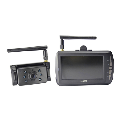
pro user DRC4340 User manual
pro user
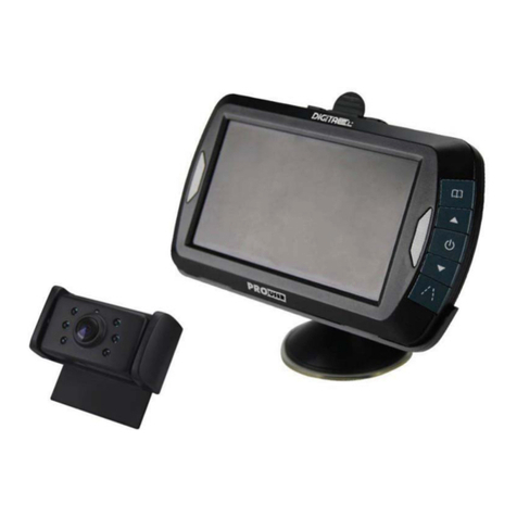
pro user DRC4311 User manual
pro user
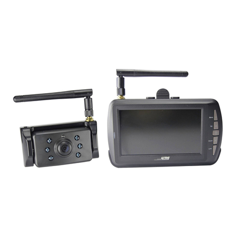
pro user DRC4340 User manual
pro user
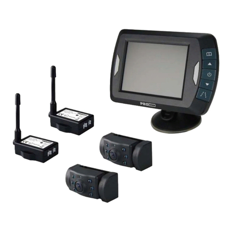
pro user APR035X2 User manual
pro user
pro user DRC5040 User manual
pro user
pro user DRC4310Solar User manual
pro user
pro user APR043DC User manual


