PROALL Mobile Mixer User manual

pg. 1
Operator’s Manual, Ranger Gunite r1.0
ProAll
Mobile Mixer
Operator’s Manual
RANGER GUNITE
MX05000
February 2021
Rev 1.0

pg. 2
Operator’s Manual, Ranger Gunite r1.0
5810 - 47 Avenue, Olds, Alberta, Canada, T4H 1V1
Einfo@proallinc.com | P403-335-9500 | F403-335-9560

pg. 3
Operator’s Manual, Ranger Gunite r1.0
Contents
1. RANGER GUNITE ............................................................................................4
1.01 OPERATION ............................................................................................4
1.02 HOME SCREEN........................................................................................5
1.03 MENU.....................................................................................................6
1.04 MIX ENTRY..............................................................................................7
1.05 MIX SELECT.............................................................................................8
1.05.1 MAIN SCREEN..................................................................................8
1.05.2 CUSTOMER INFORMATION.............................................................9
1.05.3 VOLUME STOP...............................................................................10
1.06 TOTALS .................................................................................................11
1.07 DIGITAL READOUTS..............................................................................12
1.08 MIXER CONTROL ..................................................................................13
1.09 JOB LOG................................................................................................15
1.09 DISPLAY SETTINGS................................................................................16
1.09.1 PRINTER SETTINGS ........................................................................17
1.10 DIAGNOSTICS .......................................................................................18
1.11 ALARM LOG..........................................................................................19
1.12 MIXER CALIBRATION ............................................................................20
1.12.1 POWDER CALIBRATION.................................................................21
1.12.1.1 POWDER CALIBRATION RESET AND TRIALS...........................23
1.12.2 GATES CALIBRATION .....................................................................24
1.12.2.1 GATE CURVE SLOPE................................................................26
1.12.2.2 GATES CALIBRATION RESET AND TRIALS ...............................27
1.13 MIXER SETTINGS ..................................................................................28
1.13.1 CONTROL SETTINGS ......................................................................29
1.13.1.1 MIXER OPTIONS .....................................................................31
1.13.2 FILE COPY ......................................................................................32
1.13.3 COMPANY INFORMATION ............................................................33
1.14 ALARM SYMBOLS & TROUBLESHOOTING............................................34

pg. 4
Operator’s Manual, Ranger Gunite r1.0
1. RANGER GUNITE
1.01 OPERATION
1. The display is fully touch-sensitive; there are no physical buttons to be pressed.
Some screens will have on-screen buttons to be tapped and certain fields can be activated for input, which will prompt a
keypad for data entry.
Keypads are associated with various fields on the display and allow the user to quickly enter a string or numeric values.
1. String Keypad 2. Numeric Keypad
1

pg. 5
Operator’s Manual, Ranger Gunite r1.0
1.02 HOME SCREEN
1. Auger speed percentage.The auger speed is adjustable from 0-100%. Speed setting is dependant on the
materials used and the production rates required. For gunite, this is typically set around 60-80%.
2. With gate height verification sensor:
The center number is the actual gate height position.
The small number in blue is the mix design gate position required.
Without gate height verification sensor:
The large number is the mix design gate position.
3. Belt speed percentage. The belt speed is adjustable from 0-100%. Speed setting is dependant on the gunite pump
production rate required.
4. MENU screen button. Pressing this will take the user to the main menu navigation screen.
5. Cement meter auger RPM. This gauge is used for reference to ensure the cement auger is on and turning.
6. Production rate/belt RPM gauge. Used to verify production speeds and belt RPM settings.
7. Hydraulic oil pressure. This is a reference for the load mixer and can be used for diagnostic purposes.
8. Selected mix design number. The mix number of the selected design on the Mix Select screen.
9. Total concrete volume currently produced.
10. Selected mix design strength.
1
2
3
4
5
6
7
8
9
10

pg. 6
Operator’s Manual, Ranger Gunite r1.0
1.03 MENU
1. Mix designs are loaded and entered here.
2. Customer required mix design is selected here.
3. Current mix totals before reset.
4. Redundant mixer controls, over-rides and function selections can be found here.
5. The last 25 jobs are stored here. They can be viewed or re-printed.
6. Current date and time.
7. Lifetime production since in operation. Total is updated after reset.
8. Total hours the belt has run.
9. Set date and time, units, print data selection and display brightness can be found here.
10. Calibration data for powders and aggregates are entered here.
11. Configuration values for the mixer are entered here.
12. Digital Readouts. Digital display of mix process values such as counts and rpm.
13. Hydraulic and electrical diagnostics can be viewed here along with an alarm log, for troubleshooting purposes.
14. Home shortcut. Return to the Home screen.
1
2
3
4
5
6
7
8
9
10
11
12
13

pg. 7
Operator’s Manual, Ranger Gunite r1.0
1.04 MIX ENTRY
1. Use the arrows to navigate through the different mix designs database.
2. Load button. Mix designs can be loaded from a USB stick. The mix design file is a specially formatted CSV file. This
file can be loaded from a previous back or edited in Excel and loaded back in.
3. Menu shortcut. Return to the main menu.
4. Home shortcut. Return to the home screen.
5. Calculate button. The display can calculate the gate setting value and the total counts required. These values are
calculated depending on the aggregate and powder materials selected in the calibration screens.
6. Save button. It saves the current mix design.
7. Mix design number. The mix entry menu can hold up to 50 mix designs. Select the mix number by navigating using
the up and down arrows.
8. Define a name for your mix design.
9. Belt counts can be auto-calculated or manually entered if calculated elsewhere.
10. Gate position can be auto-calculated or manually entered if calculated elsewhere.
11. Sand weight required for the mix design.
12. Cement weight required for the mix design.
13. Aux weight required for the mix design. Aux is an optional powder feeder.
14. Mix design strength.
15. Fibre weight required for the mix design, if equipped.
16. Cement set is always 100% unless optional lean valving installed. Lean setting dependant on the valve installed,
but typically 50%.
17. Aux set is the auxiliary powder feeder setting relative to the belt.
1
2
3
4
5
6
7
8
9
10
11
12
13
14
15
16
17

pg. 8
Operator’s Manual, Ranger Gunite r1.0
1.05 MIX SELECT
1.05.1 MAIN SCREEN
1. Use the arrows to navigate through the different mix designs database.
2. Customer and job information enter a pop-up window. See page 9.
3. Volume stop entry pop-up window. See page 10.
4. Menu shortcut. Return to the main menu.
5. Home shortcut. Return to the home screen.
6. Customer required mix design is selected here.
7. Calculated max production rate based on the maximum belt speed setting.
1
2
3
4
5
6
7
pg. 9
Operator’s Manual, Ranger Gunite r1.0
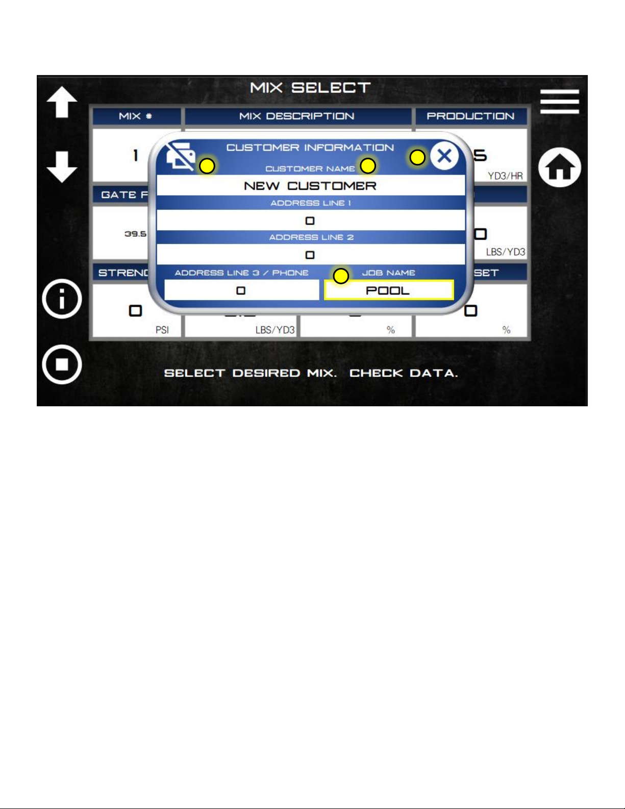
1.05.2 CUSTOMER INFORMATION
1. Close pop-up when selection is complete.
2. Select if the customer information is to be printed on the job ticket or not.
3. Enter customer information here. This data would be printed on the ticket if this print option is active.
4. A specific job name can be entered here. This job name is printed on the job ticket and stored in the mix/job log.
1
2
4
3
pg. 10
Operator’s Manual, Ranger Gunite r1.0
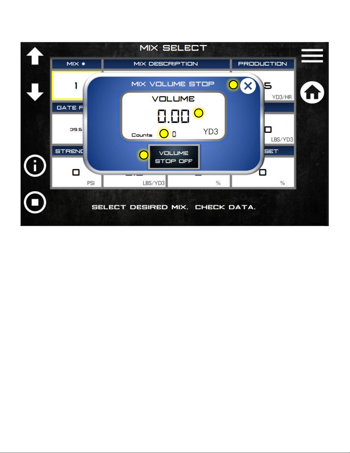
1.05.3 VOLUME STOP
1. Close pop-up when selection is complete.
2. The total volume mixed before the belt will automatically stop.
3. The total belt count before the belt stops.
4. Button to activate the volume stop function.
1
2
4
3
pg. 11
Operator’s Manual, Ranger Gunite r1.0
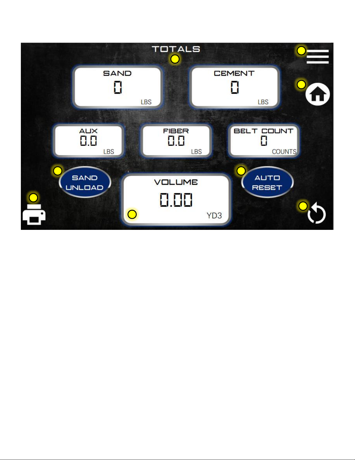
1.06 TOTALS
1. Print a ticket by touching this button.
2. Menu shortcut. Return to the main menu.
3. Home shortcut. Return to the home screen.
4. Reset totals by touching this button. A reset acknowledgment screen will appear. The operator must select “yes”
to finish the reset of totals and log the job to the memory.
5. Totals are calculated using values from the mix design database and belt counts.
6. Press this button if Sand is to be unloaded without cement. The cement total will not calculate, but it will log an
aggregate unload event in the mix log.
7. Auto reset ON will activate the totals reset page after the ticket print has been completed. The reset screen will
still appear if a reset is not desired and “no”can be selected to skip the reset.
8. Total volume produced before a reset. This value is the same on the home screen.
1
2
3
4
5
6
7
8
pg. 12
Operator’s Manual, Ranger Gunite r1.0
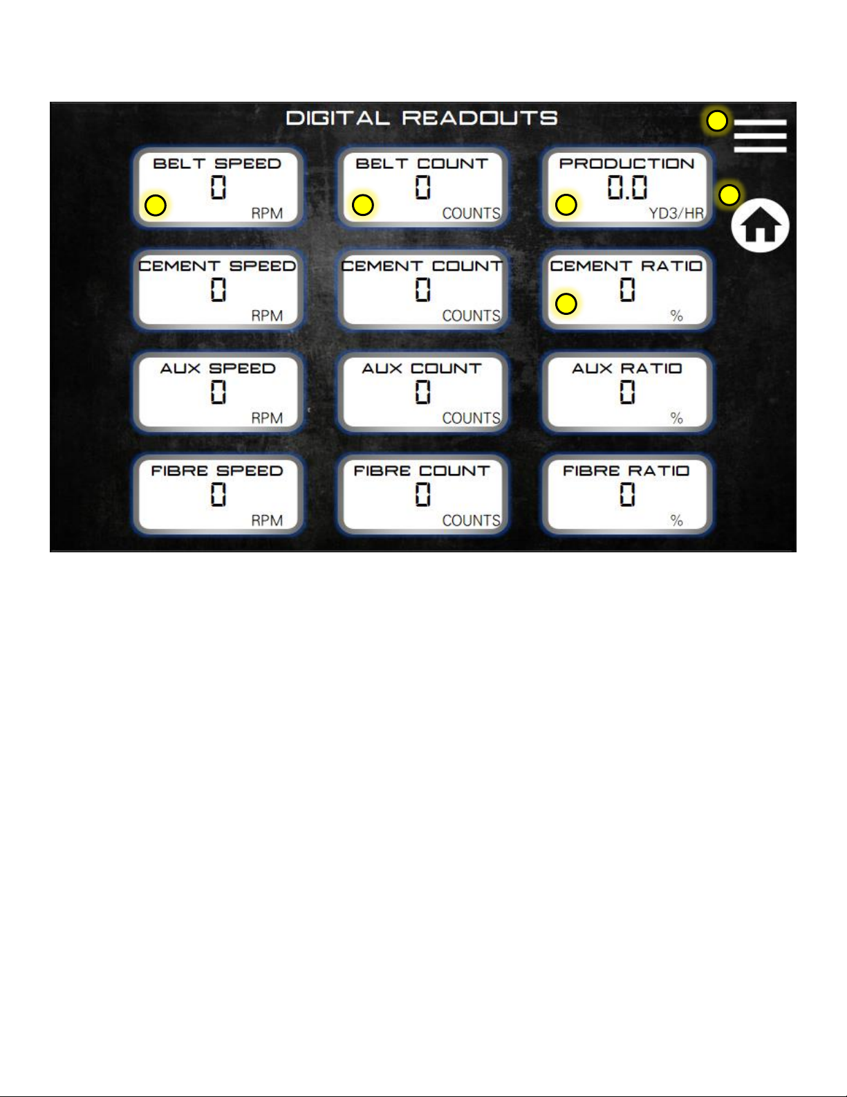
1.07 DIGITAL READOUTS
1. Menu shortcut. Return to the main menu.
2. Home shortcut. Return to the home screen.
3. This column of values is the various functions RPM readings.
4. This column is used for calibration and diagnostics purposes. Belt counts used in volume calculation.
5. Running production rate.
6. Ratio is the difference in belt speed versus cement/aux and fibre speed.
1
2
3
4
5
6

pg. 13
Operator’s Manual, Ranger Gunite r1.0
1.08 MIXER CONTROL
1. Menu shortcut. Return to the main menu.
2. Home shortcut. Return to the home screen.
3. Auto vibrator set-up times are adjusted here. Total on-time in seconds for each vibrator can be set. VIB1-SAND
Front, VIB2-SAND Back, VIB3-Cement and VIB4-Aux
4. VIB gap time is the delay between each vibrator ON sequence.
5. Momentary Boom Up and Down.
6. Momentary Auger Forward and Auger Reverse.
7. High engine idle trigger.
8. Latched Auger Mix (Latching is done on ECU)
9. Belt / Mix Start.
10. Cement / Aux Unload. Bypasses the belt drive circuit to unload powders only.
11. Momentary Belt Forward.
12. Manually turn oil cooler ON. Typically used to verify oil cooler operation.
13. Manually run chain oiler when belt running. It does not wait for the total belt revolutions cycle to start the
sequence. It will automatically shut-off after 60 seconds of continuous belt operation.
14. Manually run mix auger grease system.
15. Fault reset is a momentary button used to reset/clear any alarms on the display.
16. Level over-ride function. This will over-ride any low-level sensors like cement low or gate material in case of
malfunction or to finish a job.
17. Gates over-ride function. This will allow the operator to temporarily over-ride the gate height sensors. If left on
the belt counts are recorded in the log from start to finish of height over-ride.
1
2
3
4
5
6
7
8
9
10
11
12
13
14
15
16
17
77
18
19

pg. 14
Operator’s Manual, Ranger Gunite r1.0
18. Press Vib select button to activate the vibrator autoselect mode. If this button is activated the operator can press
any of the required vibrators on the keypad to be in auto mode. The keypad vibrator button amber LED will come
on to indicate the vibrator is in auto sequence. Once the required vibrators are selected, press Vib select again to
turn off selection mode.
19. Vib auto will run the automatic vibrator sequence even if the belt/mixer isn’t running.

pg. 15
Operator’s Manual, Ranger Gunite r1.0
1.09 JOB LOG
1. Menu shortcut. Return to the main menu.
2. Home shortcut. Return to the home screen.
3. Selected job log number. Max number of jobs in the log is 25. After 25 the log writes over the first and
subsequent jobs.
4. Print currently selected job.
5. Reset job numbers to start at 1.
6. Mix log data total. The mix log is independent of the job log and stores all jobs completed or reset by the mixer
operator. This data is not viewable on the display but can be copied to a USB stick for review in Excel.
7. Index the job log up or down using the arrow keys.
1
2
3
4
5
6
7

pg. 16
Operator’s Manual, Ranger Gunite r1.0
1.09 DISPLAY SETTINGS
1. Menu shortcut. Return to the main menu.
2. Home shortcut. Return to the home screen.
3. Display backlighting adjustment percentages can be viewed on the bar graph.
4. Display backlighting UP or DOWN.
5. Units selection. Volume and weight units are shown in blue along with the units system selected. The units are
selected on the US and Metric units keys.
6. Production rate gauges. All gauges on the HOME screen can be changed to show the actual production rate per
hour or unit volume.
7. Rate per minute gauges. All gauges on the HOME screen can be changed to show actual revolutions per minute.
8. Time and date setting. Touch the mm/dd/yy to select dd/mm/yy if desired.
9. Printer settings pop-up. Select what you want to print on a job ticket. See page 17.
1
2
3
4
5
6
7
8
9
pg. 17
Operator’s Manual, Ranger Gunite r1.0
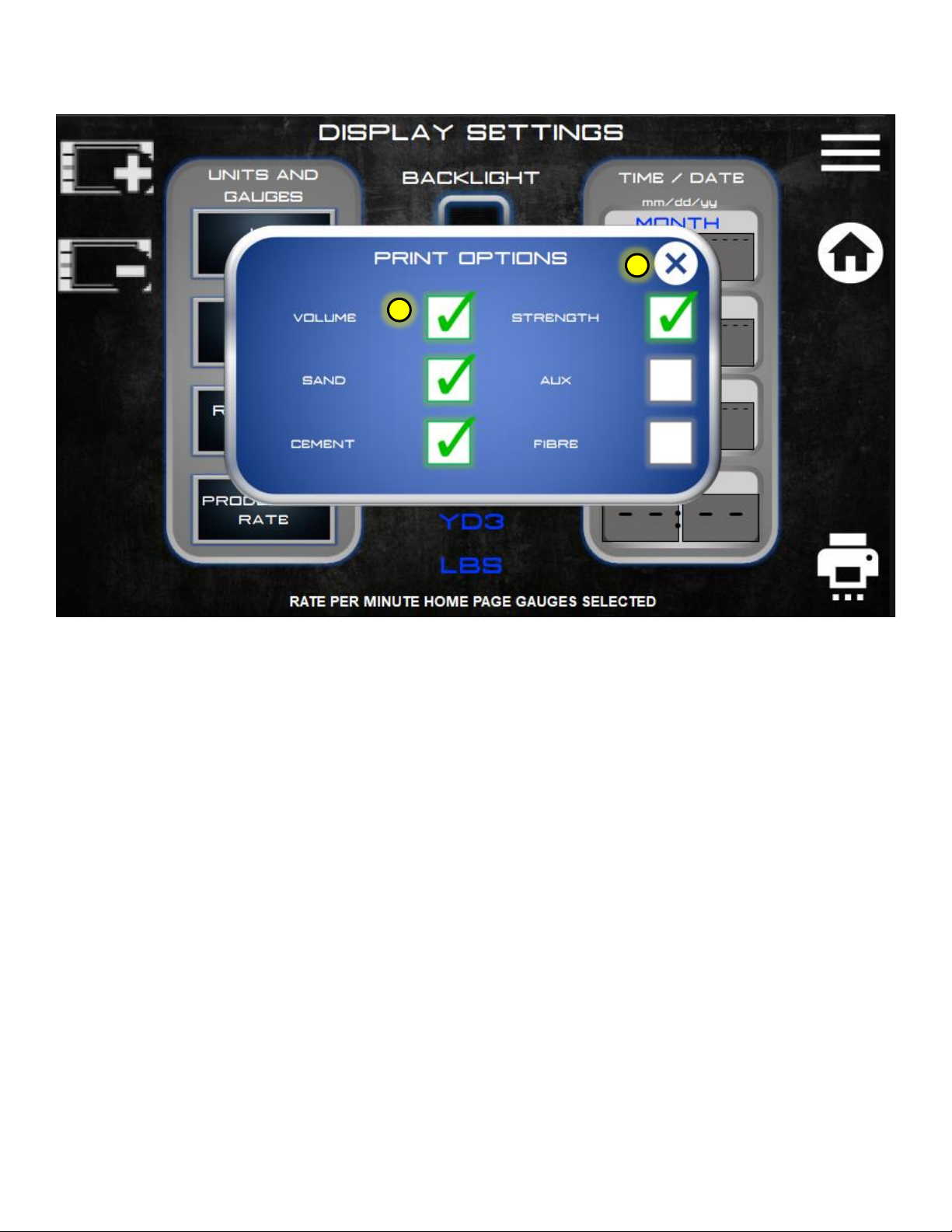
1.09.1 PRINTER SETTINGS
1. Close pop-up when selection is complete.
2. Select the desired items to print on a job ticket if mixer equipped with printer.
1
2

pg. 18
Operator’s Manual, Ranger Gunite r1.0
1.10 DIAGNOSTICS
1. Menu shortcut. Return to the main menu.
2. Home shortcut. Return to the home screen.
3. Hydraulic pressure. Shows current outlet pressure on the main pump. Also shows auxiliary pump pressure if
equipped with hydraulic gunite pump outputs.
4. Oil temperature. Shows current hydraulic oil temperature.
5. Oil temperature units can be changed here.
6. Hydraulic pressure units can be changed here.
7. Alarm log. Screen showing the history of alarms. See page 19.
8. CANBUS and input device diagnostics. Any device on the CANBUS communication network is monitored to ensure
it is sending data to the computer. If the indicator is red then the device either does not exist (optional component)
or there is a fault/disconnect somewhere in the system.
9. CAN Reset is used to initialize or reset the CAN devices' communication parameters. Typically used when installing
a new device.
10. Voltage at the input pin of ECU/computer.
11. Individual electrical device current draw can be checked here. Touch the name in blue and use the up/down touch
keys to select a device to monitor. The current draw is in milliamps.
1
2
4
3
7
5
6
10
11
9
8
pg. 19
Operator’s Manual, Ranger Gunite r1.0
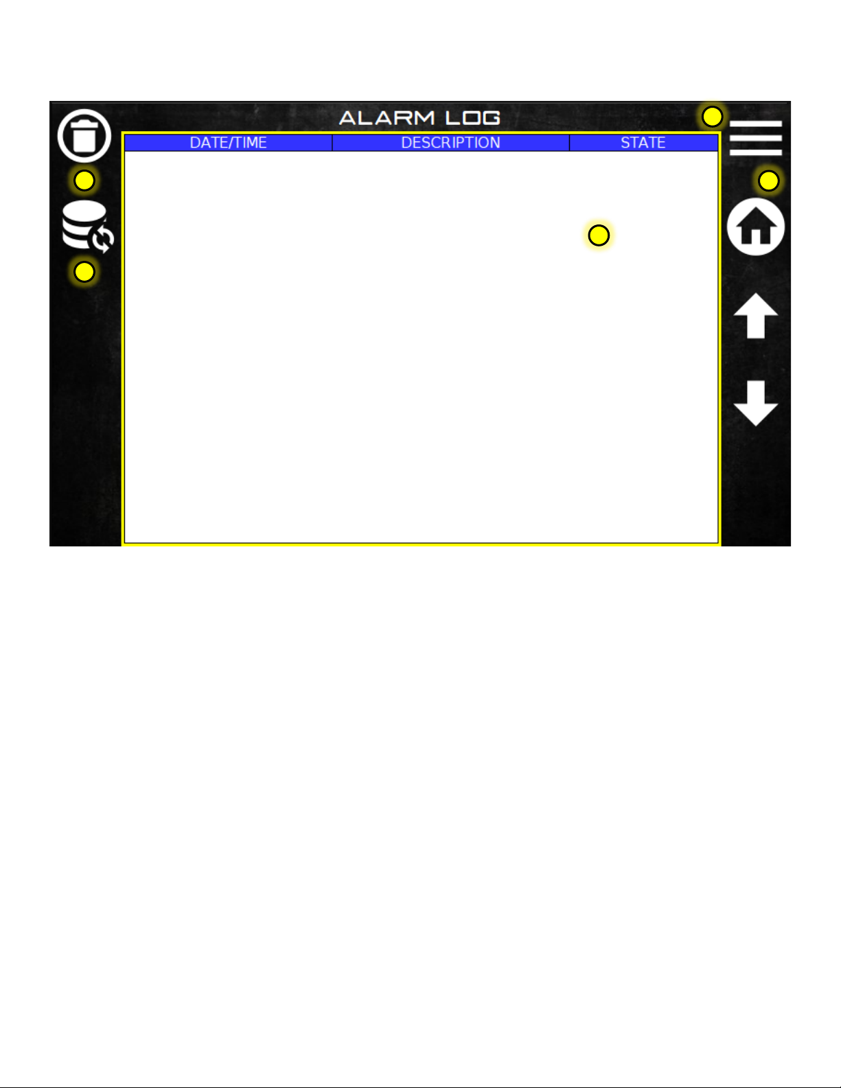
1.11 ALARM LOG
1. Menu shortcut. Return to the main menu.
2. Home shortcut. Return to the home screen.
3. Alarm log table. The table will store up to 100 alarm points. After 100 it writes over the first alarm and continues
writing over previous alarms. To scroll through the alarm log, touch the log table. The border will turn green. Use
the up/down arrow keys to scroll through the table.
4. The alarm log can be deleted and started new by pressing DELETE.
5. The alarm log can be refreshed if alarms are occurring while in the alarm log screen. The log is automatically
refreshed when the alarm log is selected from the diagnostics screen.
1
3
4
2
3
pg. 20
Operator’s Manual, Ranger Gunite r1.0
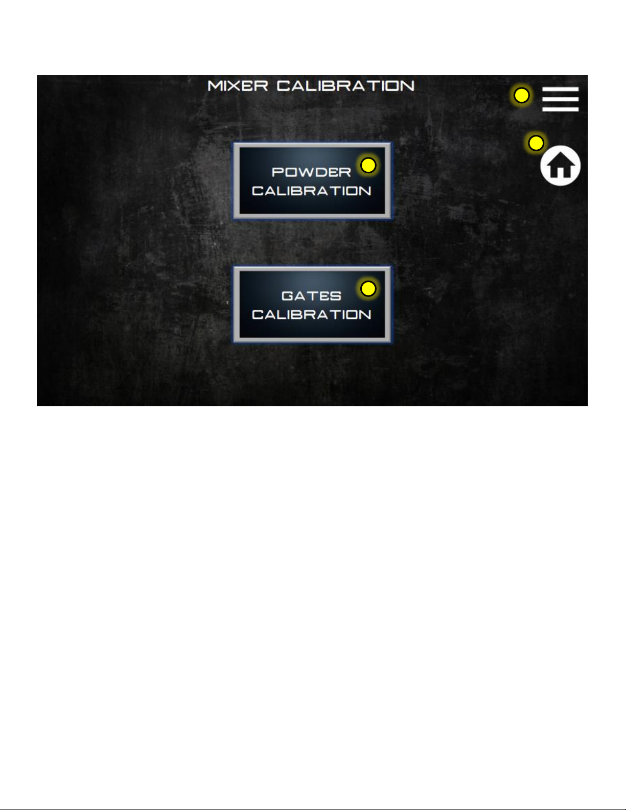
1.12 MIXER CALIBRATION
1. Menu shortcut. Return to the main menu.
2. Home shortcut. Return to the home screen.
3. Press the button to go to the powder calibration screen. Cement, Aux, and Fibre are calibrated here.
4. Press the button to go to the gates calibration screen. Sand is calibrated here.
1
2
3
4
Table of contents
Other PROALL Mixer manuals


