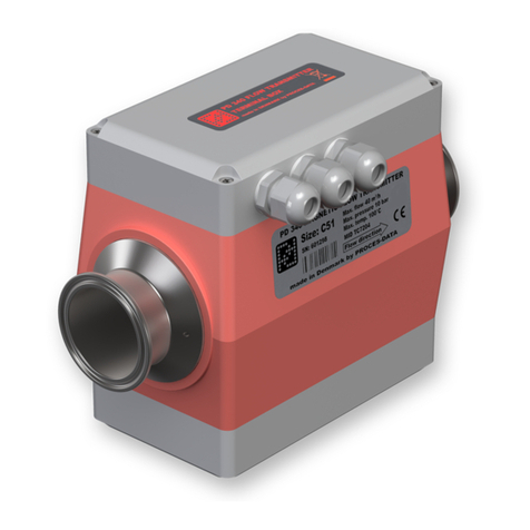
Proces-Data PD 340 User manual

502 010 05
PROCES-DATA A/S
NAVERVEJ 8-10, DK-8600 SILKEBORG • Tel. +45-87 200 300 • Fax+45-87 200 301 • info@proces-data.com • www.proces-data.com
Flow Transmitter
PD 340
Manual
GB

502 010 05
© Copyright by PROCES-DATA A/S. All rights reserved.
PROCES-DATA A/S reserves the right to make any changes without prior notice.
P-NET
®
, Soft-Wiring
®
and Process-Pascal
®
are registered trademarks.

502 010 05
Manual Flow Transmitter, PD 340 3/55
Contents
1
General information........................................................................................................5
1.1
Introduction.............................................................................................................5
1.2
Features..................................................................................................................5
1.3
Construction............................................................................................................6
1.4
Operating principles................................................................................................8
1.5
Reducing the influence of varying flow profiles.......................................................9
1.6
Linearizing function...............................................................................................10
2
Function description.....................................................................................................11
2.1
Flow measurement ...............................................................................................11
2.1.1
Test mode.......................................................................................................11
2.2
Volume counter.....................................................................................................11
2.3
Automatic functions...............................................................................................11
2.3.1
Batch Control..................................................................................................11
2.3.2
Flow control.....................................................................................................12
2.3.3
Limit switch .....................................................................................................12
2.4
Temperature measurement ..................................................................................12
2.5
Output1.................................................................................................................12
2.6
Output2.................................................................................................................12
2.7
Output3.................................................................................................................13
2.8
Input......................................................................................................................13
2.9
P-NET Interface....................................................................................................13
2.10
PD 210 display unit...............................................................................................13
3
Display .........................................................................................................................14
3.1
Local display unit, PD 210 ....................................................................................14
3.2
Display registers ...................................................................................................14
3.2.1
Changing register contents.............................................................................15
3.2.2
Configuration and calibration using the PD 210..............................................15
3.2.3
Error readout...................................................................................................15
3.2.4
Construction....................................................................................................15
3.2.5
Assembly drawing for PD 210.........................................................................15
3.3
Flowmeter-Display, PD 4000/340 .........................................................................16
4
Meter selection and Installation....................................................................................17
4.1
Selecting the correct meter size............................................................................17
4.2
Installation and Care of Transmitter......................................................................18
5
Electrical connections ..................................................................................................20
5.1
Power supply........................................................................................................20
5.2
Output1.................................................................................................................20
5.3
Digital output signals.............................................................................................21
5.3.1
Output2...........................................................................................................21
5.3.2
Output3...........................................................................................................22

502 010 05
4/55 Flow Transmitter, PD 340 Manual
5.3.3
Output3, current output...................................................................................22
5.4
Input signal...........................................................................................................24
5.5
Temperature signal, Pt100 ...................................................................................24
5.6
Connecting the display unit, PD 210.....................................................................24
5.7
P-NET fieldbus connections .................................................................................24
6
Variable description .....................................................................................................26
6.1
SoftWire Table......................................................................................................26
6.1.1
Process variables ...........................................................................................29
6.1.2
Configuration and calibration parameters.......................................................32
6.2
Standard settings..................................................................................................37
7
3-phase output signals.................................................................................................38
7.1
3-phase counter without separate error signal......................................................39
7.2
2-phase counter with separate error signal...........................................................39
7.3
Counter with up/down signal and separate error signal........................................40
7.4
Table showing signal mode relationships.............................................................41
8
Applications..................................................................................................................42
8.1
Flow Control .........................................................................................................42
8.2
Batch control using the PD 210 display................................................................44
9
Fault finding .................................................................................................................46
9.1
Error detection......................................................................................................46
9.2
Typical errors........................................................................................................46
9.2.1
Flow Transmitter with PD 210 display unit......................................................46
9.2.2
Flow Transmitter without display unit..............................................................47
10
List of spare parts ........................................................................................................48
11
Specifications...............................................................................................................49
11.1
Flow measurement...............................................................................................49
11.2
Power Supply........................................................................................................49
11.3
Liquid....................................................................................................................50
11.4
Measurement of temperature ...............................................................................50
11.5
Environment .........................................................................................................50
11.6
Approvals..............................................................................................................50
11.7
Dimensions...........................................................................................................51
11.8
Maximum flow rates and weight............................................................................51
11.9
Material.................................................................................................................51
11.10
Connections..........................................................................................................51
12
Appendix 1...................................................................................................................52
12.1
Memory types.......................................................................................................52
13
Appendix 2...................................................................................................................53
14
Index............................................................................................................................54

502 010 05
Manual Flow Transmitter, PD 340 5/55
1 General information.
1.1 Introduction
The PD 340 Flow Transmitter is a precision meter for the volumetric measurement of liq-
uids that are electrically conducting.
The rugged construction of the transmitter makes it suitable for installations where solid par-
ticulates make up part of the liquid for measurement.
This manual is applies to PD 340 Flow Transmitters that utilise the ‘Version 2’ electronics
module.
1.2 Features
• Sanitary design
• Maintenance-free, no moving parts
• Automatic zero point correction
• High accuracy, even at very low flow rates
• Bi-directional flow
• Volumetric measurement in m3, litres, U.S. gallons etc.
• Pulse output to an electronic counter, 0-1000 pulses per second
• Pulse output to an electromechanical counter, 0-10 pulses per second
• Current output, 4-20 mA (extended version)
• Batch control function
• Limit switch function
• Flow regulator function (PI controller)
• Practically no loss of pressure
• A PD 210 display unit can be simply connected. The PD 210 unit can display accumu-
lated volume, setpoint for batch control or PI regulator, flow rate, temperature, etc.
• Count stop/clear logic input function.
• Temperature measurement using an external temperature sensor
• Temperature compensated flow measurement
• Continuous Selftest, which can be monitored through P-NET
• P-NET Fieldbus Communication (IEC 61158 Type 4)
• EMC approved (DS/EN 61000-6-2) (DS/EN 61000-6-3)
• Vibration approved (IEC 60068-2-6 Test Fc)

502 010 05
6/55 Flow Transmitter, PD 340 Manual
1.3 Construction
The PD 340 Flow Transmitter consists of three parts:
• Meterhead
• Electronic module
• Terminal box
The electronic module and the terminal box are the same for all sizes of transmitter.
The Meterhead consists of a stainless metering pipe with clamp connections. Two magnet
coils are mounted external to the metering pipe. Two stainless electrodes are mounted inside
the metering pipe.
The measuring section is designed with a square measurement chamber, which prevents
changes in flow profile affecting meter accuracy (see the following sections, Operating prin-
ciples, and Reducing the influence of varying flow profiles, for details). Hence the transmitter
has a wide range of flow rates within its linear accuracy. Changes from laminar to turbulent
flow do not affect the linear accuracy, and changing viscosity has no affect on meter accu-
racy. The calibration of the meterhead is carried out during manufacture using a computer
controlled calibration facility.
The Electronic Module is available in two versions, standard and extended with current out-
put or 3-phase output. See appendix 1 for further details.
The standard version has two pulse output signals and one logic input. The transmitter can
also be directly connected to a display unit.
In the extended version, one of the outputs can be configured either for pulse output or ana-
logue current output, 4-20 mA.
The extended version can also be configured for 3-phase output. In this mode the normal
separate pulse output signals are transformed to a combined 3-phased output signal.
The extended version has a built-in P-NET Fieldbus interface (IEC 61158 Type 4), which can
be used for configuration, or for central data collection or control.
The Terminal Box is completely separated from the electronic module. Connections can
therefore be changed without disruption to the electronics. All terminals within the terminal
box are clearly marked with both number and function.
The box is also equipped with 3 cable glands, type PG 11.

502 010 05
Manual Flow Transmitter, PD 340 7/55
PD 210
7 8 9
E 4 5 6
1 2 3
CE 0
,
+/-
=
FLOW TEMP. VOL.1 SETP.
T.C.
FLOW VOL.2
DISPLAY FOR
FLOW TRANSMITTER
COUNTER
24 V
+
Temperature
detector
P-NET
interface
Electronic module
Terminal box
Meterhead
Clamp
connection
2 wire
+ screen
2 wire
24 V battery
or
Transformer
Mains
supply
PC
Flowmeter-Display
PD 210
Control valve/
Frequency
controller (Pump)/
Instrument
Figure 1: System diagram

502 010 05
8/55 Flow Transmitter, PD 340 Manual
1.4 Operating principles
The meterhead consists of a metering pipe and two magnetic coils. When a current is applied
to the coils a magnetic field is produced at right angles to the metering pipe.
With a conductive liquid flowing through the metering pipe an electrical voltage is induced
and measured by two electrodes mounted in the metering pipe. This voltage is proportional to
the average velocity of flow and therefore to the volume flowing.
The PD 340 Flow Transmitter utilizes a square measurement chamber. The shape of the
measurement chamber significantly reduces the influence of viscosity, type of liquid, and flow
profiles (see details in the next section, Reducing the influence of varying flow profiles).
Practical tests with the PD 340 confirm that it is not necessary to recalibrate the meter when
changing product, such as from water to milk. This would normally be necessary when using
magnetic flowmeters that have traditional round measuring chambers.
Ue
B
V
Current
genera-
tion
551 098 01
D
Figure 2: Operating principles
• Ue = K x B x V x D
• Ue = voltage across electrodes
• K = system constant
• B = magnetic field
• V = average velocity
• D = distance between electrodes
The micro-processor in the transmitter controls the current generator, keeping the magnetic
field constant. The voltage across the electrodes is amplified and converted to a digital value
from which the micro-processor calculates the liquid flow.

502 010 05
Manual Flow Transmitter, PD 340 9/55
1.5 Reducing the influence of varying flow profiles
When a liquid flows through a pipe, its velocity tends to vary from zero along the pipe wall
up to its maximum through the centre of the pipe.
The velocity profile depends on the actual flow velocity together with the viscosity of the
liquid.
When the flow rate is low, the velocity profile takes the shape of a parab-
ola. This is called laminar flow. If the flow rate is gradually increased, the
flow profile also changes gradually, still maintaining the laminar flow pro-
file, until it reaches the critical velocity. At this flow rate, the flow profile
will, via a transition phase, change from laminar to turbulent flow with the
formation of eddies and chaotic motion, which do not contribute to the
volume flow rate. The two types of flow profile are illustrated on the figure
to the right. Precisely when the liquid reaches the critical velocity and
changes to turbulent flow, depends on the diameter of the pipe, and on
the viscosity and density of the liquid. For cream, for example, the visco-
sity strongly depend on the temperature and the percentage of fat, and it
is therefore not possible to predict the flow profile at any given flow rates.
The technique used to avoid an unknown flow profile from affecting the accuracy of a
measurement, consists essentially of measuring the average velocity of the liquid through-
out the full cross section of the pipe, hence registering all the liquid passing through it.
The average measurement is achieved in a PD 340 by using a
square measurement chamber, where each of the two electrodes are
designed to measure across the complete cross section of flow.
This is in contrast to flow meters having a circular cross section and
point-type electrodes. Here the ‘field of view’ between the electrodes
is limited to only involving the liquid passing directly between the
electrodes. Its calibration is therefore conditional on a particular
known flow profile.
Measures over
the en
tire cross
section of the
chamber
Field of view

502 010 05
10/55 Flow Transmitter, PD 340 Manual
1.6 Linearizing function
Because of its construction as described in the previous section, the PD 340 Flow Trans-
mitter is, by its very nature linear, even without any electronic compensation.
However, most of our customers prefer not to use anything smaller than 25 mm as a pipe
diameter, even for very low flow rates. Therefore, to further improve linearity, a special
compensation function has been developed and implemented within the ‘Version 2’ elec-
tronics module. Consequently, when this function is enabled1,, the PD 340 can now be
used even at very low flow rates, but still offering the same well-known high accuracy
measurement as normally experienced with higher flow rates.
During the flow calibration at the factory, the linearizing curve is calculated and downloaded
to the electronic module. For this reason, all new PD 340 Flow Transmitters will hold the
data needed by the linearizing function, when they are delivered as complete meters, i.e.
meterhead and electronic module. If one of the new electronic modules needs to be
mounted on a meter head with which it was not originally tested, and the linearizing func-
tion is to be used, data for the linearizing function can be downloaded to the electronic
module using a PC with VIGO version 5.6 or higher installed (valid for extended version
electronics only).
The graph below shows the linearizing curve for a specific flow transmitter. If this flow
transmitter measures the flow rate at 20% of full scale, this value will be compensated by
–0.01% of full scale.
1Enable/disable: Register E7, Dig. 5.

502 010 05
Manual Flow Transmitter, PD 340 11/55
2 Function description
The Flow Transmitter holds a number of internal functions and connections for external sig-
nals. The functions may be selected by keying in a set of configuration parameters. Calibra-
tion parameters may also be set. The data may be entered via a display/keyboard unit or via
P-NET.
The Flow Transmitter may be scaled to operate in any volumetric units, Litre, m3, Gallon etc.
The flow rate may be selected to be displayed as volume unit/hour or /minute.
2.1 Flow measurement
The flow rate may be filtered to stabilize the readout of an unstable flow. Flow rates below 0.2
% of full scale may be ignored. This may be useful to avoid totalizing the volume during long
periods with no flow (see configuration of function selector Code3).
Flow is measured in both directions. Flow in the direction of the arrow on the meter head will
be indicated as positive flow. Optionally, negative flow can be ignored and set to zero to pre-
vent downward volumetric totalisation (see configuration of function selector Code3).
To compensate for the expansion of the liquid, the Flow Transmitter may be configured to
indicate a flow as if the liquid temperature was at 4 °C (see also T.C. Flow).
2.1.1 Test mode
The Flow Transmitter may be switched into test mode. During installation and service, the
test mode may be used to simulate that liquid is flowing in the pipe system. All output signals,
pulse signals as well as the current signal, will act as if the liquid flow was present. This way,
all internal functions, external signals and cable connections may be checked (see configura-
tion of function selector Code2).
2.2 Volume counter
The Flow Transmitter utilizes two independent totalizers, Volume1 and Volume2, which indi-
cate the measured volume since each were cleared. Each volume counter may be independ-
ently cleared or preset to a specific value (see further details in the Volume1 description).
2.3 Automatic functions
A number of automatic functions are selectable in the Flow Transmitter. Only one of the func-
tions should be selected (see configuration of function selector Code2 about how to select
each function).
2.3.1 Batch Control
The Flow Transmitter has a built-in batch control function, and can therefore easily be used to
control the dosing of a specified volume. The required volume is keyed into a setpoint regis-
ter. A digital input on the Flow Transmitter may be used to start the batch control. A digital
output, Output2, opens the dosing valve or starts a pump. When the setpoint volume is

502 010 05
12/55 Flow Transmitter, PD 340 Manual
reached, the output is switched off and the valve is closed or the pump stops. The Volume2
counter shows the dosed volume (see also the Batch control application example).
2.3.2 Flow control
In systems where it is desirable to have a constant flow, the built-in Flow Control function may
be used to control a valve or pump directly. The required flow rate is keyed into a setpoint
register and the internal PI controller will control the valve or pump by means of the current
output signal (4-20 mA) (see the Flow control application example)
2.3.3 Limit switch
The Flow Transmitter has a built-in limit switch function. This function may be used to indicate
whether a measuring value is below or above the value in the setpoint register. As an exam-
ple, this may be used to indicate a high/low flow rate. The indication may appear on a digital
output, Output2, as ON or OFF (see configuration of function selector Code2 to select this
function for Output2).
2.4 Temperature measurement
The Flow Transmitter can measure temperature by connecting an external Pt100 tempera-
ture sensor. The temperature may be read in a register as °C or °F (see configuration of func-
tion selector Code3). This would be necessary for temperature compensated flow measure-
ment.
2.5 Output1
Output1 is a power supply output, which can be used to supply nom. 24 V DC to an external
counter or relay circuit (see further details in section 5.2).
2.6 Output2
Output2 can be selected for one of several functions:
• Pulse signal, 0-10 Hz. The signal may be taken to a counter, electronic or electro-
mechanical, for indication of the total volume, e.g. in litres (see section 5.3.1 Output2).
• Sign for Output3. The signal indicates the flow direction. The output is switched OFF,
when the flow is positive. By means of an UP/DOWN-counter, this signal may be used
for the totalizing of the volume flowing with a sign.
• Control signal from the Batch control function.
• Control signal from the Limit function.
• Error free measurement signal. The output signal is ON if no error is present.
• The output may be controlled directly via P-NET.
(See configuration of function selector Code2)
Further details for connecting Output2 can be found in section 5.3.1 Output2.

502 010 05
Manual Flow Transmitter, PD 340 13/55
2.7 Output3
Output3 may be used as a digital signal output or as an analogue 4-20 mA current output.
When used as a digital signal, it may be used as a fast pulse signal (0 - 1000 Hz) for external
counter circuits (see scaling example in chapter 6), or it may be controlled directly via P-NET.
Further details for connecting Output3 can be found in section 5.3.2 Output3.
2.8 Input
The transmitter has a logic input, Input1, which can be selected for one of several functions:
• Stop counters. The signal may be derived from an air detector, and is then used to
make the transmitter stop counting, when there is air in the liquid.
• Clear Volume2 counter. The input can be used in batch control, to start the Batch func-
tion and clear the batch volume counter.
• Manual/Automatic mode for PI controller. The input can be used to set the operation
mode for the PI controller.
(See configuration of function selector Code3).
Further details for connecting Input1 are found in chapter 5.4 Input signal.
2.9 P-NET Interface
The extended version of the Flow Transmitter utilizes a P-NET fieldbus communication inter-
face, which enables the Flow Transmitter to be connected directly to a P-NET fieldbus net-
work designed for process control and data-collection. P-NET is an international standard
(IEC 61158 Type 4).
Through P-NET it is possible to display and change all the internal data within the Flow
Transmitter (see a complete list in the Variable Description).
The PD 4000 Flowmeter-Display utilizes the P-NET interface for data exchange between the
Flowmeter-Display and connected Flow Transmitters. It is possible to change data and to
select various functions in each Flow Transmitter. The memory in the Flowmeter-Display is
equipped with a battery backup, which will hold the measured data during a power failure.
The P-NET interface may also be used for data collection, e.g. by a PC. The PC can be
equipped with a P-NET interface device, which makes it possible to directly access any vari-
able in the Flow Transmitter and other connected P-NET modules while running a PC pro-
gram.
2.10 PD 210 display unit
The PD 210 is a local display unit, which is connected directly to the Flow Transmitter. From
this unit it is possible to display the flow rate, volume counters, temperature, setpoint etc. Fur-
thermore the PD 210 display unit may be used to change setpoint values and to perform a
complete configuration of the Flow Transmitter (see description in section 3).

502 010 05
14/55 Flow Transmitter, PD 340 Manual
3 Display
Various options are available for displaying information from the PD 340 Flow Transmitter.
The Flow Transmitter may be controlled and supervised via the P-NET interface (requires the
extended version), and all data may then be accessed. Another solution is to connect a local
PD 210 display unit to the Flow Transmitter. Then only the main data is accessible.
3.1 Local display unit, PD 210
The PD 210 display unit can be directly connected to the transmitter. With this unit con-
nected, it can perform a number of different functions.
• Display of data from the transmitter, e.g. flow or volume.
• Change data in the transmitter, e.g. contents of volume register or SET-point register.
• Configuration and calibration, e.g. setting of the size of the meterhead or the function
of the output signals.
• Readout and reset of an internal error code.
The display unit is connected to the Flow Transmitter with a two-wire cable, up to a length
of 100 m. The display unit is supplied with power via this cable. It also carries the exchange
of data between the Flow Transmitter and the display unit.
3.2 Display registers
The contents of 8 different
registers in the transmitter
can be displayed on the unit.
A touch on one of the 8 but-
tons under the display se-
lects whichever register
needs to be read. The dis-
play indication is automati-
cally updated about once
per sec. Additional de-tails
may be found in section
6.1.1.
FLOW TEMP. VOL.1 SETP.
T.C.
FLOW VOL.2
551 101 01
DISPLAY FOR
FLOW TRANSMITTER
PD 210
7 8 9
E 4 5 6
1 2 3
CE 0
,+/-
TEST
=
Reg. No.
Name Function SWNo
1
2
3
4
5
6
7
8
FLOW
T.C.FLOW
TEMP
“blank”
VOL.1
VOL.2
SETP.
”blank”
Liquid flow, e.g. in m3/h
Temperature compensated flow
Temperature in °C or °F
Available register
Volume, result of totalization, e.g. in m3
Volume for comparing with SET-point, e.g. in m3
SET-point, e.g. in m3
Instant Flow
$11
$12
$13
$14
$15
$16
$17
$18

502 010 05
Manual Flow Transmitter, PD 340 15/55
3.2.1 Changing register contents
If a change in the contents of a register is required, the register must first be displayed. Then
the desired contents are entered, followed by a press on the =button. This gives a blank dis-
play for approx. 1 sec., and then the new contents are displayed in the normal way.
3.2.2 Configuration and calibration using the PD 210
The Flow Transmitter contains 8 configuration registers. See also section 6.1.2 for a detailed
explanation and purpose for these registers (SoftWire number 20 to 27). If it is required to
display the contents of a configuration register, press the Ebutton, which will turn the display
blank. Then press a numeric key between 1and 8to choose the desired configuration re-
gister. The number of the configuration register appears in the first digit of the display, and
the contents of the register in the rest of the display. Changing the contents of a register are
performed by keying in the new contents, and then presssing the =button.
3.2.3 Error readout
The user is informed of an error by an "A" for ALARM appearing in the first digit of the dis-
play. By pressing the "TEST" button the display will show an error code of two digits, indicat-
ing the type of error. The test system ensures that the alarm will not be cancelled before the
error code has been displayed by pressing the "TEST" button, even though the error may
have disappeared. By pressing the "TEST" button once again, the display will show "00" if the
Flow Transmitter is now error free. The error code on the display is only updated by
re-pressing the "TEST" button. A complete list of error codes is given in section 6.
3.2.4 Construction
The display unit consists of an LCD display, a keyboard, and electronics for exchange of data
with the transmitter and control of the display and the keyboard.
The unit is built into a case of NORYL PPO, sealed to IP 65. The dimensions of the enclosure
are LxHxD = 144 x 72 x 8 mm. (Standard dimensions for cabinet mounted instruments).
3.2.5 Assembly drawing for PD 210
Note: Please observe that the M3
mounting screw holes are only 4
mm. deep.
Do NOT screw down beyond this
length. This may damage the dis-
play unit.
55.0
127.0
4.0
R18.0
4 holes
for M3 screw
14.6
Cut-out section
in panel
for connections

502 010 05
16/55 Flow Transmitter, PD 340 Manual
3.3 Flowmeter-Display, PD 4000/340
The Flowmeter-Display is based on a PD 4000 P-NET Controller and is designed to display
data from PD 340 Flow Transmitters. Furthermore it is possible to change data and to select
various functions in the Flow Transmitters.
The displayed data could, for example, be flow or volume, or perhaps a setpoint or filter con-
stant might be selected for modification.
PD 4000/340
7
4
1
0
8
5
2,
9
6
3
+/-
=
CE
608149
FLOWMETER-DISPLAY
METER BMETER A
FLOW
BATCH
TOTAL
METER C
TEMP
SETUP
START
PRINT
STOP CLEAR
Prev. Page
551 102 01
Up to three Flow Transmitters may be selected and supervised simultaneously using the
Flowmeter-Display. The Flowmeter-Display is connected to the Flow Transmitters within a
P-NET Fieldbus system. Therefore the Flow Transmitters must have extended version elec-
tronics.
A standard configuration for a PD 340 Flow Transmitter is stored in the Flowmeter-Display
and can be transferred automatically via P-NET to a new Flow Transmitter in the system. The
standard configuration can be altered to match a specific customer configuration.
The actual configuration for each of the selected Flow Transmitters can be listed in clear text
on the display.
Please refer to the Flowmeter-Display manual (502 071) for additional information.

502 010 05
Manual Flow Transmitter, PD 340 17/55
4 Meter selection and Installation
4.1 Selecting the correct meter size
The complete PD 340 Flow Transmitter family has a very large measuring range. It is nor-
mally recommended that a particular transmitter size is selected so that it will operate in the
upper half of its measuring range. This is due to the fact that the influence of zero point error
is relatively higher at low flow rates. This applies to any flow transmitter on the market. How-
ever, it is possible to use the PD 340 even at very low flow rates, whilst still obtaining high
accuracy. Flow measurement down to 1 % of maximum flow rate for the Flow Transmitter is
now possible (100:1 turndown), when the linearizing function is enabled (refer to Linearizing
function in section 1).
Practical examples from different installations indicate that actual expected operational flow
rates do vary. It is therefore recommended that the calculated maximum flow rate should not
exceed 90 % of the specified maximum flow rate for the selected Flow Transmitter. Excep-
tions may be made if the flow rate is well known and very stable.
As a rule, a Flow Transmitter with a pipe dimension equal to the rest of the piping system
should be selected.
The size of the meterhead should be selected according to the maximum flow rate. This
maximum flow rate must be the absolute maximum flow rate during operation, cleaning,
startup etc. The smallest possible transmitter is then chosen for that maximum flow rate. This
will ensure optimum measurement accuracy. If the metering section is smaller than the pipe-
work in the installation, the connecting pieces should be tapered.
A Flow Transmitter should not be installed in a pipe construction where the pipes are smaller
than the pipes in the connections.
If two products are mixed before measuring, the mixed product must be a homogenous liquid
before entering the Flow Transmitter to ensure maximum accuracy.
The Flow Transmitter is available in 5 different sizes as shown in the table below:
Max. flow rate:
C 25 C 38 C 51 C 63 C 76
8 m
3
/h 20 m
3
/h 40 m
3
/h 80 m
3
/h 120 m
3
/h
Note: The max. flow rate for the Flow Transmitter must NEVER be exceeded, otherwise
the meterhead may be damaged.

502 010 05
18/55 Flow Transmitter, PD 340 Manual
4.2 Installation and Care of Transmitter
The transmitter should be installed within the pipe work system such that the metering pipe is
always filled with liquid, because the transmitter can register some flow, even when the meter
is empty.
551 198 01
Ensure that the valve is always mounted
after the Flow Transmitter (downstream).
As the transmitter will measure any air in the liq-
uid as a part of the total volume, the volume of
the air must be reduced to an absolute minimum.
To help achieve this, the transmitter should be
located in the pipe work system at the point of
maximum pressure. Here the volume of the air
will be at a minimum and thus the influence of air
on the measurement will also be at a minimum. It
is therefore recommended that control valves, or
other restrictions that might create a pressure
drop, are mounted after the Flow Transmitter.
Even when there is no air in the liquid it is impor-
tant to ensure that the pressure is sufficiently high,
otherwise cavitation may occur in the transmitter.
Not only will this influence the accuracy, but it is
also destructive to the Teflon lining.
The graphs to the left show the
required minimum gauge pres-
sure (measured in the pipeline
after the Flow Transmitter) as a
function of flow at different op-
erational temperatures. Always
ensure that the gauge pressure
is well above the curve defined
by the relevant operational tem-
perature. Please observe that
the dotted parts of curves fall
outside the allowable opera-
tional specifications and are only
shown as extrapolations from
permitted values. Using the
transmitter under these condi-
tions may cause damage, which
will not be covered under the
product guarantee.

502 010 05
Manual Flow Transmitter, PD 340 19/55
If heavy vibrations can occur in the pipe work caused perhaps by resonance from pumps, or
a pulsating pressure in connection with, for example, a homogenizer or a positive displace-
ment pump, then vibration damping is required, or the transmitter should be mounted some-
where else where there is less variation in pressure.
If the liquid contains air, an air eliminator should be mounted before the Flow Transmitter.
The transmitter can be mounted both horizontally and vertically. No air must be trapped in the
meter head. The positive flow direction is indicated by an arrow on the meterhead.
Vertical mounting Horizontal mounting
(seen from one side)
551 103 01
With vertical mounting, upward flow is recommended. The reason for this is that any air within
the liquid will easily follow the liquid in its upward direction, which would not be the case with
downward liquid flow. With horizontal mounting, orientation as shown on the left is recom-
mended. Mounting the meter as shown in the figure to the right would mean that one of the
electrodes would be positioned at the top of the meter tube, and any air bubbles could cause
the electrode to loose contact with the liquid.
To create the best conditions for precise metering, and to maximise the lifetime of the trans-
mitter, a straight pipe run of at least three times the pipe work diameter should be mounted
upstream and downstream of the transmitter. This is especially important when running at
high temperature and high flow rate, since the risk of cavitation is increased with turbulent
flow.
When selecting the location of the transmitter it must be ensured that the ambient tempera-
ture is within the specified limits. Finally, the transmitter should be installed such that the elec-
tronic module and the terminal box can be fitted and dismantled in situ.
Note: The clamp connections must be loosened completely before the transmitter is
rotated. Otherwise the meterhead may be fatally damaged.
Precautions must be taken to ensure that neither the electronic module, nor the meterhead,
nor the terminal box is exposed to moisture, when the transmitter is dismantled. To prevent
moisture, the cables must be mounted correctly in the glands. The electronic module and the
terminal box must be carefully mounted with all screws tightened.
The Flow Transmitter supply should always be connected, as heat developed in the elec-
tronic module prevents any condensation, which could damage the transmitter. The transmit-
ter should therefore be powered up as soon as possible after mounting.

502 010 05
20/55 Flow Transmitter, PD 340 Manual
5 Electrical connections
The figure below shows the terminal board with all the possible electrical connections for the
Flow Transmitter. The program enable switch, SW1 located in the upper left corner, must be
in the ON position when configuring and calibrating the Flow Transmitter. After configuration
and calibration, the switch must be set in the OFF position.
Figure 3: Electrical connections in Terminal Board
5.1 Power supply
The power supply for the Flow Transmitter can be either 24 V DC or 24 V AC. Terminal
boards marked ‘PD 381-02’ will have a 2-position switch, SW2. If SW2 is set to ‘AC’ (factory
setting), the supply voltage can be either AC or DC. If SW2 is set to ‘DC’, it must be supplied
with DC. The ‘DC’ setting can be used on mobile applications to comply with OIML require-
ments.
If the conductivity for the liquid is below the specified 5 µs/cm, it might still be possible to
measure the flow. To do this, the Flow Transmitter must be connected to a separate DC
power supply with the -24 V DC terminal connected to the piping system.
This will increase the sensitivity, and flow measurement may still be possible.
5.2 Output1
Output1 on the terminal board is a voltage
supply, which can be used to supply an ex-
ternal counter circuit, relays or current de-
vices (4-20 mA).
The voltage at the output can vary from 20
to 40 V DC, depending on the power supply
voltage (Supply voltage - 2 V as minimum).
+
-~
~
RPTC
zener
D
51 V
6-
5+
2
1
Output 1
Power
input
Bridge circuit
551 104 01
Figure 4: Power supply output electrical
The voltage supply is connected directly to a bridge circuit, which rectifies the power supplied
to the transmitter. The output is protected with a zener diode and a current-limiting resistor in
the same way as the pulse outputs. Furthermore, the output is isolated from the internal elec-
tronics by a transformer. The output is not isolated from the power source supplying the
transmitter.
Other manuals for PD 340
1
Table of contents
Other Proces-Data Transmitter manuals
Popular Transmitter manuals by other brands
NIVELCO
NIVELCO NIPRESS DRD-6 Series user manual

Audio Ltd.
Audio Ltd. HX2040 user guide
SMAR
SMAR TT302 Operation, maintenance & instruction manual

Emerson
Emerson Rosemount 3051S Series quick start guide
Nautel
Nautel VS300 troubleshooting manual

Mitsubishi Electric
Mitsubishi Electric PAC-SF46EPA installation manual
