2
AntennaInstallationForDT01*Kit
A DT01* antenna must be installed to the PTAC to allow
operation of either the DS01* remote RF thermostat or a
DD01*combinationPIRmotionsensoranddoorswitch.
Preparation
1. Disconnect power to the unit by unplugging the power
cord at the wall outlet or subbase, or disconnect power
at the fuse box or circuit breaker.
2. Ifthecabinet front is screwedtothechassis, remove the
1/4”screw (or screws) locatedbehindthe inlet grille.Pull
theinlet grille forward from the top of the grille to access
screw(s).
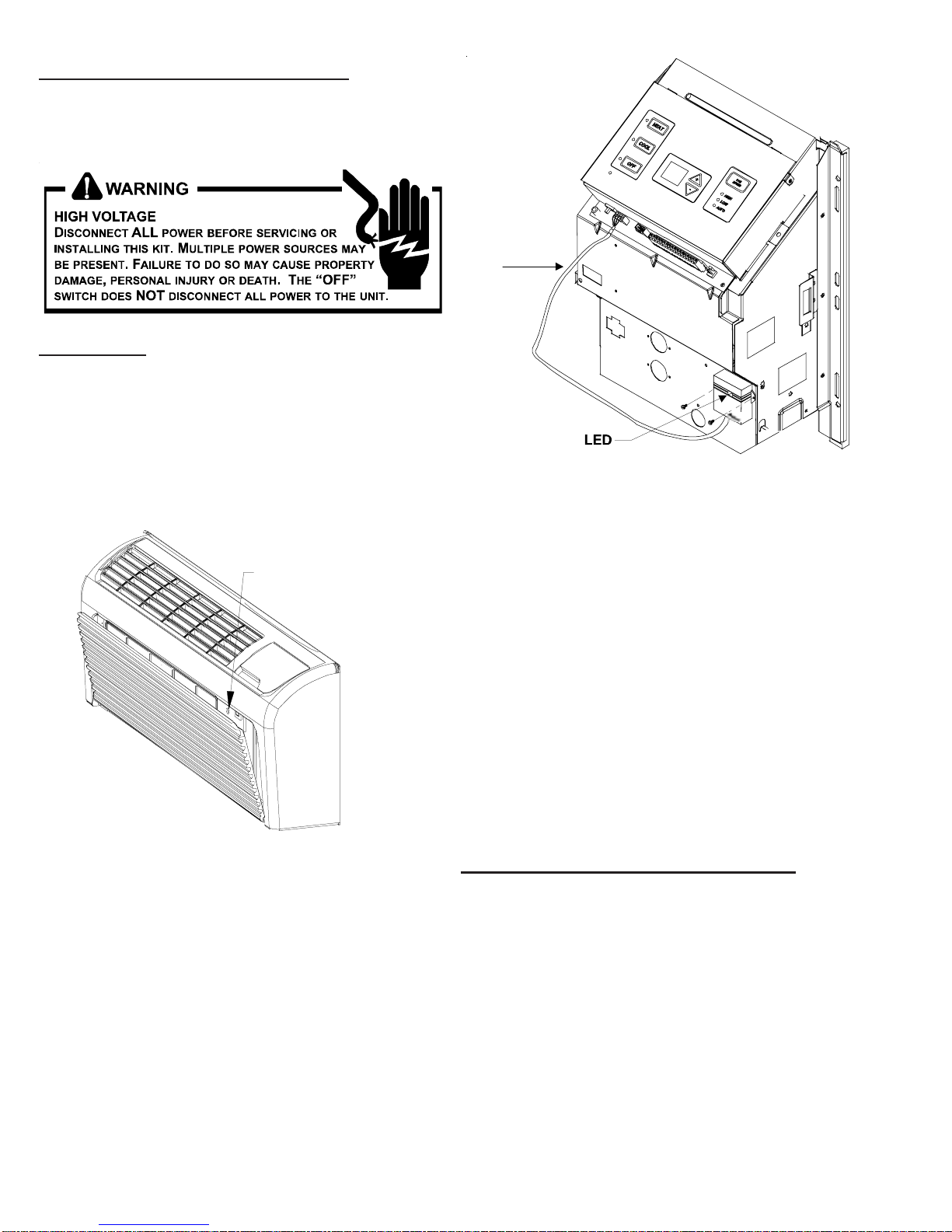
FRONT MOUNTING
HOLE
3. Remove cabinet front from chassis by tilting the bottom
ofthefront forward, liftingslightlyupand forward.
4. Mount the antenna as high up on the control panel as
possible and as far to the right as possible in a location
that will not interfere with the reinstallation of the PTAC
polymer room front. Mark holes for screw location. Re-
move antenna housing and drill two1/8”holes where
marked.
Wire
DT01* Mounting
5. Removeantenna cableandroutecablethroughopening
inbottomof antenna housing.
6. Mount antenna housing with two screws as shown in
figure. (NOTE:TheAmana®brandlogoshouldbein the
lowerright handcorner).
7. Plug wire harness from antenna into connector on the
control board to the right of the master switch, being
careful not to bend and/or break the wires when you
connect the cable to the PTAC. Gently push into place
with your thumb nails.
8. Restorepower to the PTAC unit.
9. Reinstallthe polymer roomcover.
NOTE:The LEDmustbeorientedatthetopofthe antenna
housingforproperunitoperation.
ThermostatInstallationforDS01*Kit
NOTE: ADT01* must be installed in the PTAC unit for the
DS01*tobe operable.
Skip these steps if not installing.
1. Selectthermostatmountinglocationaboutfivefeetabove
the floor, on an inside wall, out of direct sunlight, away
fromsourcesof radiant heat(lamps,fireplaces, heating
and air conditioning equipment, etc.), away from win-
dows or door to the outside, and avoid areas with poor
air circulation. Ensure location is out of the path of foot
trafficwhereapersonmightaccidentally bump into the
thermostatsanddamage the device.