Hinweis
..................................................
• Detaillierte Angaben zum Produkt, eine ausführliche
Beschreibung, die Software für das Gerät (IODD)
sowie die Konformitätserklärung finden Sie im Inter-
net: www.festo.com.
• Einbau und Inbetriebnahme nur von qualifiziertem
Fachpersonal, gemäß Bedienungsanleitung.
5
6
7
4
2
2
3
1
0,5 Nm
ß1,5
0,3 Nm
8
2
9
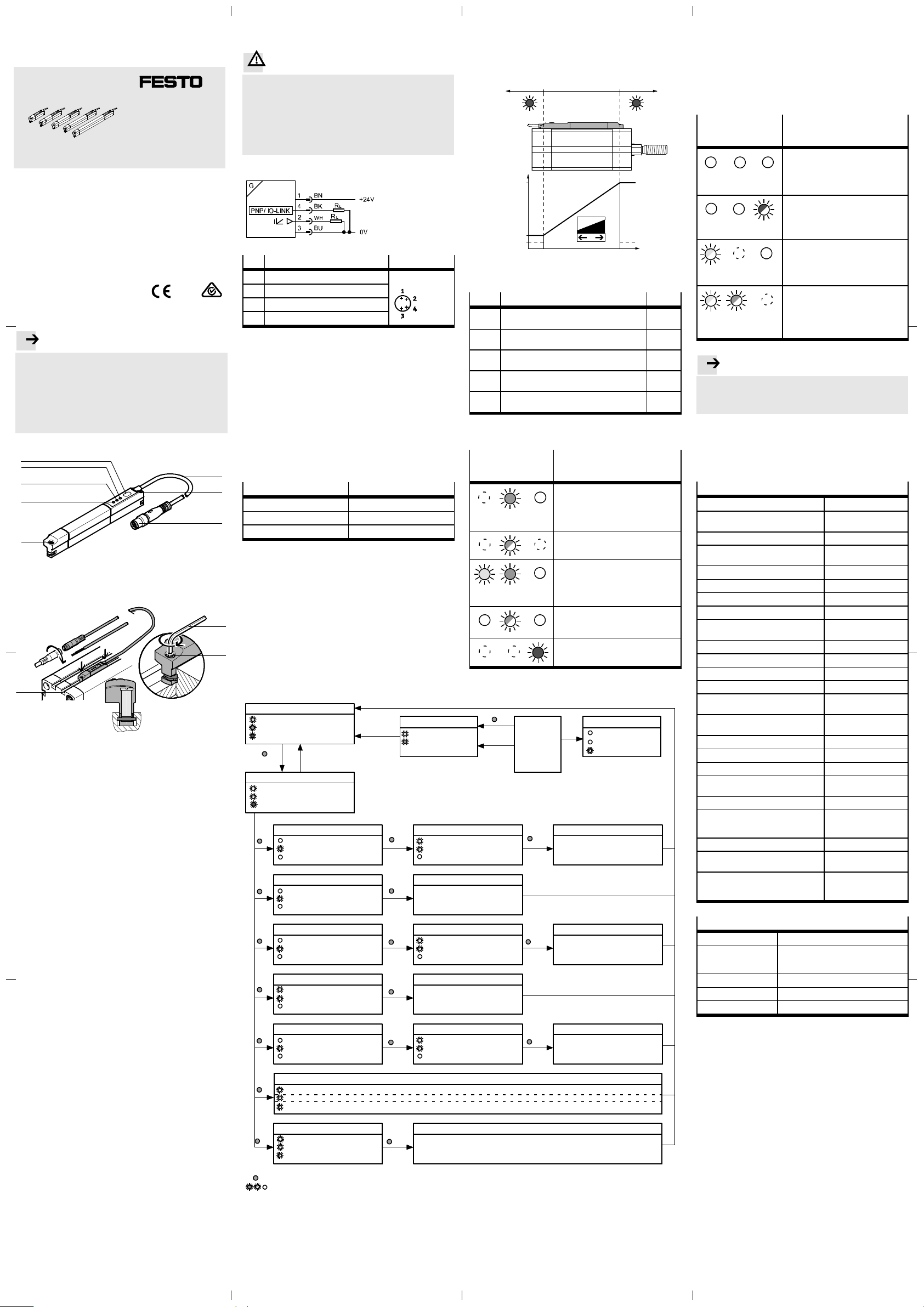
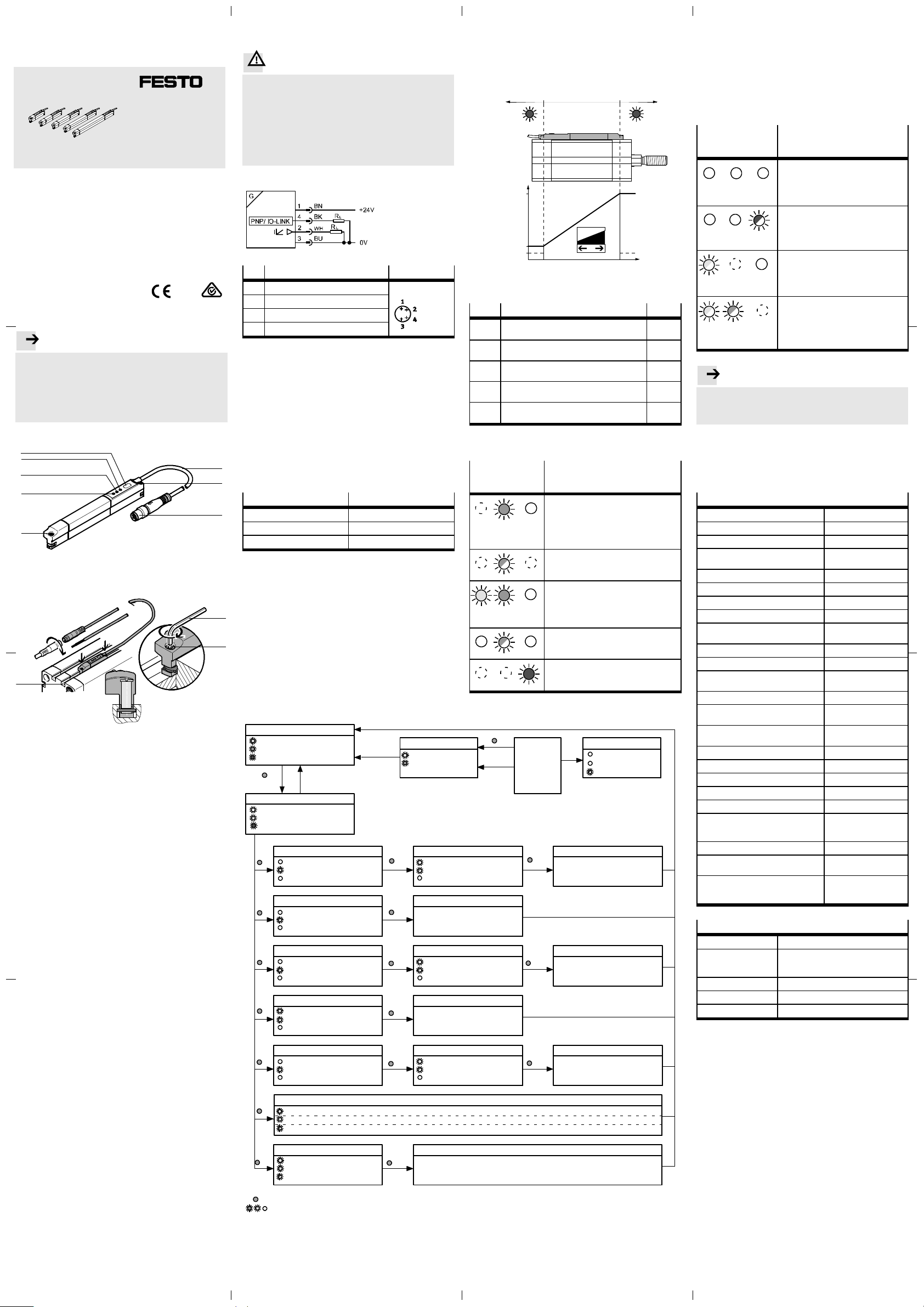
1Anschlusskabel
2Befestigungsschraube
3Stecker M8, drehbar
4Rote LED: Statusanzeige
5Grüne LED: Anzeige Betriebsbereitschaft
6Gelbe LED: Anzeige Schaltzustand
7Bedientaste
8Innensechskant-Schraubenschlüssel
9T-Nut (profilnut 8)
1 Funktion und Anwendung
Der Positionstransmitter SDAT-MHS dient bestimmungs-
gemäß zur berührungslosen Erfassung der Kolbenposition
magnetisch abfragbarer Antriebe. Geeignet sind Antriebe
von Festo mit T-Nut (Profilnut 8) sowie Rundzylinder und
Zugankerzylinder mit Befestigungsbausätzen.
Der Positionstransmitter SDAT-MHS erfasst das Magnet-
feld des Kolbenmagneten und nimmt im Erfassungsbe-
reich die Kolbenbewegung kontinuierlich auf.
Als Ausgangssignale stehen zur Verfügung:
– analoges Stromsignal (4 ... 20 mA),
– programmierbarer Schaltausgang (24 V),
– IO-Link Kommunikationsmodus.
Das Gerät ist nicht für den Einsatz als Sicherheitsbauteil
geeignet!
2 Voraussetzungen für den Produkteinsatz
– Verwenden Sie das Produkt im Originalzustand ohne
jegliche eigenmächtige Veränderung.
– Setzen Sie den SDAT-MHS nur für die geeigneten
Antriebe von Festo ein (www.festo.com/catalogue).
– Vermeiden Sie magnetische Körper im nahen Umfeld
des Positionstransmitters. Diese können das Magnet-
feld und damit das Sensorverhalten beeinflussen.
– Das Gerät ist für den Einsatz im Industriebereich
vorgesehen. Im Wohnbereich müssen evtl. Maßnahmen
zur Funkentstörung getroffen werden.
Positionstransmitter de..........................
3Einbau
Warnung
.................................................
Verwenden Sie ausschließlich Stromquellen, die eine
sichere elektrische Trennung der Betriebsspannung
nach IEC/EN 60204-1 gewährleisten. Berücksichtigen
Sie zusätzlich die allgemeinen Anforderungen an PELV-
Stromkreise gemäß IEC/EN 60204-1.
Schaltnetzteile sind zulässig, wenn sie die sichere
Trennung im Sinne der EN 60950/VDE 0805 gewähr-
leisten.
Schaltbild und Pinbelegung
Pin Belegung
1Betriebsspannung +24 V DC M8x1, 4-polig
2Analogausgang 0 ... 20 mA
30V
4IO-Link/Schaltausgang (C/Q-Leitung)
1.Setzen Sie den SDAT-MHS in die T-Nut des Antriebs ein.
2.Bewegen Sie den Kolben in eine Endlage der Applika-
tion.
3.Schieben Sie den SDAT-MHS in Richtung des Kolbens,
bis die rote LED erlischt.
4.Ziehen Sie die Befestigungsschrauben handfest an.
4 Inbetriebnahme und Betrieb
1.Schalten Sie die Betriebsspannung ein.
– Die LED leuchten (abhängig von der Kolbenposition).
– Das Gerät ist betriebsbereit.
Werkseinstellung
Parameter Werkseinstellung
Schaltfunktion Keine
Schaltlogik Schließer (NO)
Skalierung Gesamter Erfassungsbereich
IO-Link
Die IO-Link Funktionalität kann nicht über die
Bedientasten am Gerät eingestellt werden. Alle Einstel-
lungen zum Einrichten, in Betrieb nehmen und Parame-
trieren werden in der übergeordenten Steuerung des IO-
Link Masters vorgenommen.
Betrieb Analogausgang und Schaltfunktion
Funktion Analogausgang
Der Analogausgang stellt ein im Erfassungsbereich zum
Kolbenhub wegproportionales Ausgangssignal 4...20 mA
zur Verfügung.
AB C
20 mA
4mA
2mA
0mm xmm
x = maximale Länge des Erfassungsbereichs (typabhän-
gig)
Signal Beschreibung Bereich
0mA IO-Link Betrieb.
Fehler (z. B. Kabelbruch, Parameterfehler).
2mA Kolben nach dem Einschalten der Betriebs-
spannung außerhalb des Erfassungsbereichs.
A,C
4mA Kolben hat den Erfassungsbereich in Richtung
des fallenden Ausgangsstroms verlassen.
A
> 4 mA...
<20mA
Kolben innerhalb des Erfassungsbereichs. B
20 mA Kolben hat den Erfassungsbereich in Richtung
des steigenden Ausgangsstroms verlassen.
C
Statusmeldungen im Normalbetrieb
LED-Anzeige Beschreibung
Gelb Grün Rot
Grüne LED leuchtet: Betriebsbereitschaft
(Gelb: beliebig, Rot: aus) .
– Funktion Analogausgang oder Betriebs-
art Schaltausgang.
– Kolben innerhalb des Erfassungsbe-
reichs.
Grüne LED blinkt mit 1 Hz: Betriebsbereit-
schaft.
– Betriebsart IO-Link.
Gelbe und grüne LED leuchten: Betriebsbe-
reitschaft.
– Schaltausgang geschaltet.
– Kolben im Bereich einer programmierten
Funktion.
Grüne LED blinkt 3 Sekunden mit 3 Hz bei
Drücken der Bedientaste:
Bedientaste gesperrt.
Rote LED leuchtet: Statusanzeige.
– Kolben außerhalb des Erfassungsbe-
reichs.
5Ausbau
1.Schalten Sie die Betriebsspannung ab.
2. Trennen Sie die Anschlüsse vom SDAT-MHS.
3.Lösen Sie die Befestigungsschrauben.
4.Nehmen Sie den SDAT-MHS aus der T-Nut des Antriebs
heraus.
6Störungen
LED-Anzeige Mögliche Ursache / Abhilfe
Gelb Grün Rot
Spannungsversorgung, Verbindungslei-
tung oder Sensor defekt.
– Spannungsversorgung sicherstellen.
– Verbindungsleitung ersetzen.
– Gerät austauschen.
Alle LED aus
Sensor defekt.
– Spannungsversorgung ein-/ausschal-
ten.
– Gerät austauschen.
Rote LED blinkt
Kurzschluss/Überlast am Schaltausgang.
– Kurzschluss/Überlast beseitigen.
Parameterfehler.
– Gerät auf Werkseinstellungen zurück-
setzen.
Gelbe LED blinkt mit 3 Hz
Kommunikationsfehler im IO-Link Modus
– IO-Link Master überprüfen.
– Neustart der Kommunikation.
– C/Q Leitung überprüfen.
Gelbe LED blinkt mit 3 Hz
Grüne LED blinkt mit 1 Hz
Hinweis
..................................................
Erkennt das Gerät während des IO-Link Betriebs einen
Fehler, wird eine Statusmeldung auf den IO-Link Master
ausgegeben. Der IO-Link Ausgang wird nicht gesperrt.
7Zubehör
Zubehör www.festo.com/catalogue.
8 Technische Daten
SDAT-MHS
Zulassung CE, RCM
CE-Zeichen Nach EU-EMV-Richtlinie
Werkstoffhinweis RoHS-konform
Erfassungsbereich
(typabhängig)
[mm] 50/80/100/125/160
Abtastintervall typ. [ms] 1,0
Max. Verfahrgeschwindigkeit [m/s] 3
Auflösung Weg [mm] ≤0,05
Schaltausgang PNP
Wiederholgenauigkeit
Schaltpunkt
[mm] ±0,1
Hysterese [mm] ≤0,3
Analogausgang [mA] 0 ... 20
Empfindlichkeit
(typabhängig)
[mA/mm] 0,32/0,2/0,16/0,128/0,1
Linearitätsfehler typ. [mm] ±0,25
Wiederholgenauigkeit
Analogausgang
[mm] ±0,1
Max.Lastwiderstand
Stromausgang
[Ω]500
Betriebsspannung DC [V] 15 ... 30
Signallaufzeit typ. [ms] <2
Kabellänge [m] 0,3
Leiter-Nennquerschnitt [mm
2
]0,1
Max.Anziehdrehmoment [Nm] 0,5
Werkstoffinformation
Gehäuse
PA-verstaerkt, Polyester,
hochlegierter Stahl rost-
frei, Messing vernickelt
Umgebungstemperatur [°C] –25 ... +70
Umgebungstemperatur bei
UL-Zulassung
[°C] –25 ... +70
Schutzart (nach EN 60529) IP65/IP68
(Bedingung IP68: Prüf-
dauer 24 h)
IO-Link
IO-Link Protokoll V1.1
IO-Link Profil Smart Sensor Profil
Funktionsklassen: 0x8000, 0x8001,
0x8002, 0x8003, 0x8004
Kommunikationsmodus COM3 (230,4 kBaud)
Prozessdatenbreite 2Byte
Porttyp A, 4-pol
SD
T-MHS
Bedienungsanleitung
Original: de
Festo AG & Co. KG
Postfach
73726 Esslingen
Deutschland
+49 711 347-0
www.festo.com
1312NH 8032520 [8032521]
Gelb AUS
1 x kurz blinken / 2 s
Rot AUS, wenn In-Range
1)
Konfiguration anzeigen: Zyklische Blinksignale in der Folge Grün-Gelb-Rot
SIO-Betrieb
Zustand Schaltausgang
EIN
EIN, wenn OoR
3x Tastenkombination
ungültig
Schaltfunktion: Keine
Schaltlogik: Schließer (NO)
Skalierung: Gesamter Erfassungsbereich
Abbruch
Gelb +
Grün EIN für 0,5 s
Fehler
Gelb AUS
Grün AUS
Rot blinken 3 Hz
3s
t>60s
Von jedem
Zustand im
Diagramm
1 x = Bedientaste drücken (Bsp.: 1 x)
= LED leuchtet / LED blinkt / LED AUS (Bsp.: Grüne LED)
Set-up Modus
Gelb +
Grün blinken im Gleichtakt
EIN, wenn OoR
Fensterkomparator Teachpunkt 1 Teachpunkt 2
Zylinderschalterfunktion Teachpunkt
Hysteresekomparator Teachpunkt 1 Teachpunkt 2
Schaltlogik NC/NO Invertierung NO oder NC
Skalieren Teachpunkt1(4mA) Teachpunkt 2 (20 mA)
Schaltlogik: 1 x - Öffner (NC), 2 x - Schließer (NO)
Funktion: 0 x - Deaktiviert, 1 x - Fensterkomparator, 2 x - Zylinderschalterfunktion, 3 x - Hysteresekomparator
Skalierung: 1 x - Anwenderkonfiguriert, 2 x - gesamter Erfassungsbereich
Gelb AUS
2 x kurz blinken / 2 s
Rot AUS, wenn In-Range
1)
Gelb AUS
3 x kurz blinken / 2 s
Rot AUS, wenn In-Range
1)
EIN wenn NC / AUS wenn NO
4 x kurz blinken / 2 s
Rot AUS, wenn In-Range
1)
Gelb AUS
5 x kurz blinken / 2 s
Rot AUS, wenn In-Range
1)
Blinken
5xkurzblinken/2s
Rot AUS, wenn In-Range
1)
Blinken
3xkurzblinken/2s
Rot AUS, wenn In-Range
1)
Blinken
1xkurzblinken/2s
Rot AUS, wenn In-Range
1)
Rücksetzen
Gelb + Grün + Rot blinken
Mit 1 Hz im Gleichtakt
Werkseinstellung
1x
2x
3x
4x
5x
6x
10 x
1x 1x
1x
1x 1x
1x
1x 1x
1x
1) = Teachen einer Position Out-of-Range (OoR) hat zur Folge, dass die rote LED blinkt, bis der Magnet sich wieder im Erfassungsbereich
(In-Range) befindet.