Prochem LEGEND GT User manual

Operating Instructions (ENG)
MODELS: LEGEND GT
1.001-119.0
1.001-138.0
1.001-141.0
1.001-162.0
Read instructions before operating the machine.
86313050 - CV
01/16/17
MOBILE CLEANING UNIT
LEGEND GT

Left intentionally blank
1
Overview
Welcome…and congratulations on the purchase of your Mobile Cleaning Unit. This instruction manual is a guide
for operating and servicing your unit. Read this manual completely before installing or operating this unit.
This unit offers you personal convenience. All of your instrumentation and controls have been positioned to give
you easy access for operation and daily maintenance.
Proper operation and service are essential to the efficient functioning of this unit. When maintained correctly, this
unit will have a long, trouble-free life.
The service methods described in this manual are explained in such a manner that servicing may be performed
accurately and safely. Proper service varies with the choice of procedure, the skill of the mechanic, and the tools or
parts available. Before attempting any repair, make certain that you are thoroughly familiar with this equipment and
are equipped with the proper tools. Any questions pertaining to operating or servicing this unit should be directed
to your nearest dealer.
THIS UNIT MUST BE INSTALLED BY THE DEALER FROM WHOM YOU PURCHASED IT IN ACCORDANCE
WITH THE PRESCRIBED INSTALLATION PROCEDURES.
Information in this document is subject to change without notice and does not represent a commitment on the part
of PROCHEM.
86313050 LEGEND GT
Model:
Date of Purchase:
Serial Number:
Dealer:
Address:
Phone Number:
Sales Representative:
Machine Data Label

2 86313050 LEGEND GT
Table of Contents
Overview . . . . . . . . . . . . . . . . . . . . . . . . . . . . . . . . . 1
Machine Data Label . . . . . . . . . . . . . . . . . . . . . . . . . 1
Table of Contents. . . . . . . . . . . . . . . . . . . . . . . . . . . 2
Receiving Your Unit . . . . . . . . . . . . . . . . . . . . . . . . . 4
Acceptance of Shipment . . . . . . . . . . . . . . . . . . . . . 4
Equipment List. . . . . . . . . . . . . . . . . . . . . . . . . . . . . 4
How to Use This Manual . . . . . . . . . . . . . . . . . . . . . 5
Safety
IMPORTANT SAFETY INSTRUCTIONS. . . . . . . . . 6
Hazard Intensity Level . . . . . . . . . . . . . . . . . . . . . . . 8
Safety Labels. . . . . . . . . . . . . . . . . . . . . . . . . . . . . . 9
Installation
Dealer Responsibility. . . . . . . . . . . . . . . . . . . . . . . 10
Vehicle Requirements . . . . . . . . . . . . . . . . . . . . . . 10
Lifting Unit Onto Vehicle . . . . . . . . . . . . . . . . . . . . 10
Positioning Unit In Vehicle. . . . . . . . . . . . . . . . . . . 10
Bolting Down Unit And Waste Tank. . . . . . . . . . . . 11
Electrical Wiring. . . . . . . . . . . . . . . . . . . . . . . . . . . 11
Layout with 60 Gallon Waste Tank . . . . . . . . . . . . 12
Layout with 60 Gallon Waste Tank & Optional
Auxiliary Water Tank . . . . . . . . . . . . . . . . . . . . . 13
Layout with 100 Gallon Waste Tank . . . . . . . . . . . 14
Layout with 100 Gallon Waste Tank & Optional
Auxiliary Water Tank . . . . . . . . . . . . . . . . . . . . . 15
Waste Tank To Console Connection. . . . . . . . . . . 16
Fuel Pump Assembly Installation. . . . . . . . . . . . . . 16
Van Bulkhead Installation . . . . . . . . . . . . . . . . . . . 17
Fuel Supply & Return Line Installation. . . . . . . . . . 18
Battery Connection . . . . . . . . . . . . . . . . . . . . . . . . 19
Initial Operational Settings. . . . . . . . . . . . . . . . . . . 20
Operations
Technical Specifications . . . . . . . . . . . . . . . . . . . . 21
Fuel Requirements. . . . . . . . . . . . . . . . . . . . . . . . . 22
Engine Oil Requirements. . . . . . . . . . . . . . . . . . . . 22
Altitude Requirements . . . . . . . . . . . . . . . . . . . . . . 22
Chemical Requirements. . . . . . . . . . . . . . . . . . . . . 22
Water Requirements . . . . . . . . . . . . . . . . . . . . . . . 23
Components. . . . . . . . . . . . . . . . . . . . . . . . . . . . . . 24
Vacuum System. . . . . . . . . . . . . . . . . . . . . . . . . . . 27
Water Pumping and Heat Transfer System . . . . . . 28
Heat Exchanger . . . . . . . . . . . . . . . . . . . . . . . . . . . 28
Chemical Injection System. . . . . . . . . . . . . . . . . . . 30
Pre-Run Inspection / Setup . . . . . . . . . . . . . . . . . . 31
Check For Adequate Fuel . . . . . . . . . . . . . . . . . . . 31
Remove Tools From Vehicle . . . . . . . . . . . . . . . . . 31
Water Supply Connection . . . . . . . . . . . . . . . . . . . 31
High Pressure Solution Hose. . . . . . . . . . . . . . . . . 31
Vacuum Hose . . . . . . . . . . . . . . . . . . . . . . . . . . . . 31
Filters. . . . . . . . . . . . . . . . . . . . . . . . . . . . . . . . . . . 31
Priming the Chemical Pump . . . . . . . . . . . . . . . . . 32
Waste Pump (Optional) . . . . . . . . . . . . . . . . . . . . . 32
Cleaning. . . . . . . . . . . . . . . . . . . . . . . . . . . . . . . . . 32
Upholstery Cleaning. . . . . . . . . . . . . . . . . . . . . . . . 33
Shutdown and Daily Maintenance . . . . . . . . . . . . . 33
De-Flooding Operations. . . . . . . . . . . . . . . . . . . . . 33
Freezing Protection . . . . . . . . . . . . . . . . . . . . . . . . 33
Overheating Protection . . . . . . . . . . . . . . . . . . . . . 33
Winterizing the Unit . . . . . . . . . . . . . . . . . . . . . . . . 34
Removing Anti-Freeze From the Unit . . . . . . . . . . 35

86313050 LEGEND GT 3
Table of Contents
Maintenance
Service Schedule . . . . . . . . . . . . . . . . . . . . . . . . . .36
Key Checkpoints. . . . . . . . . . . . . . . . . . . . . . . . . . .38
External Fuel Pump Maintenance. . . . . . . . . . . . . .38
Chemical Supply System Maintenance . . . . . . . . .38
Heat Exchanger System Maintenance . . . . . . . . . .38
Vacuum Pump Maintenance. . . . . . . . . . . . . . . . . .39
Engine. . . . . . . . . . . . . . . . . . . . . . . . . . . . . . . . . . .39
Vacuum Pump . . . . . . . . . . . . . . . . . . . . . . . . . . . .40
Solution Pump. . . . . . . . . . . . . . . . . . . . . . . . . . . . .41
Vacuum Inlet Filter (in Waste Tank) . . . . . . . . . . . .41
Vacuum Relief Valve. . . . . . . . . . . . . . . . . . . . . . . .41
Vacuum Pump Drive Belts . . . . . . . . . . . . . . . . . . .41
Solution Pump Drive Belts . . . . . . . . . . . . . . . . . . .42
Float Valve (Water Box) . . . . . . . . . . . . . . . . . . . . .42
Waste Tank Float Valve . . . . . . . . . . . . . . . . . . . . .42
Waste Tank Strainer Basket . . . . . . . . . . . . . . . . . .42
Waste Tank Vacuum Inlet Filter . . . . . . . . . . . . . . .42
Check Valve (Outlet). . . . . . . . . . . . . . . . . . . . . . . .43
Chemical Pump. . . . . . . . . . . . . . . . . . . . . . . . . . . .43
Chemical and Temperature Control Valves . . . . . .43
Pressure Regulator. . . . . . . . . . . . . . . . . . . . . . . . .43
Vacuum Hoses . . . . . . . . . . . . . . . . . . . . . . . . . . . .43
High Pressure Solution Hoses . . . . . . . . . . . . . . . .43
Optional Waste Pump-Out . . . . . . . . . . . . . . . . . . .43
General Service Adjustments. . . . . . . . . . . . . . . . .44
Engine Speed . . . . . . . . . . . . . . . . . . . . . . . . . . . . .44
Check Valve (Solution Outlet). . . . . . . . . . . . . . . . .44
Water Box. . . . . . . . . . . . . . . . . . . . . . . . . . . . . . . .44
Chemical Pump. . . . . . . . . . . . . . . . . . . . . . . . . . . .44
Solution and Vacuum Pump Drive Belts. . . . . . . . .44
Packing Nut Adjustments for Chemical Valves. . . .45
Pressure Regulator. . . . . . . . . . . . . . . . . . . . . . . . .45
Troubleshooting . . . . . . . . . . . . . . . . . . . . . . . . . . .46
Parts
Frame . . . . . . . . . . . . . . . . . . . . . . . . . . . . . . . . . . 52
Side Panel. . . . . . . . . . . . . . . . . . . . . . . . . . . . . . . 54
Control Panel - Upper . . . . . . . . . . . . . . . . . . . . . . 56
Control Panel - Upper . . . . . . . . . . . . . . . . . . . . . . 58
Engine. . . . . . . . . . . . . . . . . . . . . . . . . . . . . . . . . . 60
Vacuum Pump . . . . . . . . . . . . . . . . . . . . . . . . . . . 62
Solution Pump. . . . . . . . . . . . . . . . . . . . . . . . . . . . 64
Heat Exchanger . . . . . . . . . . . . . . . . . . . . . . . . . . 68
Pressure Regulator & Temperature Control Valve 70
Solution Outlet . . . . . . . . . . . . . . . . . . . . . . . . . . . 72
Water Box . . . . . . . . . . . . . . . . . . . . . . . . . . . . . . . 74
60 Gallon Waste Tank - From Serial Number *(1) 76
60 Gallon Waste Tank - To Serial Number *(1) . . 78
100 Gallon Waste Tank . . . . . . . . . . . . . . . . . . . . 80
Fuel Pump. . . . . . . . . . . . . . . . . . . . . . . . . . . . . . . 82
Battery Floor Mount . . . . . . . . . . . . . . . . . . . . . . . 84
Chemical Jug Floor Mount . . . . . . . . . . . . . . . . . . 86
Wiring Diagram . . . . . . . . . . . . . . . . . . . . . . . . . . . 88
Hose Diagram. . . . . . . . . . . . . . . . . . . . . . . . . . . . 89
Options
Hose Accessories . . . . . . . . . . . . . . . . . . . . . . . . . 92
Exhaust - Optional . . . . . . . . . . . . . . . . . . . . . . . . 94
Automatic Pumpout - Dual Diaphragm - Optional. 96
Wand - Titanium Six Jet - Optional . . . . . . . . . . . . 98
Wand - Ergo Titanium Six Jet - Optional. . . . . . . 100
Wand - Quad Jet - Optional . . . . . . . . . . . . . . . . 102
Wand - Tri Jet -Optional . . . . . . . . . . . . . . . . . . . 104
Stair Tool - Optional . . . . . . . . . . . . . . . . . . . . . . 106
Upholstery Tool - Optional . . . . . . . . . . . . . . . . . 108
Shelf Assembly - Optional. . . . . . . . . . . . . . . . . . 110
Water Tank Dual with Demand Pump - Optional 112
Water Tank - Demand Pump - Optional . . . . . . . 114
Auxiliary Water Tank with Pump-Optional . . . . . 116
Auxiliary Water Tank - Optional . . . . . . . . . . . . . 118
Hose Reel - Optional. . . . . . . . . . . . . . . . . . . . . . 120
Motorized Hose Reel - Tank - Optional. . . . . . . . 122
Motorized Hose Reel - Optional . . . . . . . . . . . . . 124
E Z - Charge Water Softener - Tank & Tray -
Optional . . . . . . . . . . . . . . . . . . . . . . . . . . . . 126
E Z - Charge Water Softener - Filter - Optional . 128
E Z - Charge Water Softener - Brine System - . . . .
Optional . . . . . . . . . . . . . . . . . . . . . . . . . . . . 130
Serial Numbers . . . . . . . . . . . . . . . . . . . . . . . . . . 132

4
Receiving Your Unit
Acceptance of Shipment
Every part of your cleaning unit was carefully checked,
tested, and inspected before it left our manufacturing
plant. Upon receiving the unit, make the following
acceptance check:
1. The unit should not show any outward signs of
damage. If damaged, notify the common carrier
immediately.
2. Check your equipment and packing list. The stan-
dard cleaning unit should arrive equipped with the
following items (unless otherwise specified) and
any optional accessories which were ordered:
Equipment List
1. Console.
2. Waste tank.
3. Fuel pump assembly.
4. 100 ft. of 2” vacuum hose.
5. 1 vacuum hose connector.
6. 100 ft. of 1/4” high pressure hose with quick
connects.
7. 50 ft. water supply hose with quick connect.
8. Installation bolting kit.
9. Installation mounting plates.
10. Operation and service manuals for engine, solution
pump, and vacuum pump.
86313050 LEGEND GT

5
How to Use This Manual
This manual contains the following sections:
• How to Use This Manual
•Safety
• Installation
• Operations
• Maintenance & Service
• Parts List
The HOW TO USE THIS MANUAL section will tell you
how to find important information for ordering correct
repair parts.
Parts may be ordered from authorized dealers. When
placing an order for parts, the machine model and
machine serial number are important. Refer to the
MACHINE DATA box which is filled out during the
installation of your machine. The MACHINE DATA box
islocatedon theinsideof thefront cover ofthis manual.
The model and serial number of your machine is
located approximately where shown
The SAFETY section contains important information
regarding hazardous or unsafe practices for this
machine. Levels of hazards are identified that could
result in product damage, personal injury, or severe
injury resulting in death.
The INSTALLATION section contains information on
how to properly install the unit in your vehicle.
The OPERATIONS section is to familiarize the operator
with the operation and function of the machine.
The MAINTENANCE section contains preventive main-
tenance to keep the machine and its components in
good working condition. They are listed in this general
order:
•Engine
• Vacuum Pump
• Solution Pump
• Drive Belts, Pulleys & Hubs
• Chemical Pump
• Hoses
• Exhaust Heat Exchanger
• General Service Adjustments
• Machine Troubleshooting
The PARTS LIST section contains assembled parts
illustrations and corresponding parts list. The parts lists
include a number of columns of information:
•REF – column refers to the reference number
on the parts illustration.
•PART NO. – column lists the part number for
the part.
•PRV NO. – reference number.
•QTY – column lists the quantity of the part used
in that area of the machine.
•DESCRIPTION – column is a brief description
of the part.
•SERIAL NO. FROM – If this column has an (*)
and a Reference number, see the SERIAL
NUMBERS page in the back of your manual. If
column has two asterisk (**), call manufacturer
for serial number. The serial number indicates
the first machine the part number is applicable
to. The main illustration shows the most current
design of the machine. When a boxed illustra-
tion is shown, it displays the older design.
•NOTES – column for information not noted by
the other columns.
NOTE: If a service or option kit is installed on your
machine, be sure to keep the KIT INSTRUCTIONS
which came with the kit. It contains replacement parts
numbers needed for ordering future parts.
NOTE: The manual part number is located on the
lower left corner of the front cover.
Model:
Date of Purchase:
Serial Number:
Dealer:
Address:
Phone Number:
Sales Representative:
86313050 LEGEND GT
6
Safety
IMPORTANT SAFETY INSTRUCTIONS
When using this machine, basic precaution
must always be followed, including the following:
READ ALL INSTRUCTIONS BEFORE USING THIS MACHINE.
Read the operator's manual before installing or starting this unit. Failure to adhere to instructions could result
in severe personal injury or could be fatal.
Operate this unit and equipment only in a well-ventilated area. Exhaust fumes contain carbon monoxide which
is an odorless and deadly poison that can cause severe injury or fatality. DO NOT run this unit in an enclosed area.
DO NOT operate this unit where the exhaust may enter any building doorway, window, vent, or opening of any type.
Gasoline is extremely flammable and its vapors can explode if ignited. Store gasoline only in approved
containers, in well-ventilated, unoccupied buildings away from sparks or flames. Never carry any gasoline or
flammable material in the vehicle. Fumes may accumulate inside the vehicle and ignite, causing an explosion.
DO NOT store any type of flammable material in the vehicle.
This unit must be operated with the vehicle or trailer doors open in order to ensure adequate engine ventilation.
DO NOT operate engine if gasoline is spilled.Avoid creating any ignition until the gasoline has been cleaned up.
Never use gasoline as a cleaning agent.
DO NOT place hands, feet, hair, or clothing near rotating or moving parts. Avoid any contact with moving
parts! Rotating machinery can cause injury or fatality.
Never operate this unit without belt guards. The high speed moving parts, such as belts and pulleys, should be
avoided while this unit is running. Severe injury, damage, or fatality may result.
DO NOT service this unit while it is running. The high-speed mechanical parts as well as high temperature
components may result in severe injury or severed limbs.
Never touch electrical wires or components while the engine is running. They can be sources of electrical
shock.
Engine components can get extremely hot from operation. To prevent severe burns, DO NOT touch these
areas while the engine is running or immediately after the engine is turned off.
DO NOT touch any part of the exhaust system while this unit is running. Severe burns may result.
Before servicing this unit, allow it to cool down. This will prevent burns from occurring.
Water under high pressure at high temperature can cause burns, severe personal injury, or fatality. Shut
down machine, allow to cool down, and relieve system of all pressure before removing valves, caps, plugs,
fittings, filters, and bolts.
Always wear hearing protection when unit is running. Always comply with your company’s Personal
Protection Equipment (PPE) plan. Always comply with local noise ordinance when operating units.
86313050 LEGEND GT
These symbols mean WARNING or CAUTION. Failure to follow warnings and
cautions could result in fatality, personal injury to yourself and/or others, or
property damage. Follow these instructions carefully!

7
Safety
DO NOT leave the vehicle engine running while operating this unit.
Dangerous Acid, Explosive Gases! Batteries contain sulfuric acid. To prevent acid burns, avoid contact with skin,
eyes and clothing. Batteries produce explosive hydrogen gas while being charged. To prevent a fire or explosion,
charge batteries only in well ventilated areas. Keep sparks, open flames, and other sources of ignition away from
the battery at all times. Keep batteries out of the reach of children. Remove all jewelry when servicing batteries.
Before disconnecting the negative (-) ground cable, make sure all switches are OFF. If ON, a spark will occur at the
ground cable terminal which could cause an explosion if hydrogen gas or gasoline vapors are present. When
disconnecting the battery, ALWAYS disconnect the negative (-) terminal FIRST.
DO NOT smoke around the unit. Gas fumes may accumulate and be ignited. The battery is also extremely flam-
mable. This will prevent possible explosions.
DO NOT damage the vehicle in any manner during installation. When routing fuel lines DO NOT place the
hose in any location where damage may occur to the hose or vehicle. Avoid any contact with moving parts, areas
of high temperature, brake lines, fuel lines, muffler, catalytic converter, or sharp objects.
Use only Prochem supplied fuel installation kits. Ensure to use the kit specific for the truckmount model and
van model being used. When traversing the vehicle floor with fuel lines, always use a bulkhead adapter. This will
prevent leakage and ensure that the hose is not punctured by vehicle vibration abrasion.
DO NOT exceed your vehicle's weight limit. The console with empty 60 gallon waste tank and accessories
weighs approximately 810 lbs (900 lbs. if mounted on water tank). Make certain to account for any additional acces-
sories in your weight and balance calculations. Make certain that the vehicle has the correct axle rating. This will
prevent unsafe vehicle driving conditions.
We require high-back seats on all vehicles in which units are to be installed for head and neck protection.
We recommend using a metal partition between the seats and equipment.
DO NOT operate this unit without the water supply attached and turned on. The solution pump and other vital
components may be seriously damaged if this unit is permitted to operate dry without water.
Keep your vehicle work area clean. Wands, stair tools, and other accessories must be securely fastened before
driving the vehicle.
All high pressure hoses must be rated for 3000 PSI at 250°F. Thermoplastic hoses do not meet these specifica-
tions and should not be used. Severe burns and injury may result if the hoses do not meet these requirements.
The winterizing loop hose assembly, Part # 86260700, is for winterizing use only. If used improperly, live
steam may escape from this hose, causing it to whip around. Burns or injury may result.
Make certain that you receive complete training by the distributor from whom you purchased this unit.
This unit uses high pressure and temperature. Improper or irresponsible use may result in serious injury.
Do not modify this unit in any manner. Improper modification can cause severe personal injury or fatality.
CALIFORNIA PROPOSITION 65 WARNING: Engine exhaust from this product contains chemicals known to the
State of California to cause cancer, birth defects, or other reproductive harm. Running with out adequate water
supply could damage water pump. Ensure always to have an adequate water supply.
86313050 LEGEND GT
8
Safety
The following symbols are used throughout this guide as indicated in their descriptions:
Hazard Intensity Level
There are three levels of hazard intensity identified by signal words - WARNING and CAUTION and FOR SAFETY.
The level of hazard intensity is determined by the following definitions:
WARNING - Hazards or unsafe practices which COULD result in severe personal injury or death.
CAUTION - Hazards or unsafe practices which could result in minor personal injury or product or property damage.
FOR SAFETY: To Identify actions which must be followed for safe operation of equipment.
Report machine damage or faulty operation immediately. Do not use the machine if it is not in proper operating
condition. Following is information that signals some potentially dangerous conditions to the operator or the equip-
ment. Read this information carefully. Know when these conditions can exist. Locate all safety devices on the
machine. Please take the necessary steps to train the machine operating personnel.
FOR SAFETY:
DO NOT OPERATE MACHINE:
Unless Trained and Authorized.
Unless Operation Guide is Read and understood.
In Flammable or Explosive areas.
In areas with possible falling objects.
WHEN SERVICING MACHINE:
Avoid moving parts. Do not wear loose clothing; jackets, shirts, or sleeves when working on the machine. Use
Prochem approved replacement parts.
86313050 LEGEND GT
9
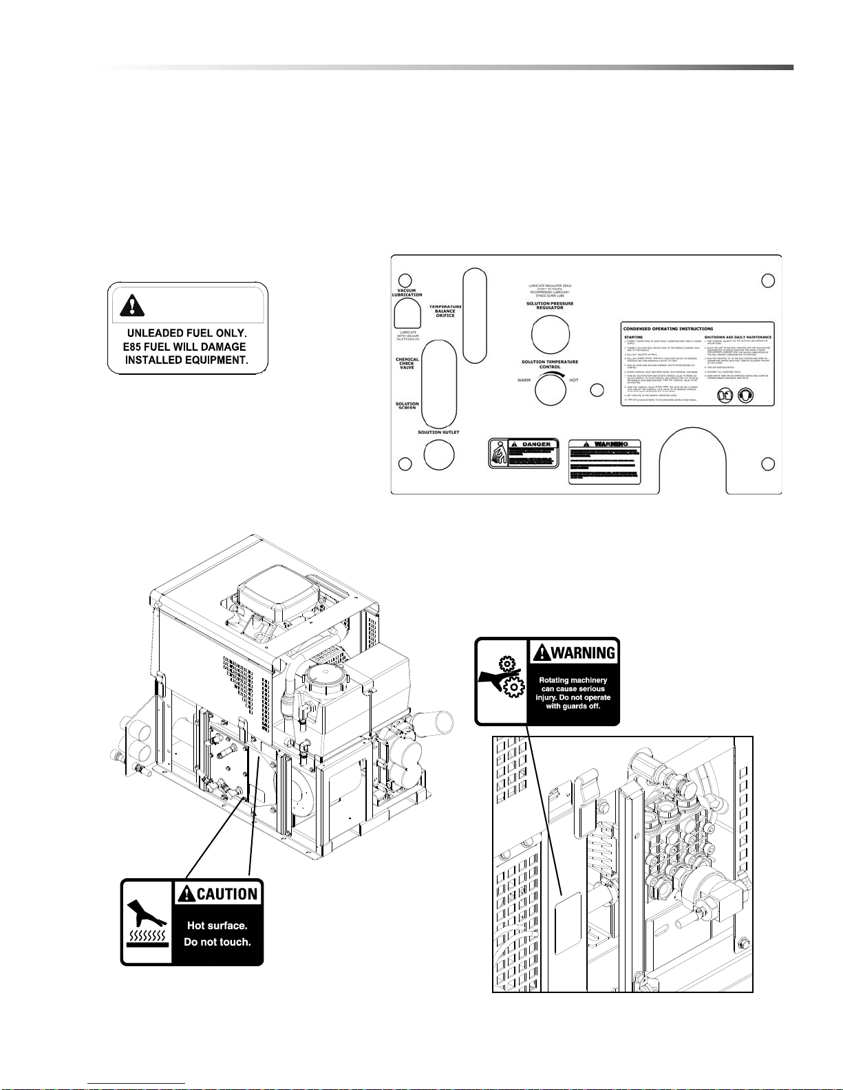
Safety Labels
The following WARNING LABELS are found on your cleaning unit. These labels point out important Warnings and
Cautions which should be followed at all times. Failure to follow warnings and cautions could result in fatality,
personal injury to yourself and/or others, or property damage. Follow these instructions carefully! DO NOT remove
these labels.
NOTE: If at any time the labels become illegible, promptly replace them.
Safety
86313050 LEGEND GT
Warning Label
P/N 86186520
Caution Label
P/N 86186530
Lower Front Panel Decal
with warning labels
P/N 86309420
Caution Label
P/N 86352580
Installation on vehicle fuel door.
CAUTION

10
Installation
Dealer Responsibility
Your distributor from whom you purchased this mobile
cleaning unit is responsible for correct installation of
this machine. The dealer is also responsible for initial
training of your operators and maintenance personnel
in proper operation and maintenance of this unit.
Vehicle Requirements
1. The unit should NOT be mounted in any motor
vehicle of less than 1/2 ton capacityor 3/4 ton if
equipped with one or more auxiliary fresh water
tanks.
DO NOT exceed the vehicle’s axle weight limit.
Include the console, full tanks, accessories, and
operators in calculations.
2. If mounting in a trailer, make certain that trailer is
rated for the total weight of UNIT AND TRAILER.
Electric or hydraulic brakes should be provided,
and a strict compliance with any State and Federal
vehicle laws must be maintained.
3. The vehicle tires should have a load rating above
the combined vehicle and unit weight.
4. We do not recommend using flooring materials that
absorb water. This could result in rust and
corrosion of the vehicle floor.
5. Padding under rubber floor mats should be
removed before installing this unit.
6. We highly recommend using a drip tray under
console (Part #86050370, or Part # 86050380 for
units mounted on a water tank).
7. If using a trailer, console should be positioned so
that it balances properly with respect to axle. Ten
percent (10%) of the overall unit weight, should be
on tongue.
Example: If loaded trailer weight is 2,000 lbs.,
tongue weight needs to be a minimum of 200 lbs.
to tow properly.
Lifting Unit Onto Vehicle
Since console weighs approximately 600 lbs. pounds,
(690 lbs. if mounted on water tank) we recommend
using a forklift to lift unit onto vehicle. Position forks
under unit from front and make CERTAIN that forks are
spread to insert into frame slots.
Positioning Unit In Vehicle
Because vehicles vary in size and openings, individuals
have their own preference as to where they want their
units installed. We strongly recommend a side door
installation for this and DO NOT recommend a rear
door installation.
1. Enough space should be provided to assure
adequate engine ventilation and room for service
and maintenance.
2. The unit with waste tank and accessories must
NOT exceed vehicle's axle weight limit. An empty
60 gallon waste tank and console weighs 810 lbs
(900 lbs. if mounted on water tank).
3. DO NOT position the console closer than 12" from
bottom of driver and passenger seats.
NOTE: For individuals who wish to make an
engineering layout prior to positioning unit, refer to
"Dimensional Data" illustrations for waste tank and
console dimensions.
4. Be sure to consider all accessories and their
required space prior to positioning the console and
waste tank.
86313050 LEGEND GT

11
Installation
Bolting Down Unit And Waste Tank
NOTE: When positioning waste tank with respect to
console, hook up the vacuum hose to waste tank.
This will ensure that waste tank is positioned
correctly. Proceed once unit and waste tank are
positioned in vehicle in desired location.
Before drilling any mounting holes in vehicle floor,
make certain that when drilling, you will not do any
damage to fuel tank, fuel lines, or any vital
component which might affect operation or safety
of vehicle.
1. Using console and waste tank mounting holes as a
template, drill six 13/32" diameter holes for
mounting console and six more 13/32" diameter
holes for mounting waste tank.
2. Using installation hardware kit:
a. Insert six 3/8-16 x 2" hex head cap screws with
flat washers through mounting holes in console,
and six 3/8-16 x 2" hex head cap screws with flat
washers through mounting holes in waste tank.
b. Install mounting plates underneath vehicle floor.
c. Screw 3/8-16 hex head locknuts on mounting
screws and tighten them until console and waste
tank are firmly secured to vehicle floor.
Electrical Wiring
Ensure all electrical wiring and battery cables are free
from contact with any metal edge. Engine vibration
could cause metal edge to cut wiring and possibly
result in a fire. Be aware of where battery cables are
run.
86313050 LEGEND GT
12
Installation
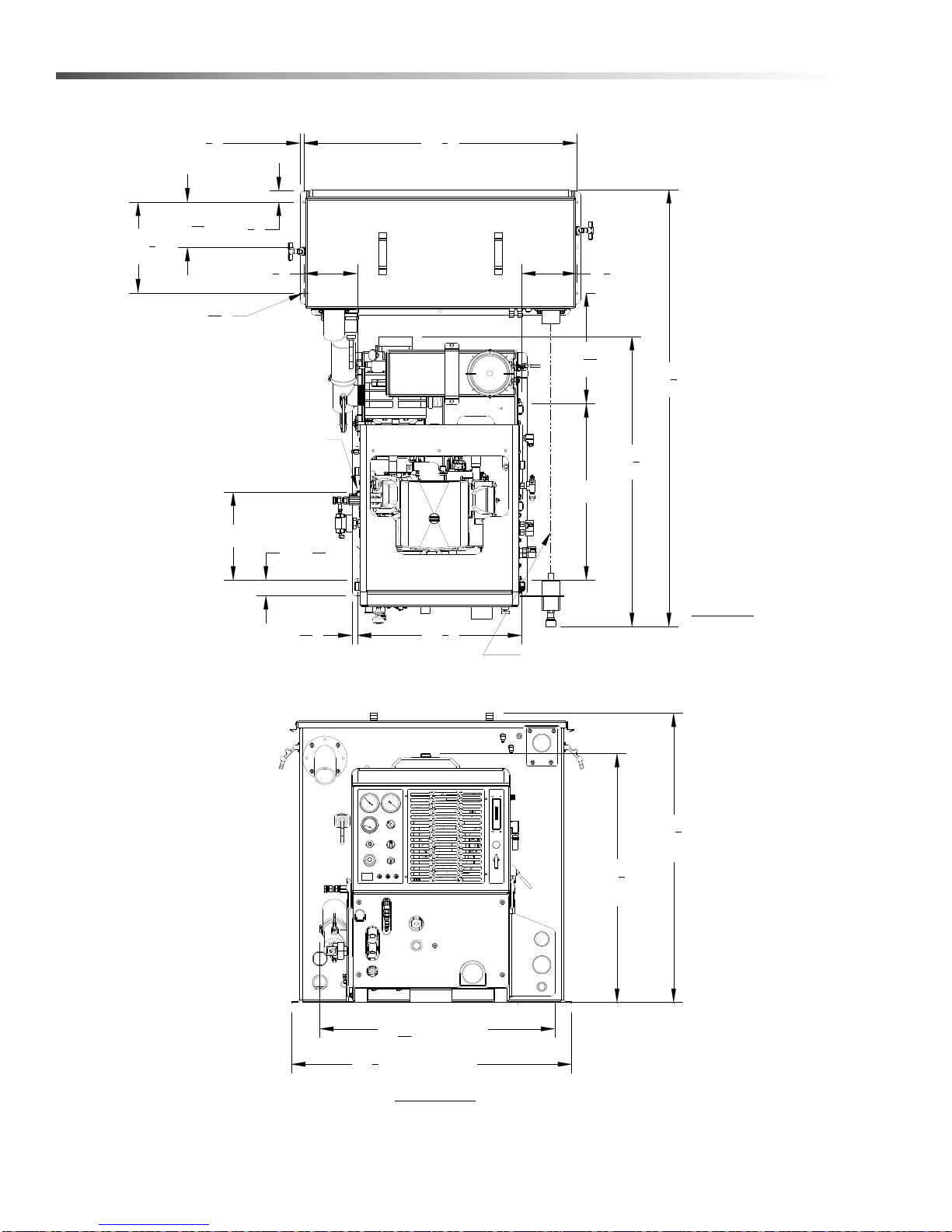
Layout with 60 Gallon Waste Tank
391
2"
337
8"
CONSOLE
393
8"
WASTE TANK
381
8" WASTE TANK
3131
32" CONSOLE
223
8"
6X Ø7/16" X 5/8" SLOT
371
8"
2X 11
2"
2X 63
16"
2X 123
8"
2X 2 3
32"
2X 12"
2X 24"
591
2"
6X Ø13
32"
TOP VIEW
FRONT VIEW
AND WASTE TANK ARE ALIGNED
ENSURE THAT VAC INLETS ON CONSOLE
1
2"
11
16"
71
4"
15 3
32"
71
2"
86313050 LEGEND GT

13
Installation
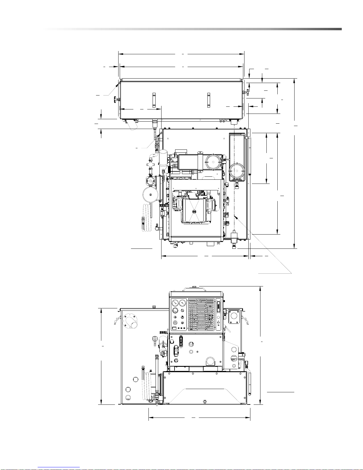
Layout with 60 Gallon Waste Tank & Optional Auxiliary Water Tank
6713
16"
LENGTH
383
8"
WASTE
TANK
AUXILIARY WATER TANK
FRONT VIEW
TOP VIEW
WASTE TANK
CONSOLE
381
8"
AND WASTE TANK ARE ALIGNED
ENSURE THAT VAC INLETS ON CONSOLE
2X 4013
32"
6X Ø13
32"
2X 123
8"
2X 63
16"
2X 111
16"
1
2"371
8"
11
16"
37
8" MIN.
6X Ø3
8"
3425
32"
2X 203
16"
471
8"
OVERALL
HEIGHT
4017
32"
721
32"
49
16"
721
32"
27
32"
86313050 LEGEND GT

14
Installation
Layout with 100 Gallon Waste Tank
9X Ø7/16" X 5/8" SLOT
191
4"
71
2"
153
32"
2X 123
8"
2X 12"
591
2"
LENGTH
ENSURE THAT VAC INLETS ON CONSOLE
AND WASTE TANK ARE ALIGNED
223
8"
11
16"
2X 6"
2X 111
16"
2X 63
16"
491
8"
1
2"
6X Ø13
32"
TOP VIEW
CONSOLE
WASTE TANK
333
8"
CONSOLE
HEIGHT
501
8"
FRONT VIEW
383
8"
WASTE
TANK
3131
32"
2X 24"
431
32"
86313050 LEGEND GT
15
Installation
Layout with 100 Gallon Waste Tank & Optional Auxiliary Water Tank
2X 12
3
8
"
2X 40
13
32
"
67
13
16
"
LENGTH
ENSURE THAT VAC INLETS ON CONSOLE
AND WASTE TANK ARE ALIGNED
34
25
32
"
11
16
"
2X 20
3
16
"
2X 1
11
16
"
2X 6
3
16
"
49
1
8
"
1
2
"
50
1
8
"
6X Ø
3
8
"
3
31
32
" MIN.
6X Ø
13
32
"
TOP VIEW
CONSOLE
AUXILIARY WATER TANK
WASTE TANK
47
1
8
"
OVERALL
HEIGHT
40
17
32
"
FRONT VIEW
38
3
8
"
WASTE
TANK
16
9
16
"2
7
32
"
7
21
32
"
86313050 LEGEND GT

16
Installation
Waste Tank To Console Connection
NOTE: Before connecting any hoses to the waste
tanks, make certain the hose clamps are on each
hose.
1. Connect the section of 2-7/8" I.D. internal vac hose
between the 2-7/8" dia. vac outlet tube on the
waste tank and the vacuum pump relief valve on
the console. It may be necessary to cut this hose
to fit. Tighten the hose clamps.
2. Connect the 2" I.D. waste removal hose to the 2"
dia. tube at the bottom corner of the waste tank.
Cut to desired length. Install brass ball valve on
other end.
3. Connect 2-1/2" I.D. hose between waste tank
vacuum inlet (upper right of waste tank) and
vacuum inlet on lower side panel of console.
4. Connect the 3/16" blue hose from the water box to
the lower flare fitting (angled downward) on the
waste tank.
5. Run the 5/8" water box overflow hose through the
van floor. Prior to drilling through the van floor,
ensure that no damage will occur in drilling area.
Ensure that you are in compliance with all local
environmental laws.
6. Connect the console engine shut-off cord to the
waste tank level sensor cord.
7. Connect the 3/16" blue hose from the solution
temperature control valve to the other flare fitting
(angled downward) on the waste tank.
Fire Extinguisher
We recommend that a fire extinguisher, preferably
rated for A, B, & C type fires, be installed inside the
vehicle.
Fuel Pump Assembly Installation
Before drilling the fuel line holes in the vehicle
floor, make certain that when drilling you will not do
any damage to the fuel tank(s), fuel lines, brake
lines, heat shields, or any other vital component
which might affect the operation or safety of the
vehicle.
Do not mount this assembly, any hoses or compo-
nents near the catalytic converter, exhaust, or any
areas of high temperature. Avoid any contact with
moving parts, areas of high temperature, brake
lines, fuel lines, muffler, catalytic converter, or
sharp objects.
1. Determine the position where the fuel pump
assembly will be mounted. Check to ensure that
the power cord length will support the mounting
location. The pump should be mounted as low as
possible and still be protected by the frame from
road hazards. Mount the fuel pump with the
discharge side of the pump higher than the
suction side to eliminate the possibility of
trapped air in the pump. Additional mounting
holes are provided to allow for different mounting
options.
2. Drill a 5/8" (.625) diameter hole in the vehicle floor
for routing the fuel pump power cord to the truck-
mount console. Check to ensure that the cord
length will support the location of the hole.
3. Route the power cord and install the hole grommet.
4. Do not connect the power cord to the truckmount
console wiring harness until installation is
complete.
86313050 LEGEND GT

17
Installation
Van Bulkhead Installation
1. Select a location on the vehicle floor to drill the hole for the bulkhead adapter. This location should be situated
in a position that eliminates the possibility of fuel line contact by either the operator(s) or accessories during the
working hours or maintenance periods. Make certain that the supplied hoses will reach the location and work
with the configuration you choose.
2. Drill a 5/8" (.625) diameter hole through the vehicle floor at the installation point chosen for the bulkhead.
3. Install the 1/8 NPT bulkhead adapter by inserting the adapter and tightening the nut on the opposite side of the
van floor.
4. Attach the 1/8 NPT x 1/4 Hosebarb 90 degree elbow to the bulkhead inside the van to connect the fuel system
to the console.
5. Attach the 1/4" fuel hose from the console to the 1/4” Hosebarb 90 degree elbow on the bulkhead.
TO CONSOLE
USE AS NEEDED
BULKHEAD ADAPTER
BULKHEAD NUT
HOSEBARB ELBOW
HOSEBARB ELBOW
HOSE MOUNTING CLAMPS
FUEL HOSE
HOSE CLAMP
VEHICLE FLOOR
5/8" DIA HOLE
LOCTITE
BYPASS FUEL FILTER
FUEL HOSE FROM
BULKHEAD GASKET
BULKHEAD GASKET
86313050 LEGEND GT

18
Installation
Fuel Supply & Return Line Installation
(Underneath Van)
1. Attach the 1/8 NPT x 5/16 Hosebarb 90 degree elbow to the bulkhead adapter underneath the van to be used
for the fuel supply line.
2. Cut to length the 6' piece of 5/16" 50 PSI fuel hose used for the supply line from:
a. Bulkhead adapter to the outlet side of the bypass fuel filter.
b. Inlet side of the bypass fuel filter to the discharge side of the fuel pump.
c. Inlet side of the fuel pump to the outlet side of the inline fuel filter.
3. Cut to length the 6' piece of 1/4" fuel line to connect the bypass fuel filter with the fuel tank return using the
appropriate fuel tap kit.
4. Check all hose clamps for tightness.
NOTE: Fuel tap kit installation instructions are found with appropriate fuel tap kit. Refer to Fuel Tap Kit
Information Sheet (8.634-994.0)
CHECK VALVE
5/16" SUPPLY HOSE
BYPASS FUEL FILTER
HOSE MOUNTING CLAMP
FRONT OF VAN
BULKHEAD CONNECTOR
BUSHING
ELECTRICAL CORD
PUMP ASSEMBLY
ELECTRICAL FUEL
USE AS NEEDED
5/16" SUPPLY HOSE
5/16" SUPPLY HOSE
FUEL SUPPLY
RETURN TO VEHICLE
FROM VEHICLE
FUEL SUPPLY
FUEL FLOW
FUEL FILTER
1/4" RETURN HOSE
86313050 LEGEND GT
Other manuals for LEGEND GT
1
Table of contents
Other Prochem Water System manuals

Popular Water System manuals by other brands

sylber
sylber SN 150/1 T Installer, technical assistance centre and user manual

Kenmore
Kenmore 625.347001 owner's manual

Pentair
Pentair SIATA V132 SFE-EV VIRIDION user manual

Reo-Pure
Reo-Pure 90403 Installation, operation & maintenance manual

Ace
Ace ACE.BOIL manual

EXTREME HEAT SOLAR
EXTREME HEAT SOLAR Geyser instruction manual

Pura
Pura QCUF Installation & operation manual

Irrigatia
Irrigatia SOL-K12 Instructions for use

AquaLiv
AquaLiv A305 Usage & installation instructions

Pelican
Pelican Advantage Series owner's manual

Watts
Watts FEBCO 765 INSTRUCTION, INSTALLATION, MAINTENANCE AND REPAIR MANUAL

BWT
BWT STARDECK INEO Installation and maintenance instructions


