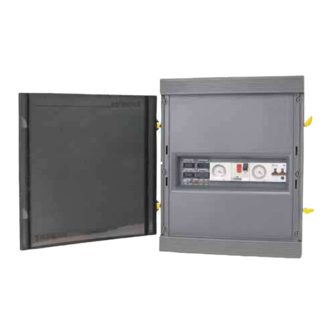
Procopi SWIMLINE CFB Series User manual

2010/07 - Indice de révision : E - Code : 0032502
SWIMLINE
CFB / CFP
Coffrets de commande pour filtrations de piscines
Control panels for swimming pool filtration systems
Steuerkästen für Filteranlagen für Schwimmbecken
Cajas de mando para filtración piscina
NOTICE D’INSTALLATION ET CONSEILS D’UTILISATION
A lire attentivement et à conserver pour consultation ultérieure.
INSTRUCTIONS FOR INSTALLATION AND USE
Read these instructions carefully and keep for future reference.
MONTAGEANLEITUNG UND ANWENDUNGSHINWEISE
Bitte lesen Sie diese Anleitung aufmerksam durch, und bewahren Sie sie sorgfältig auf.
INSTRUCCIONES DE MONTAJE Y EMPLEO
Lea con atención estas instrucciones y guárdelas para futuras consultas.

2/12
2010/07 - Indice de révision : E - Code : 0032502
RECOMMANDATIONS IMPORTANTES
- L’installation d’un coffret électrique doit être réalisée dans les règles de l’art, suivant les normes en vigueur.
- L’alimentation électrique du coffret devra être protégée en amont par un disjoncteur différentiel de 30 mA
- Avant toute intervention nécessitant la dépose de la façe avant, s’assurer que l’alimentation électrique est coupée
en amont du coffret.
- Le coffret doit être complété par un disjoncteur approprié à la puissance du moteur qu’il doit alimenter.
L’installation d’un disjoncteur trop puissant peut entraîner la détérioration du moteur électrique.
- Le fusible doit être remplacé impérativement par un fusible de mêmes caractéristiques.
UTILISATION DU COMMUTATEUR “FILTRATION”
Position “Manuel” ..: Fonctionnement continu de la filtration.
Position “Auto ........: Fonctionnement de la filtration suivant la programmation de l’horloge.
Position “Arrêt” ......: Arrêt permanent de la filtration.
IMPORTANT RECOMMENDATIONS
- The control panel must be installed in accordance with the rules of the art and the standards applicable in the country
of installation.
- The control panel power supply must be protected by a 30 mA differential circuit breaker at the top of the line.
- Make sure that the power supply has been disconnected upstream from the control panel before any intervention
requiring the removal of the front plate.
- The control panel must be equipped with a circuit breaker rated for the electrical power of the motor being supplied.
Use of a circuit breaker that is too powerful can cause damage to the electrical motor.
- If the fuse needs to be replaced, use a fuse with the same rating.
USE OF THE "FILTER" SWITCH
"Manual" position....: Continuous filtration mode
"Auto" position ........: Timer programmed filtration mode
"Stop" position........: Permanent stop position
WICHTIGE HINWEISE
Der Steuerkasten muss nach den geltenden Richtlinien von einem Fachmann installiert werden.
Zum Schutz der Stromversorgung des Steuerkastens muss an der Zufuhrleitung ein FI-Schalter 30 mA montiert werden.
Vor jeder Maßnahme, die die Entfernung der Frontplatte erfordert, muss sicher gestellt werden, das die Stromversorgung
an der Zufuhrleitung unterbrochen ist.
Der Steuerkasten muss zusätzlich mit einem für den Motor, der über den Steuerkasten mit Strom versorgt wird,
geeigneten Unterbrecherkontakt ausgerüstet sein.
Wenn ein zu starker Unterbrecherkontakt montiert wird, kann der elektrische Motor beschädigt werden.
Wenn Sie die Sicherung ersetzen, müssen Sie ein Modell mit den gleichen technischen Merkmalen verwenden.
Verwendung des Schalters für den "FILTER"
Stellung "Manuell" : Dauerbetrieb des Filters
Position "Auto" . . . : Filterbetrieb nach Programmierung der Zeitschaltuhr
Position "Stop" . . . : Filter ständig auf "Stop"
RECOMENDACIONES IMPORTANTES
La instalación de la caja de mando debe ser realizada según las normas vigentes.
La alimentación de la caja de mando debe ser protegida por un disyuntor de 30 mA encima de la línea.
Antes de quitar la placa frontal asegurarse que la alimentación eléctrica ha sido cortada.
La caja de mando debe ser equipada con un disyuntor ajustado a la potencia del motor alimentado por la caja de mando.
Para sustituir el fusible ha de emplearse uno de las mísmas características.
EMPLEO DEL CONMUTADOR "FILTRACIÓN"
Posición "Manual" : Operación contínua de la filtración
Posición "Auto". . . : Funcionamiento de la filtración según la programación del reloj.
Posición "Paro". . . : Paro permanete de la filtración

3/12
2010/07 - Indice de révision : E - Code : 0032502
FIXATION MOUNTING
BEFESTIGUNG FIJACIÓN
Débloquer les 6 vis plastique et retirer la face avant
Loosen the 6 plastic screws and remove the front plate
Lösen Sie die 6 Plastikschrauben und entfernen Sie die Frontplatte
Debloquear los 6 tornillos plásticos y quitar la placa frontal
Retirer la vis de maintien de l’étrier de fixation
Remove the screw from the wall bracket
Entfernen Sie die Schraube an der Halterung
Quitar el tornillo de soporte de la sujeción
Utiliser l’étrier comme gabarit de perçage
Use the bracket as a drilling template
Verwenden Sie die Halterung als Bohrschablone
La sujeción sirve para plantilla de taladro
Fixer l’étrier au mur à l’aide des chevilles et vis fournies
Using the bushings and screws provided, fix the bracket to the wall
Befestigen Sie die Halterung mit den mit gelieferten Dübeln und Schrauben an der Wand
Fijar en el muro la sujeción con los tacos y tornillos suministrados
Accrocher le coffret sur l’étrier et remettre la vis en place
Mount the control panel on the bracket and replace the screw
Befestigen Sie d. Steuerk. an der Halt. u. setzen Sie die Schraube wieder ein
Fijar la caja de mando en el soporte y insertar el tornillo de soporte.
Accrocher le disjoncteur-moteur sur le rail au-dessus du contacteur
Attach the motor circuit breaker to the rail above the contactor
Befestigen Sie den FI-Schalter Motor an der Schiene über dem Schütz
Fijar el disjuntor motor en el raile por encima del contactor
Remonter la face avant lorsque le câblage est terminé
Once wiring is complete, replace the front plate
Setzen Sie nach beendeter Verkabelung die Frontplatte wieder ein
Reinstalar la placa frontal después de haber terminado el cableado
Mettre en place les presse-étoupe et réaliser les connexions
Install the cable glands and carry out the wiring
Montieren Sie die Stopfbüchsen für und machen Sie die Anschlüsse
Montar las prensas estopas y hacer las conexiones
1
8
7
6
5
4
3
2

4/12
2010/07 - Indice de révision : E - Code : 0032502
REVERSIBILITÉ DE L’OUVERTURE REVERSIBLE OPENING
REVERSIBLES ÖFFNEN APERTURA REVERSIBLE
Retirer la porte de ses charnières
Remove the door from its hinges
Heben Sie die Tür aus den Scharnieren
Retirar la puerta de las charnelas
Intervertir et replacer les charnières et les verrous
Swap the position of the hinges and the locking plates
Vertauschen Sie die Scharniere mit den Verriegelungen
Sustituir la posición de las charnelas por la de las placas de cierre
1
3
Retirer les charnières et les verrous
Remove the hinges and the locking plates
Entfernen Sie die Scharniere und Verriegelung
Quitar las charnelas y las placas de cierre
2
Recliper la porte dans ses charnières
Clip the door back into its hinges
Setzen Sie die Türe wieder in die Scharniere
Insertar la puerta en las charnelas
4
Instructions pour le câblage
Les instructions ci-après concernent uniquement les connexions qui doivent être effectuées par l’installateur. Le câblage du coffret est déjà
réalisé lors de la fabrication et ne doit en aucun cas être modifié au risque de dégradations ou d’accidents.
Il est primordial d’utiliser des câbles de section suffisante en fonction de l’intensité qu’ils doivent véhiculer (particulièrement pour les projecteurs).
Vérifier également le serrage correct des connexions.
Un câble de section insuffisante ou une connexion mal serrée s’échauffe et peut provoquer un début d’incendie.
Wiring instructions
The following instructions are only applicable to connections that must be carried out by an installer. The control panel is pre-wired in the factory,
wiring should under no circumstances be modified, failure to observe this instruction could lead to material damage or accidents.
Due to the electrical loads to be transferred by the cables, it is absolutely necessary to use cables with correctly dimensioned cross sections (in
particular for underwater lights). Make sure that the connections are tight. Bad cable sections and poorly tightened connections may get hot and
cause a fire.
Hinweise für die Verkabelung
Die nachfolgenden Anweisungen gelten nur für die von einem Installateur ausgeführten Anschlussarbeiten. Die Verkabelung des Steuerkastens
erfolgt werkseitig und darf auf keinen Fall verändert werden. Gefahr der Beschädigung oder eines Unfalls.
Verwenden Sie nur Kabel mit passenden Querschnitten in Anbetracht der elektrischen Belastung der Kabel (v. a. bei Scheinwerfern). Achten Sie
auf fest sitzende Verbindungen.
Wenn die Kabelquerschnitte falsch sind und die Verbindungen nicht fest sitzen, können sie sich erhitzen und entzünden.
Instrucciones de cableado
Las instrucciones siguientes se refieren solamente a conexiones realizadas por un instalador. El cableado de la caja de mando ha sido realizado
en fábrica y no debe ser modificado en ningún caso. Riesgo de deterioración y de accidente.
El empleo de cables de sección suficiente es muy importante teniendo en cuenta la carga eléctrica considerable des los cables (sobre todo
para proyectores). Asegurarse también que las conexiones están bien apretadas.
Cables de sección insuficiente o una conexión mal apretada pueden calentarse y provocar un incendio.

5/12
2010/07 - Indice de révision : E - Code : 0032502
I O
N
T
L3
L2
L1
0
1
10 A
I O
N
T
L3
L2
L1
0
1
10 A
1 : Alimentation 380 V + Neutre + Terre
2 : Départ 380 V + Terre vers moteur
1: Power supply 380 V + Neutral + Earth
2: Outlet 380 V + Earth to the motor
1:
Spannungsversorgung 380 V + Neutral + Erde
2: Ausgang 380 V + Erde zum Motor
1: Alimentación 380 V + Neutro + Tierra
2: Salida 380 V + Tierra en el motor
1 : Alimentation 230 V + Terre
2 : Départ 230V + Terre vers moteur
Shunt entre N et L1
Shunt between N and L1
Ableitung zwischen N + 1
Derivación entre N y 1
1: Power supply 230 V + Earth
2: Outlet 230 V + Earth to the motor
1: Spannungsversorgung 230 V + Erde
2: Ausgang 230 V + Erde zum Motor
1: Alimentación 230 V + Tierra
2: Salida 230 V + Tierra en el motor
12
12
CÂBLAGE 380 V TRIPHASÉ WIRING 380 V THREE-PHASE
VERKABELUNG 380V DREIPHASIG CABLEADO 380 V TRIFÁSICO
CÂBLAGE 230 V MONOPHASÉ WIRING 230 V SINGLE-PHASE
VERKABELUNG 230V EINPHASIG CABLEADO 230 V MONOFÁSICO
SWIMLINE CFB-1

6
2010/07 - Indice de révision : E - Code : 0032502
I O
N
T
I O
L3
L2
L1
0
1
0
1
6.3 A
I O
N
T
I O
L3
L2
L1
0
1
0
1
6.3 A
1 : Alimentation 380 V + Neutre + Terre
2 : Départ 380 V + Terre vers moteur
3 : Départ 230 V + Terre vers surpresseur
1 : Power supply 380 V + Neutral + Earth
2 : Outlet 380 V + Earth to the motor
3 : Outlet 230 V + Earth to booster pump
1:
Spannungsversorgung 380 V + Neutral + Erde
2: Ausgang 380 V + Erde zum Motor
3: Ausgang 230 V + Erde zur Antriebsumpe
1: Alimentación 380 V + Neutro + Tierra
2: Salida 380 V + Tierra al motor
3: Salida 230 V + Tierra al sobrepresor
1 : Alimentation 230 V + Terre
2 : Départ 230 V + Terre vers moteur
3 : Départ 230 V + Terre vers surpresseur
1: Power supply 230 V + Earth
2: Outlet 230 V + Earth to the motor
3 : Outlet 230 V + Earth to booster pump
1: Spannungsversorgung 230 V + Erde
2: Ausgang 230 V + Erde zum Motor
3: Ausgang 230 V + Erde zur Antriebsumpe
1: Alimentación 230 V + Tierra
2: Salida 230 V + Tierra al motor
3: Salida 230 V + Tierra al sobrepresor
123
123
SWIMLINE CFB-1+BA
CÂBLAGE 230 V MONOPHASÉ WIRING 230 V SINGLE-PHASE
VERK ABELUNG 230V EINPHASIG CABLEADO 230 V MONOFÁSICO
Shunt entre N et L1
Shunt between N and L1
Ableitung zwischen N + 1
Derivación entre N y 1
CÂBLAGE 380 V TRIPHASÉ WIRING 380 V THREE-PHASE
VERKABELUNG 380V DREIPHASIG CABLEADO 380 V TRIFÁSICO

7/12
2010/07 - Indice de révision : E - Code : 0032502
I O
N
T
L3
L2
L1
0
1
12 V0
I O
N
T
L3
L2
L1
0
1
12 V0
1 : Alimentation 380 V + Neutre + Terre
2 : Départ 380 V + Terre vers moteur
3 : Départ 12 V vers projecteurs
1 : Power supply 380 V + Neutral + Earth
2 : Outlet 380 V + Earth to the motor
3 : Outlet 12 V to the underwater lights
1:
Spannungsversorgung 380 V + Neutral + Erde
2: Ausgang 380 V + Erde zum Motor
3: Ausgang 12 V zu den Scheinwerfern
1: Alimentación 380 V + Neutro + Tierra
2: Salida 380 V + Tierra al motor
3: Salida 12 V a los proyectores
1 : Alimentation 230 V + Terre
2 : Départ 230 V + Terre vers moteur
3 : Départ 12 V vers projecteurs:
1: Power supply 230 V + Earth
2: Outlet 230 V + Earth to the motor
3: Outlet 12 V to the underwater lights
1: Spannungsversorgung 230 V + Erde
2: Ausgang 230 V + Erde zum Motor
3: Ausgang 12 V zu den Scheinwerfern
1: Alimentación 230 V + Tierra
2: Salida 230 V + Tierra al motor
3: Salida 12 V a los proyectores
12
123
CÂBLAGE 230 V MONOPHASÉ WIRING 230 V SINGLE-PHASE
VERK ABELUNG 230V EINPHASIG CABLEADO 230 V MONOFÁSICO
CÂBLAGE 380 V TRIPHASÉ WIRING 380 V THREE-PHASE
VERKABELUNG 380V DREIPHASIG CABLEADO 380 V TRIFÁSICO
SWIMLINE CFP-60
Shunt entre N et L1
Shunt between N and L1
Ableitung zwischen N + 1
Derivación entre N y 1
3

8/12
2010/07 - Indice de révision : E - Code : 0032502
I O
N
T
L3
L2
L1
0
1
12 V0 12 V0
I O
N
T
L3
L2
L1
0
1
12 V0 12 V0
1 : Alimentation 380 V + Neutre + Terre
2 : Départ 380 V + Terre vers moteur
3 : Départ 12 V vers projecteurs
1 : Power supply 380 V + Neutral + Earth
2 : Outlet 380 V + Earth to the motor
3 : Outlet 12 V to the underwater lights
1:
Spannungsversorgung 380 V + Neutral + Erde
2: Ausgang 380 V + Erde zum Motor
3: Ausgang 12 V zu den Scheinwerfern
1: Alimentación 380 V + Neutro + Tierra
2: Salida 380 V + Tierra al motor
3: Salida 12 V a los proyectores
1 : Alimentation 230 V + Terre
2 : Départ 230 V + Terre vers moteur
3 : Départ 12 V vers projecteurs:
1: Power supply 230 V + Earth
2: Outlet 230 V + Earth to the motor
3: Outlet 12 V to the underwater lights
1: Spannungsversorgung 230 V + Erde
2: Ausgang 230 V + Erde zum Motor
3: Ausgang 12 V zu den Scheinwerfern
1: Alimentación 230 V + Tierra
2: Salida 230 V + Tierra al motor
3: Salida 12 V a los proyectores
12
CÂBLAGE 230 V MONOPHASÉ WIRING 230 V SINGLE-PHASE
VERK ABELUNG 230V EINPHASIG CABLEADO 230 V MONOFÁSICO
CÂBLAGE 380 V TRIPHASÉ WIRING 380 V THREE-PHASE
VERKABELUNG 380V DREIPHASIG CABLEADO 380 V TRIFÁSICO
SWIMLINE CFP-105
Shunt entre N et L1
Shunt between N and L1
Ableitung zwischen N + 1
Derivación entre N y 1
33
1233

9/12
2010/07 - Indice de révision : E - Code : 0032502
I O
N
T
L3
L2
L1
0
1
10 A
12 V0
32 A
12 V0
32 A
I O
N
T
L3
L2
L1
0
1
10 A
12 V0
32 A
12 V0
32 A
1 : Alimentation 380 V + Neutre + Terre
2 : Départ 380 V + Terre vers moteur
3 : Départ 12 V vers projecteur(s)
1: Power supply 380 V + Neutral + Earth
2: Outlet 380 V + Earth to the motor
3: Outlet 12 V to the underwater lights
1: Spannungsversorgung 380 V + Neutral + Erde
2: Ausgang 380 V + Erde zum Motor
3: Ausgang 12 V zu den Scheinwerfern
1: Alimentación 380 V + Neutro + Tierra
2: Salida 380 V + Tierra al motor
3: Salida 12 V a los proyectores
1 : Alimentation 230 V + Terre
2 : Départ 230 V + Terre vers moteur
3 : Départ 12 V vers projecteur(s)
1: Power supply 230 V + Earth
2: Electric outlet 230 V + Earth to the motor
3: Outlet 12 V to the underwater lights
1: Stromversorgung 230 V + Erde
2: Ausgang 230 V + Erde zum Motor
3: Ausgang 12 V zu den Scheinwerfern
1: Alimentación 230 V + Tierra
2: Salida 230 V + Tierra en el motor
3: Salida 12 a los proyectores
1 2
33
12
SWIMLINE CFP-315 / CFP-630
CÂBLAGE 380 V TRIPHASÉ WIRING 380 V THREE-PHASE
VERKABELUNG 380V DREIPHASIG CABLEADO 380 V TRIFÁSICO
CÂBLAGE 230 V MONOPHASÉ WIRING 230 V SINGLE-PHASE
VERKABELUNG 230V EINPHASIG CABLEADO 230 V MONOFÁSICO
Shunt entre N et L1
Shunt between N and L1
Ableitung zwischen N + 1
Derivación entre N y 1
CFP-630
CFP-630
33

10/12
2010/07 - Indice de révision : E - Code : 0032502
I O
N
T
I O
L3
L2
L1
0
1
0
1
6.3/10A
12 V0
32 A
12 V0
32 A
SWIMLINE CFP-315+BA / CFP-630+BA
I O
N
T
I O
L3
L2
L1
0
1
0
1
6.3/10A
12 V0
32 A
12 V0
32 A
1 : Alimentation 380 V + Neutre + Terre
2 : Départ 380 V + Terre vers moteur
3 : Départ 230 V + Terre vers surpresseur
4 : Départ 12 V vers projecteur(s)
1 : Power supply 380 V + Neutral + Earth
2 : Outlet 380 V + Earth to the motor
3 : Outlet 230 V + Earth to booster pump
4 : Outlet 12 V to the underwater lights
1:
Spannungsversorgung 380 V + Neutral + Erde
2: Ausgang 380 V + Erde zum Motor
3: Ausgang 230 V + Erde zur Antriebsumpe
4: Ausgang 12 V zu den Scheinwerfern
1: Alimentación 380 V + Neutro + Tierra
2: Salida 380 V + Tierra al motor
3: Salida 230 V + Tierra al sobrepresor
4: Salida 12 V a los proyectores
1 : Alimentation 230 V + Terre
2 : Départ 230 V + Terre vers moteur
3 : Départ 230 V + Terre vers surpresseur
4 : Départ 12 V vers projecteur(s)
1: Power supply 230 V + Earth
2: Outlet 230 V + Earth to the motor
3:
Outlet 230 V + Earth to the booster pump
4: Outlet 12 V to the underwater lights
1: Spannungsversorgung 230 V + Erde
2: Ausgang 230 V + Erde zum Motor
3:
Ausgang 230 V + Erde zur Antriebspumpe
4: Ausgang 12 V zu den Scheinwerfern
1: Alimentación 230 V + Tierra
2: Salida 230 V + Tierra al motor
3: Salida 230 V + Tierra al sobrepresor
4: Salida 12 V a los proyectores
123
4
123
4
CÂBLAGE 230 V MONOPHASÉ WIRING 230 V SINGLE-PHASE
VERK ABELUNG 230V EINPHASIG CABLEADO 230 V MONOFÁSICO
Shunt entre N et L1
Shunt between N and L1
Ableitung zwischen N + 1
Derivación entre N y 1
CÂBLAGE 380 V TRIPHASÉ WIRING 380 V THREE-PHASE
VERKABELUNG 380V DREIPHASIG CABLEADO 380 V TRIFÁSICO
CFP-630
CFP-630
4
4

11/12
2010/07 - Indice de révision : E - Code : 0032502
ANWENDUNGSHINWEISE
a) Heben Sie den Klarsichtdeckel an, um den Drehschalter zugänglich zu machen.
b) Programmieren Sie die gewünschte Zeit, indem Sie die Segmente nach außen positionieren. 1 Segment entspricht 30 Minuten auf der
Scheibe für die Tageszeitprogrammierung
Beispiel: Für eine Programmierung von 13 bis 16 Uhr müssen 6 Segmente auf der Scheibe mit 24 Stunden nach außen positioniert werden.
c) – Drehen Sie die Scheibe in Pfeilrichtung, um die Zeitschaltuhr einzustellen. Für die Feineinstellung muss nur der Minutenzeiger bewegt
werden. Der kleine Zeiger ist auf die innere Scheibe gedruckt. Die Stunden werden ebenfalls gegenüber der Markierung eingestellt (s.
Zeichnung oben).
d) Achten Sie darauf, dass der Wählschalter oben rechts auf folgender Position steht
WICHTIG
Die Scheibe darf nicht im Gegenuhrzeigersinn gedreht werden.
MODE D'EMPLOI
Programmation :
a) - Soulever la fenêtre transparente pour accéder à la molette de réglage de l'horloge.
b) - Programmer les temps de fonctionnement désirés en poussant vers l’extérieur les segments de cadran de la couronne. Chaque segment
représente 30 minutes.
Exemple : Pour une programmation de 13 à 16 heures, il faut pousser vers l'extérieur 6 segments sur le cadran de 24 heures.
c) -
La mise à l'heure de l'horloge s'effectue en tournant le cadran dans le sens de la flèche. Pour affiner le réglage, tourner uniquement l’aiguille
des minutes
. La petite aiguille de l’horloge est imprimée sur le cadran intérieur et l’heure vient également se positionner en face de l'ergot de
contact (voir croquis ci-dessus).
d) Veiller à ce que le bouton de sélection en haut et à droite de l’horloge soit bien sur la position
ATTENTION :
Ne jamais tourner le cadran dans le sens contraire des aiguilles d'une montre.
Connexion asservissement
Slaving connection
Geräteanschluss
Conexión equipamiento
Alimentation du moteur de l’horloge
Power supply to the time switch motor
Spannungsversorgung Motor Zeitschaltuhr
Alimentación del motor del reloj
Molette de mise à l’heure
Thumbwheel switch
Daumenradschalter
Conmutador rotativo
Segments de programmation
Programming segment
Programmiersegment
Segmento de programación
Ergot de contact
Contact tab
Markierung
Pestaña
Bouton de sélection
Selector switch
Wählschalter
Botón de selección
INSTRUCTIONS FOR USE
Programming:
a) - Raise the transparent cover to access the thumbwheel.
b) - Move the segments of the time setting disk towards the outside to program the desired operating times. Each segment represents 30
minutes.
Example : Move 6 neighbouring segments of the 24 hour time setting disk towards the outside to program a 3 hour filtration period.
c) - Turn the time setting disk in the direction of the arrow to set the time.. For fine setting, only turn the minute hand.
The small hand of the timer is printed on the inside of the time setting disk. The hour will also be set opposite the contact tab (arrow)(see
drawing above).
d) - Make sure that the selector button on the top right hand side is set to the position
ATTENTION :
Do not turn the time setting disk anti-clockwise.
1 2 3 4 5
1
1
M
INSTRUCCIONES DE EMPLEO
a) Levantar la cubierta transparente para tener acceso al conmutador rotativo.
b) El tiempo de funcionamiento deseado se programa moviendo hacia el exterior los segmentos del disco selector. Cada segmento equivale a
30 minutos.
Ejemplo: Mover hacia el exterior 6 segmentos en el disco de 24 horas para una programación de 13.00 a 16.00 horas.
c) Girar el disco selector en sentido indicado por la flecha para reglar el reloj. Girar solamente las agujas de minutos para un ajuste de
precisión. La aguja pequeña del reloj está en el disco interior. La hora se regla también frente a la pestaña (ver dibujo de arriba).
d) Asegurarse que el botón de selección en la parte superior derecha del reloj está en la posición
ATENCIÓN:
No girar nunca el disco en sentido contrario a las agujas del reloj.
CFB-1 - CFP-60 - CFP-105 - CFP-315 - CFP-630
CFB-1+BA - CFP-315+BA - CFP-630+BA
FONCTIONNEMENT DE L’HORLOGE TIMER OPERATION
FUNKTIONSWEISE DER ZEITSCHALTUHR FUNCIONAMIENTO DEL RELOJ

12/12
2010/07 - Indice de révision : E - Code : 0032502
13
L3L2L1N
W
U
S1
KM1
A1
A2
1
4
M
M
ON
OFF
A
A
T
KM 1
DISJ-1 5
135
246
246
M
F1-6Amp
F1
6 Amp (FP315)
10 Amp (FP630)
F1
6 Amp (FP315)
10 Amp (FP630)
TR-55W
TR-100VA
15A
TR-630VA
32A 32A
TR-315VA
32A
CFP60 CFP105 CFP630CFP315
13
L3L2L1N
W
U
S1
KM1
A1
A2
1
4
M
M
A
A
T
KM 1
DISJ-1 5
135
246
246
M
F1-2Amp
F1-2Amp
SWIMLINE CFB-1
SCHÉMA ÉLECTRIQUE WIRING DIAGRAM
SCHALTPLAN DIAGRAMA ELÉCTRICO
SWIMLINE CFP-315 / CFP-630
13
L3
L2
L1
N
S1
KM2
H2
A1
A2
MA
T
KM 2
DISJ-2
1
1
13
14
35
24
24
4
6
M
F1-2 Amp
F1-2Amp
SUPPLEMENT BA EXTRA BA
ZUSATZ BA SUPLEMENTO BA
S. A au capital de 6 000 000 €- R.C.S/Rennes B 333 263 846 000 37
This manual suits for next models
9
Other Procopi Control Panel manuals
