Procopi Wooden Pools Rectangular Pro User manual

Installation instructions
To be read carefully and kept for future reference
Wooden Pools
WOODEN POOLS
RECTANGULAR PRO
PROCOPI
Les Landes d’Apigné
B.P.45328
35650 LE RHEU Cedex
FRANCE
Notice Piscine bois rectangle pro GF6/2012
FR-GB - Indice de révision : B - Code : 97289999
46
>> RECTANGULAR POOLS
>>
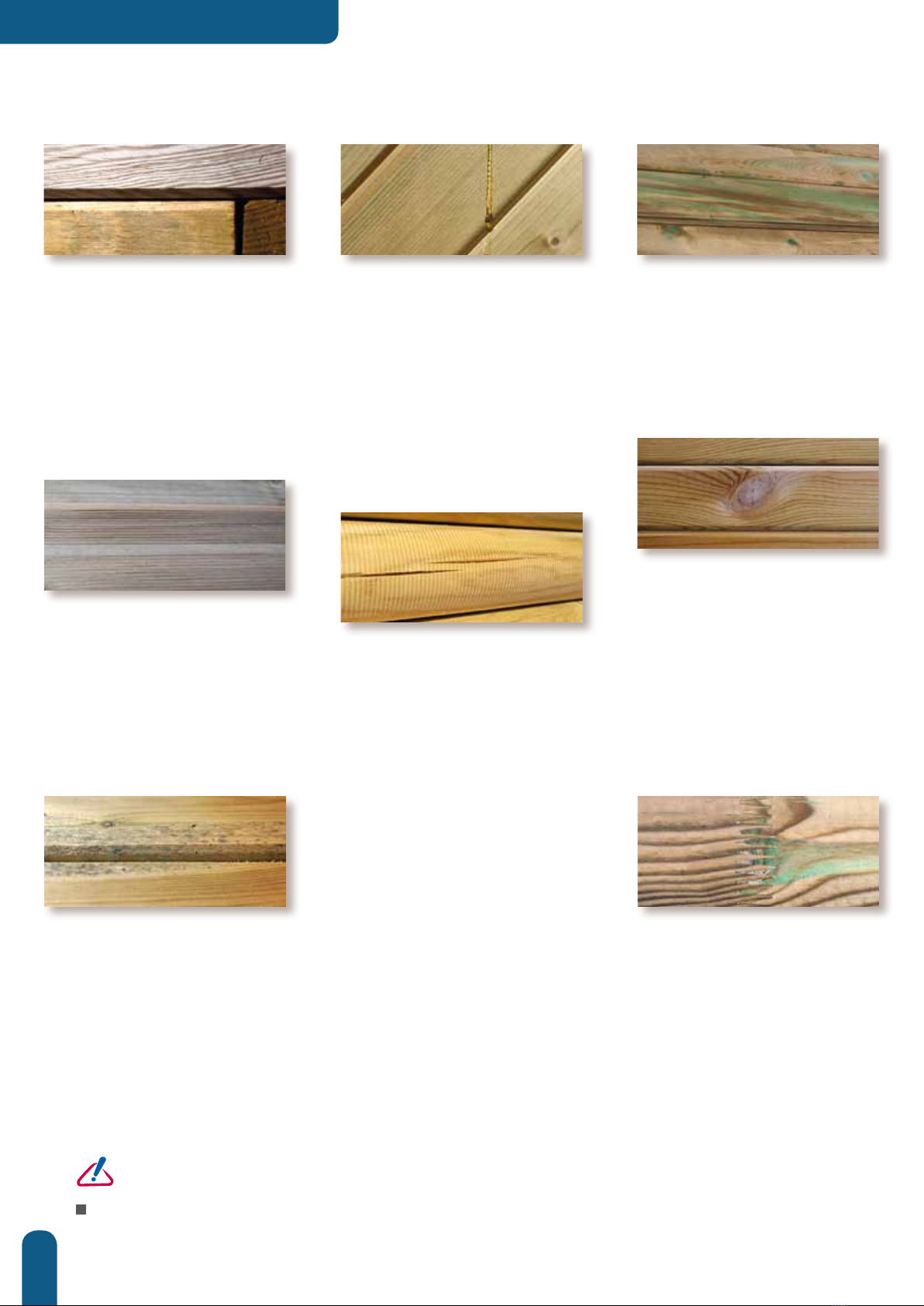
RESIN BEADS
When resinous wood species
are autoclaved, the alternating
pressure and vacuum can cause
sticky resin residues to rise to the
surface. To remove them, scrape
them carefully with an appropriate
tool, being careful not to touch the
wood. Turpentine spirits could also
be effective, but could stain the
wood if too much is applied.
>>
SALT STAINS
Small green stains are frequently
found on the surface of autoclaved
wood. These can be removed
with light sanding. Otherwise, this
colour will disappear over time.
>> GREYING
Wood exposed to sunlight is
susceptible to greying. Some
people like the silvery sheen of
this natural patina. If, however, you
would prefer the wood to keep its
original colour with brown tones,
apply a protective coating (lazure,
oil) when the product is assembled.
>>
SPLITTING AND
CRACKING
Wood expands and contracts when
exposed to variations in humidity
and temperature. As it dries, wood
contracts unevenly resulting in
the appearance of cracks. While
these can seem to be cause for
concern, they have no impact on
the mechanical properties of the
product and therefore do not fall
within the scope of the guarantee.
>>
KNOTS
Knots mark the places where
branches were attached. The
quantity and size depends on
the species of wood and the
sorting process. For outdoor
installations, small adherent knots
are acceptable. The more stringent
the sorting process to limit the
number and size of knots, the more
expensive the wood will be.
>>
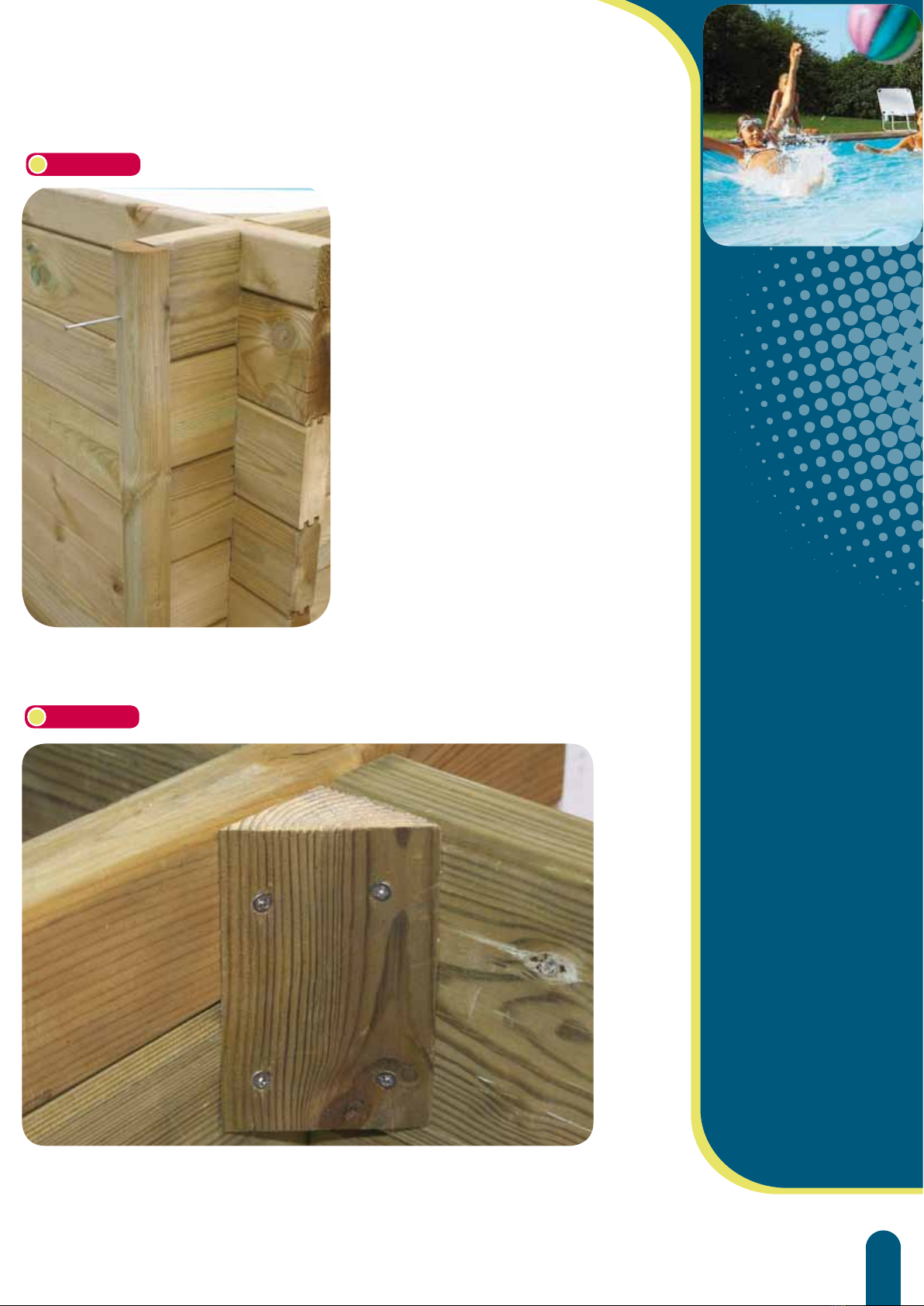
JOINED WOOD
To ensure the highest quality in the selection of our
wood, it is sorted meticulously before planing. Planks
that feature defects on both sides are taken out. Defects
(knots, cracks, flashes) are removed and the planks are
joined together (see the image above).
This is why it is not unusual to find joined elements in
a wooden pool, it in no way penalises the mechanical
properties of the wood. For the same reason, imperfections
on the interior surface of the pool (knots, cracks, flashes)
are entirely acceptable.
>>
SURFACE MOULD
Mould, caused by microscopic fungi, can grow on wood,
particularly on resinous species, on which the growth
can appear as «blueing». It is a surface phenomenon,
exacerbated by heat, humidity and inadequate aeration
and is characterised by stains raging from light to dark blue.
They can be removed by wiping the surface. Remember
that class IV treated wood is protected against attack
by fungi that could destroy the physical and mechanical
properties of the wood. For further information, please
refer to Procopi’s guarantees concerning the types of
wood and their treatment.
>>
COLOUR
VARIATIONS
Colour variations are common to
every species of wood. Treatment
brings them our because the depth
of penetration of the product will
depend on the wood density
and grain. Weathering of wood
outdoors will significantly attenuate
these colour variations.
WOOD,
A NATURAL MATERIAL.
Being a natural material, wood will have some imperfections. These are
normal and have no impact on the service life of the product.
A certain number are superficial and are not covered within the scope of
the guarantee.
CAUTION
storage. If you do not intend to assemble your pool immediately, you should store it without opening it in a well-
ventilated room, or failing this, in an area protected from humidity and sunlight. If, however, you were obliged to
unpack your pool, redo and restrap the pallet. Once the pallets are undone, the kit must be assembled within 24 to
48 hours.

47
>> TABLE OF CONTENTS
Foreword ................................................................................................................ P. 48, 49
Excavation and the rebar mesh .................................................... P. 50, 51
The metallic structure..................................................................... P. 52, 53, 54
Pouring the concrete slab .............................................................................. P. 55
Assembling the structure
.......................................................... P.
56-57-58-59
Mounting the support brackets...................................................... P. 60-61
Mounting the coping support fittings.................................... P. 62, 63
Liner locking track................................................................................................... P. 64
Finishing & wall piercings .............................................................................. P. 65
Mounting the pool fittings................................................................... P. 66, 67
Counter-swim prefitting & underlay................................................... P. 68
Fitting the liner & starting to fill the pool.................................... P. 69
Installation of the filtration system ............................................ P. 70, 75
Filling the pool and cutting out the liner...................................... P. 76
UW lights and coping................................................................................ P. 77, 78
Ladders................................................................................................................................. P. 79
Commissioning & operating tips ................................................ P. 80, 83
Guarantees ........................................................................................................... P. 84, 85
PEFC chain of custody certificate ....................................................... P. 86
Don’t play with safety ..................................................................................... P. 87

48
>> RECTANGULAR POOLS
Storage:
If you do not intend to assemble your pool immediately, you should store it
properly.
You should:
wLeave the pallet intact (or redo the pallet if it has been opened for
handling).
wStore the pool in an area protected from water and sunlight.
The aim is to avoid any warping of the wooden elements that could impede
correct assembly. If the pool is to be stored, we also recommend that you
insert little wooden wedges between each layer of wood to allow air to
circulate freely.
An above-ground kit
The kit delivered is intended for installation above-ground. If the pool is to
be installed partially or entirely in-ground, additional measures will need to
be taken:
w If the ground is not level, dig into the slope, never backfill under the pool.
w Take care to ensure sufficient drainage adapted to the terrain around the
periphery of the concrete slab.
w Cover the portion of the wall that is underground with a protective layer of
foundation grade plastic film.
w For backfilling around the pool use stabilised sand (mortar 150 kg/m3).
(Supplies necessary to implement these measures are not included in the kit)
Safety:
wYour installation should comply with the standard C15-100. Notably, the
electrical supply of the pump should be protected by a 30mA differential
circuit breaker. (Wiring should be carried out by a qualified professional).
wThe kit provided will allow installation of the filtration system 3.5 m from the
pool, this is in line with pool safety standards.
We recommend that you secure access to the pool using one of the
protective measures set out in the pool safety standards NF P 90-306,
307, 308 & 309 that is: Barriers - Alarms - Safety covers - Shelters.
wChildren should only use the pool under the supervision of an adult.
wRemember to remove the exterior wooden ladder while the pool is not in
use to prevent unsupervised access to the pool.
wThis pool is intended for private use only.
wDo not install the pool beneath electrical wires.
>> FOREWORD
Congratulations on your purchase. We have taken great care with the design and
manufacture of your pool, nevertheless, some precautions should be taken to ensure
that it is used correctly. Please read these instructions very carefully before beginning
assembly of your pool and keep it for future reference.
This document applies to all 3 pool sizes.
A detailed nomenclature of the various components specific to your pool is enclosed
in the liner package.
Wood is a natural
material, cracks
may appear but
these do not alter
the technical
characteristics of the
wood.
Similarly, wood
exposed to sunlight
can change colour
over time.
CAUTION
wAfter installing
your pool, keep
these documents
(installation
instructions and
invoice) in a safe
place. You will
need them for
future exchanges
with our various
departments.

49
QUICK OVERVIEW
>> Excavation
>> Assembly of the metal structure
>> Pouring the concrete slab
>> The wooden structure
>> The filtration group
Tools :
(excluding concrete works and excavation)
a decameter,
a rope, tube wrench (13 and 17), a mallet,
a screw gun (with a torx, pozi bit), a stanley knife, a metal saw, a big spirit
level, a flat head screw driver, a cross head screw driver, bolt cutters, sand
paper, a file, excavation equipment.
Time required :
w Excavation:
1 to 2 days (depending on the materials used)
w Metallic structure
1 day (with 2 people)
w Pouring the slab:
1 to 2 days (with 2 people and depending on the materials used)
w Wooden structure and filtration :
2 to 3 days (with 2 people). The time indicated does not include the
concrete curing time.
w Curing of the concrete slab before filling the pool with water : 2 to 3
weeks
50
>> RECTANGULAR POOLS
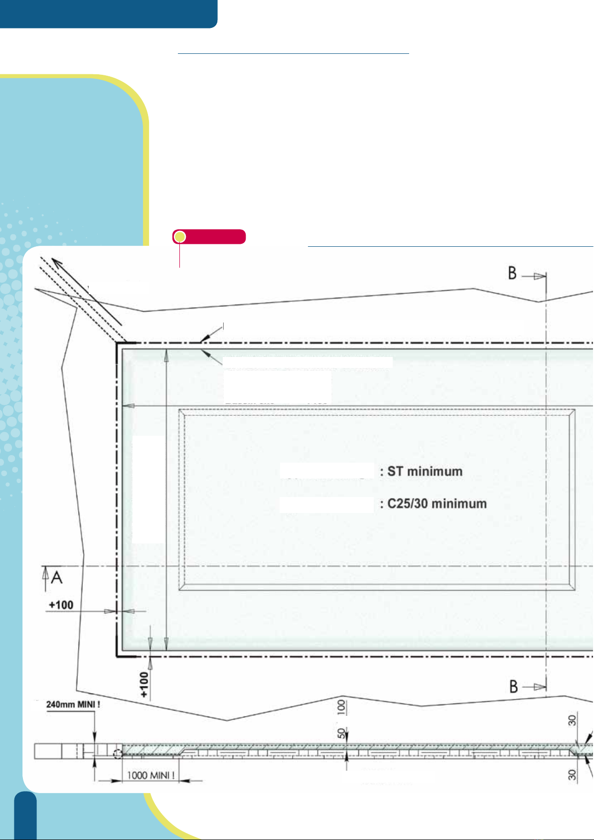
>> EXCAVATION & REBAR MESH
w After determining the ideal position for your pool, start with the
excavation required to accomodate the concrete slab that will form
the base of your pool. On fig. 1, identify those dimensions that
correspond to your pool.
w Never backfill under the pool to achieve a level surface, always dig
down so that your pool rests on a stable, level surface.
w Ensure that there is adequate peripheral drainage, especially if the
pool is to be installed in-ground.
w Seek the assistance of a professional if necessary.
Figure 1 DIMENSIONS OF THE EXCAVATION & THE CONCRETE SLAB
th
to
SECTION A-A
Rebar
Concrete
Pool 5x10 = 11100
Pool 4.8 = 9100
Pool 3x6 = 7100
Pool 5x10 = 6100
Pool 4.8 = 5100
Pool 3x6 = 4100
Outfall
EXCAVATION LIMIT (include a drain pipe, diameter 80mm)
SLAB LIMITS

51
Avoid siting your
pool beneath trees or
electrical lines.
Orient the pool such
that skimmers face
into prevailing winds.
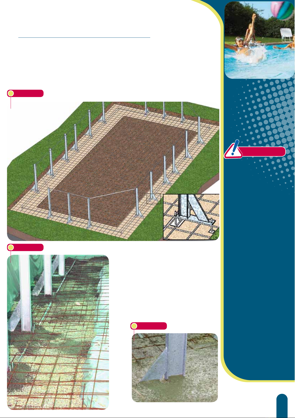
>> EXCAVATION & REBAR MESH
w Note that the excavation is deeper around
the periphery in order to accommodate the
reinforcing metallic structure. (fig. 2)
By deepening the excavation around the edges
only, you minimise the total volume of concrete
required to pour the slab.
Figure 2
w The bottom of the excavation should be perfectly level
to facilitate installation of the metallic structure. (fig. 3)
(either add a layer of compacted gravel or pour a rough
layer of concrete).
w Lay a rebar mesh over this section (fig 3) .
Figure 3
DIMENSIONS OF THE EXCAVATION & THE CONCRETE SLAB
Upper rebar mesh
Lower rebar mesh
Drain pipe
SECTION B-B
52
>> RECTANGULAR POOLS
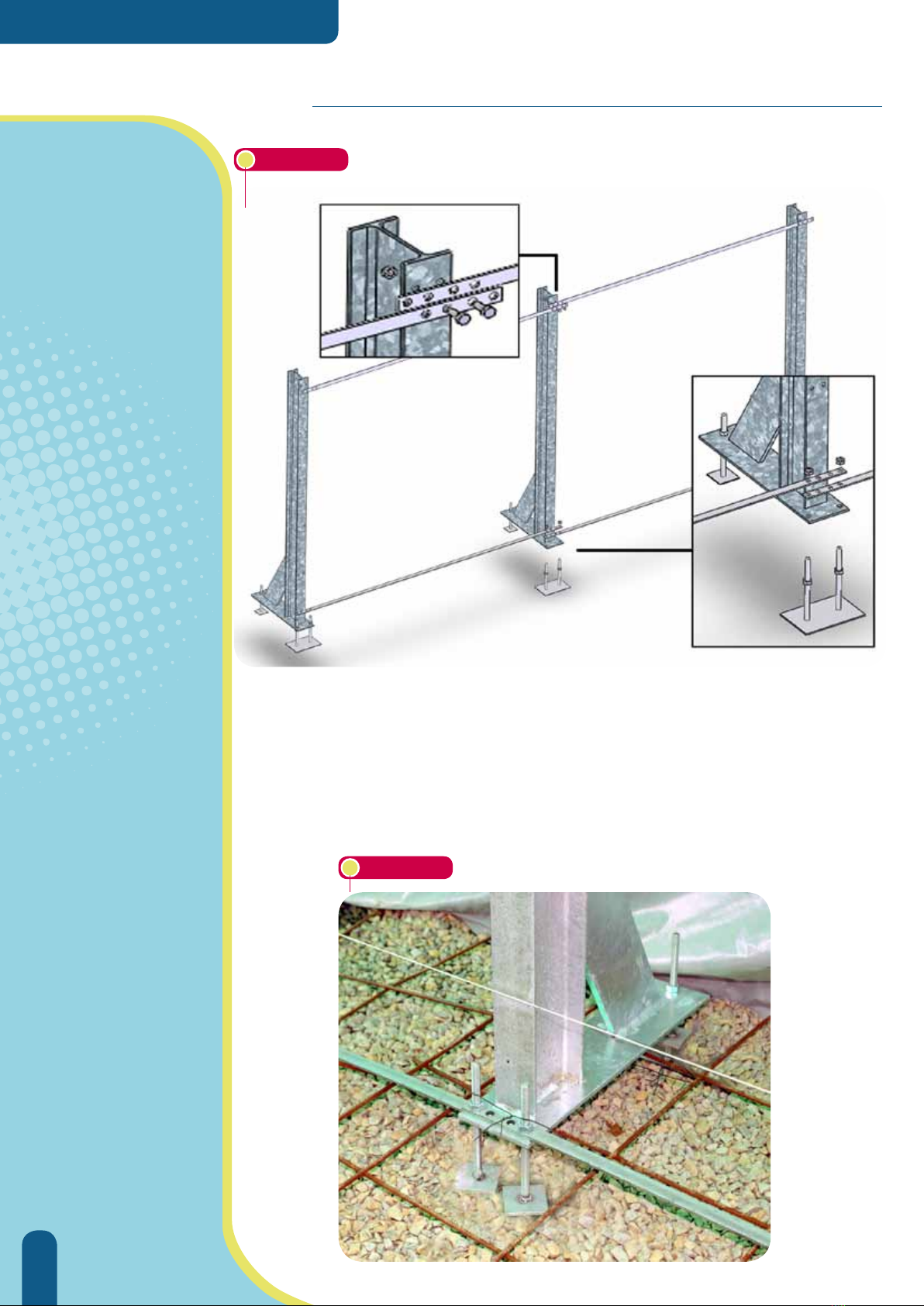
>> ASSEMBLY OF THE METALLIC STRUCTURE
wThe metallic structure comprises posts joined together by flat bars at the top and
bottom (fig. 4). Observe how these parts overlap to ensure correct positioning of
the structure. The top links should be dismantled once the slab has been poured.
Figure 4
wAfter correctly positioning the first layer of rebar (fig 3), set out the metallic posts required
to assemble your pool (fig 8). Make sure that you fit them with jacks first (fig. 4). These posts
are joined together at the bottom with flat bars fastened by two screws (bag of screws A
and B fig. 4).
w
The distance between the each post is determined by the length of the flat bars.
w
The flat bars features 4 holes at each end.
w
The upper and lower connection bars are identical.
w
Around the base, the outer holes are used while the inner holes are used on bars
around the top of the structure. (fig 6).
Figure 5
53
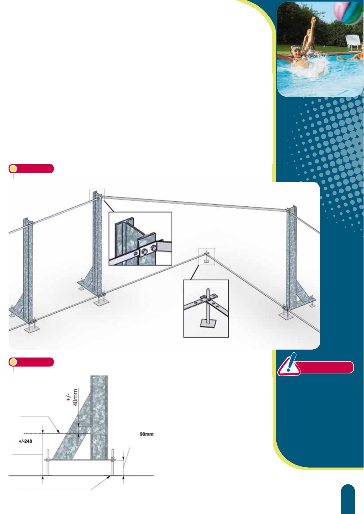
>> ASSEMBLY OF THE METALLIC STRUCTURE
wAfter correctly positioning the first layer of rebar (fig 3), set out the metallic posts required
to assemble your pool (fig 8). Make sure that you fit them with jacks first (fig. 4). These posts
are joined together at the bottom with flat bars fastened by two screws (bag of screws A
and B fig. 4).
w
The distance between the each post is determined by the length of the flat bars.
w
The flat bars features 4 holes at each end.
w
The upper and lower connection bars are identical.
w
Around the base, the outer holes are used while the inner holes are used on bars
around the top of the structure. (fig 6).
w
Once the metallic structure has
been assembled, adjust the
position of the posts carefully
and check :
• that the posts are level, straight
and perfectly aligned.
• that the pool diagonals
measured at the axis of the
corner jacks are equal. (fig 8)
Figure 6
Take particular care
during this stage of
the assembly, it will
impact subsequent
phases and
determine the quality
of the pool finish.
CAUTION
FB
Figure 7
Level of the
finished slab
GROUND - BOTTOM OF THE EXCAVATION
Slab
thickness
Height before
resurfacing

54
>> RECTANGULAR POOLS
wLay the top layer of rebar (second layer) over the entire surface of the excavation
before pouring the concrete.
wOnce laid, the metal trellis should cover the whole surface (lay the trellis such that it is
set 3 to 5 cm back from the edge around the entire periphery
). Some cutting around
the posts will be necessary (fig 9a.)
. Bars should be allowed to overlap and should be
connected together.
>> STRUCTURE
CAUTION
wOnce the
structure has
been assembled,
make sure that the
diagonals are equal
in length.
wCheck that the
posts are level and
straight.
wCheck that the
height is correct.
Diagram:
A represents a flat bar with an interaxial distance of 1m.
B represents a flat bar with an interaxial distance of 1.5m
C represents a flat bar for top corners
At the bottom corners, these flat bars are joined together by an AR type jack
(Detail fig.6)
Figure 8b
Figure 8c
Figure 8a
POOL
3X6
POOL
4X8
POOL
5X10
55
wLay the top layer of rebar (second layer) over the entire surface of the excavation
before pouring the concrete.
wOnce laid, the metal trellis should cover the whole surface (lay the trellis such that it is
set 3 to 5 cm back from the edge around the entire periphery
). Some cutting around
the posts will be necessary (fig 9a.)
. Bars should be allowed to overlap and should be
connected together.
Encase the base of
the metal posts with
a small amount of
concrete before
pouring the rest of
the slab, this will help
prevent deformation of
the metallic structure.
(fig. 9a).
See figures 7 and 9’ to
determine the correct
height of the concrete
slab with respect to the
posts.
The finish of the
concrete slab will
determine the correct
seating of the walls as
well as the quality of the
pool floor.
Figure 9
>> POURING THE CONCRETE SLAB
wWhile pouring the slab, make sure that the
upper rebar mesh is encased to a correct
depth in the concrete.
(minimum 3 cm)
wLevel the surface and smooth it as carefully
as possible in order to minimise protrusions
and asperities that will have to be corrected
later.
Figure 9b
Figure 9a
CAUTION
56
>> RECTANGULAR POOLS
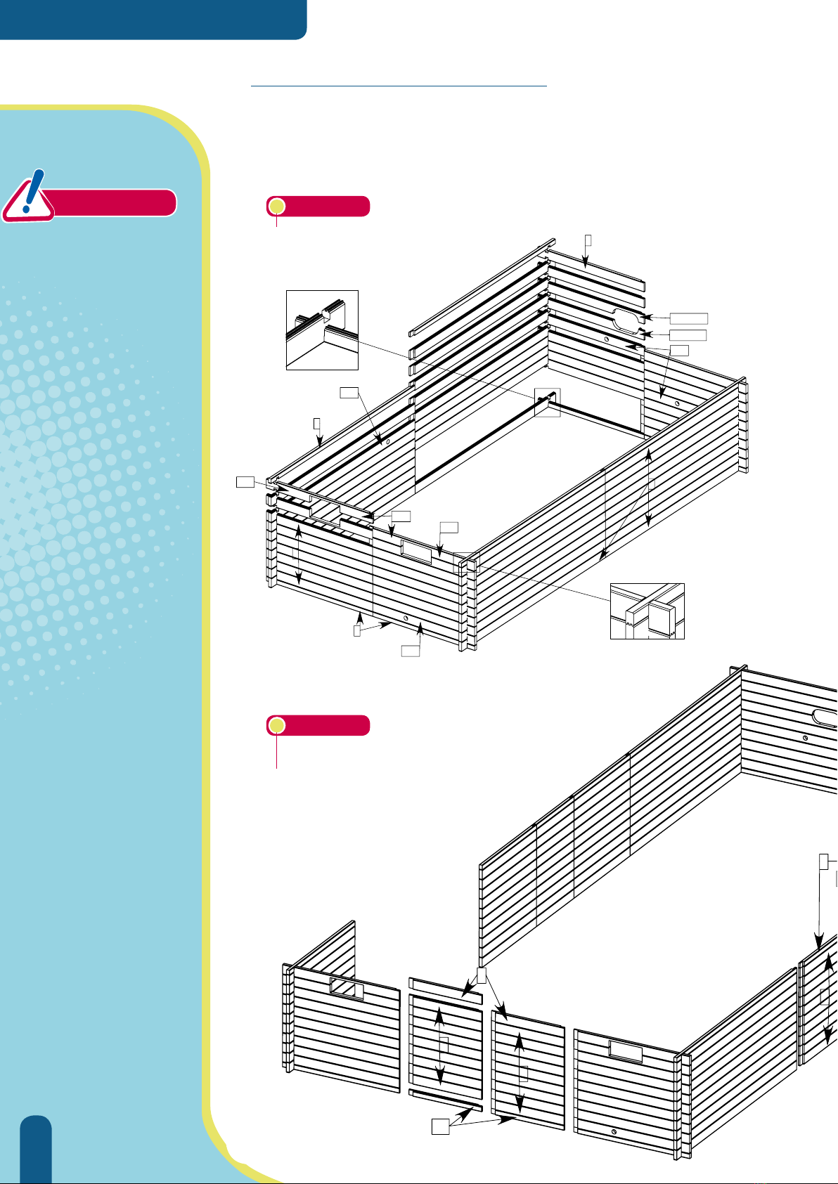
wYour pool comprises several types of wooden slat, the position of the various types
of slat are indicated in the various exploded views.
>> ASSEMBLING THE WALLS
Figure 10
CAUTION
wThe finish of the
concrete slab will
determine the
correct seating of
the walls as well as
the quality of the
pool floor.
wBefore starting to
assemble the wooden
walls, make sure
that the finish of
the concrete slab is
perfectly smooth and
level. Any uneveness
will be accentuated
and more noticeable
once the pool has
been filled with water.
If necessary, correct
defects by sanding or
resurfacing.
w
The slats comprising the pool corners are common to pools of all sizes. For the 4x8
and 5x10 pools, refer to the exploded view of the 3x6 pool.
6
4
4
3
9
11
4
10
3
POOL 5X10
11 rows of slats
Figure 11
wAssembly of the
wooden structure
may begin 2 to 3
days after the slab
is poured, it is not
necessary to wait for
the concrete to cure
completely.
However, you must
wait 2 to 3 weeks
before filling the
pool with water.
7
5SH
2SB
2PR
8
5
2
2SB
1
2Ncc H
2Ncc B
1BP
2PR
POOL 3X6
10 rows of slats

57
>> ASSEMBLING THE WALLS
6
4
11
10
4
Figure 12
1/2 FEMALE
SLAT
FEMALE
SLAT
MALE-FEMALE
SLAT
1/2 MALE
SLAT
POOL 4X8
11 rows of slats
w
The slats comprising the pool corners are common to pools of all sizes. For the 4x8
and 5x10 pools, refer to the exploded view of the 3x6 pool.
6
4
4
3
9
11
4
10
3

58
>> RECTANGULAR POOLS
w
Use a hammer and a clamp to gently tap the slats into position if necessary. Do not
strike the wooden slats directly, use the protective brace (supplied). Be careful to
ensure that each row of slats is fully engaged before starting with the next.
>>THE WOODEN WALLS (CONT)
wWhile assembling
the slats, make sure
as of the beginning
that the tongues
are fully engaged in
the grooves.
CAUTION
w
Start by unrolling the strips of asphalt (fig.
13) that will insulate the wooden structure
from the concrete slab.
w
Lay out the ½ slats ‘8’ that make up the
pool widths, then at the corners fit them
into the slats marked ‘1’ that make up the
lengths (fig. 14).
wThe slats should be fixed to the metallic
posts as they are slotted into position
(these are predrilled) with screws 6x30 from
bag D.
w
After positioning the 1st layer of slats,
check that the diagonals are equal.
w
Screw the slats together using screws from
bag C as shown in fig 14.
w
Be careful to remove any splinters as you
go.
81
5x40
sachet C
Figure 15
Figure 13
Figure 14
w
Fit together the remaining slats taking care that the slats machined to receive the
pool fittings are in their correct positions.
•The slats with the openings for the return fittings should be in the 6th row.
•
The slats machined to take the skimmers should be placed in rows 9 and 10 for the
3x6 pools and rows 10 and 11 for 4x8 and 5x10 pools.
•
The slat that will hold the vacuum point should be in row 8 of the 3x6 pool or row 9
of the 4x8 and 5x10 pools.
bag C

59
w
Use a hammer and a clamp to gently tap the slats into position if necessary. Do not
strike the wooden slats directly, use the protective brace (supplied). Be careful to
ensure that each row of slats is fully engaged before starting with the next.
Figure 16
5x100
w
Put the decorative profiles in
position covering the metallic posts.
They should be flush with the top of
the wooden wall.
w
Screw them in place from the inside
of the pool as shown opposite. (SS
screw 5x80 bag O). The top of the
profiles will be screwed together
when the coping support fittings
are mounted on top of the posts
(fig 22).
w
Eliminate any splinters raised by
screwing.
w
Should it be necessary to trim the
profiles to size (for example, if the
pool is partially in-ground) orient
the cut surface facing upwards.
wThe 2 profiles do not meet, the
metallic post remains visible.
5x80
w
Fit together the remaining slats taking care that the slats machined to receive the
pool fittings are in their correct positions.
•The slats with the openings for the return fittings should be in the 6th row.
•
The slats machined to take the skimmers should be placed in rows 9 and 10 for the
3x6 pools and rows 10 and 11 for 4x8 and 5x10 pools.
•
The slat that will hold the vacuum point should be in row 8 of the 3x6 pool or row 9
of the 4x8 and 5x10 pools.
Figure 17
>>THE WALLS (CONT) & DECORATIVE PROFILES
60
>> RECTANGULAR POOLS
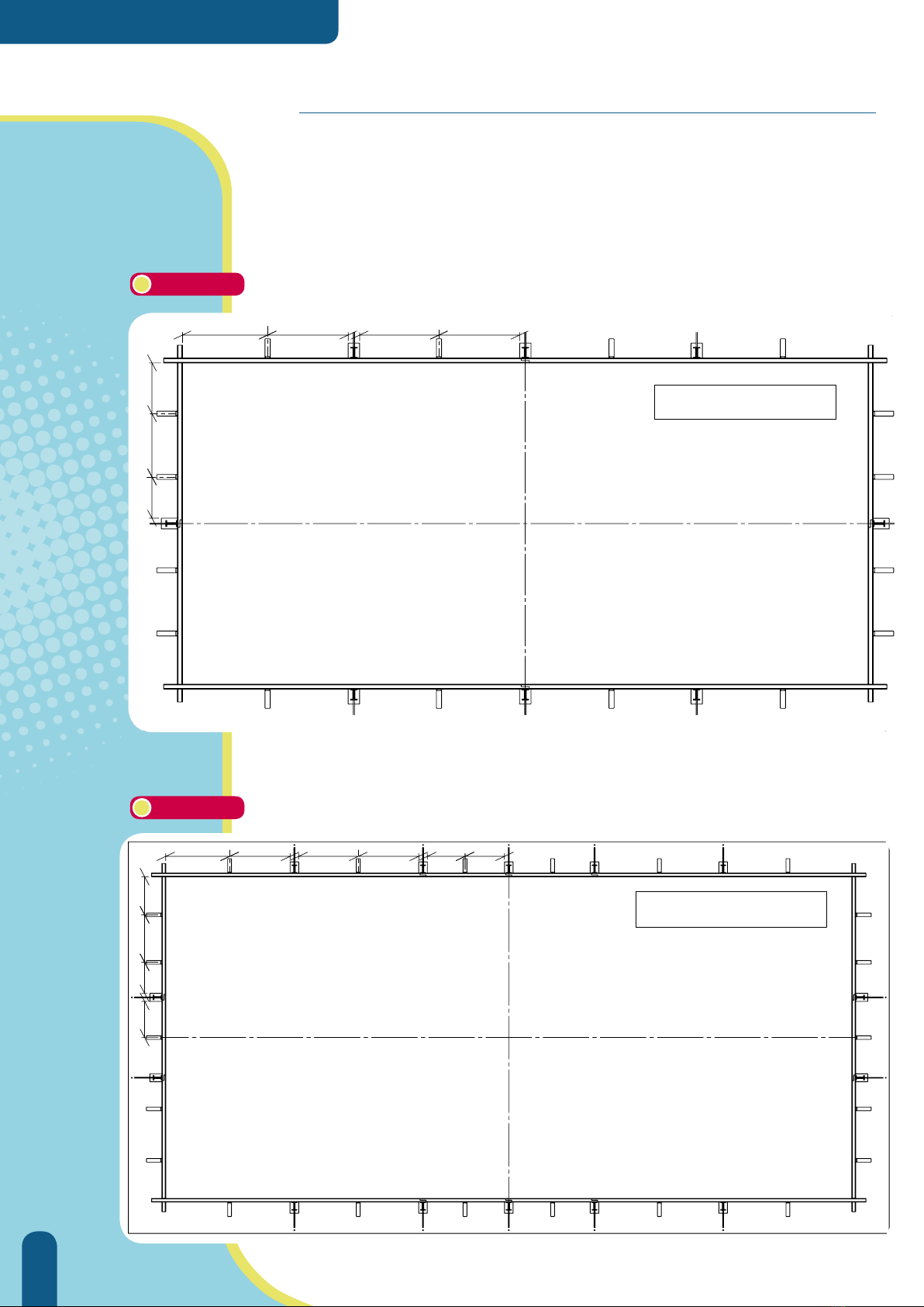
>>
MOUNTING THE COPING SUPPORT BRACKETS
700725 700
385 590
725
475
bassin 3x6
475475700700725 725
475590385
450
bassin 4x8
Figure 18
Figure 19
w
Refer to the diagram that corresponds to your pool before mounting the wooden
support brackets. Use the 5x100 SS screws from bag L to fasten them in position. The
brackets should be installed 3mm down from the top of the wall (fig. 21). To ensure that
the brackets are correctly positioned use the support bracket plates that will be fastened
to the brackets, these should be flush with the top of the wall. Before screwing the
plates into position, lightly mill the central holes through which the screws (5x40) will be
inserted.
Pool 4x8
Pool 3x6
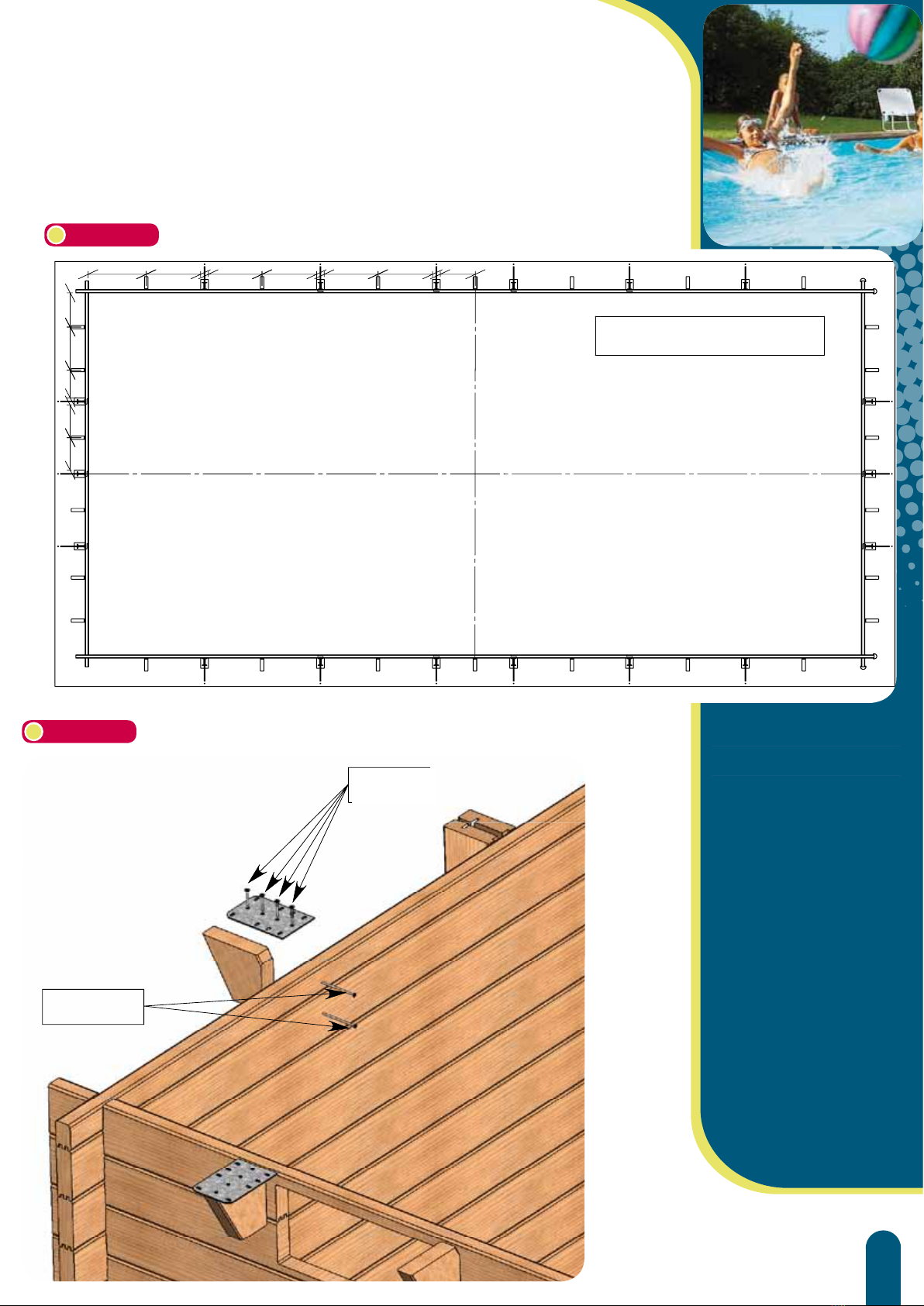
61
725 725 700 700 700 700 450
475385450450 590
bassin 5x10
5x100
4x40
Figure 20
Figure 21
5x40 TIP :
Chamfer the edge of
the central holes in the
support bracket plates
so that they can be
correctly screwed into
position.
Make sure that the
plates are level to
facilitate subsequent
laying of the coping.
Pool 5x10

62
>> RECTANGULAR POOLS
The coping
support fittings are
designed to hold
the coping modules
and fix them in
position.
CAUTION
w
Place the metal fittings that will hold the coping on top of the posts. Make sure that
they are flush with the top slat and that they are aligned with each other and with the
support bracket plates along the lengths of the wall. Use the 6x30 Torx screws from
bag E.
>>
MOUNTING THE METAL FITTINGS
Figure 22
Figure 24
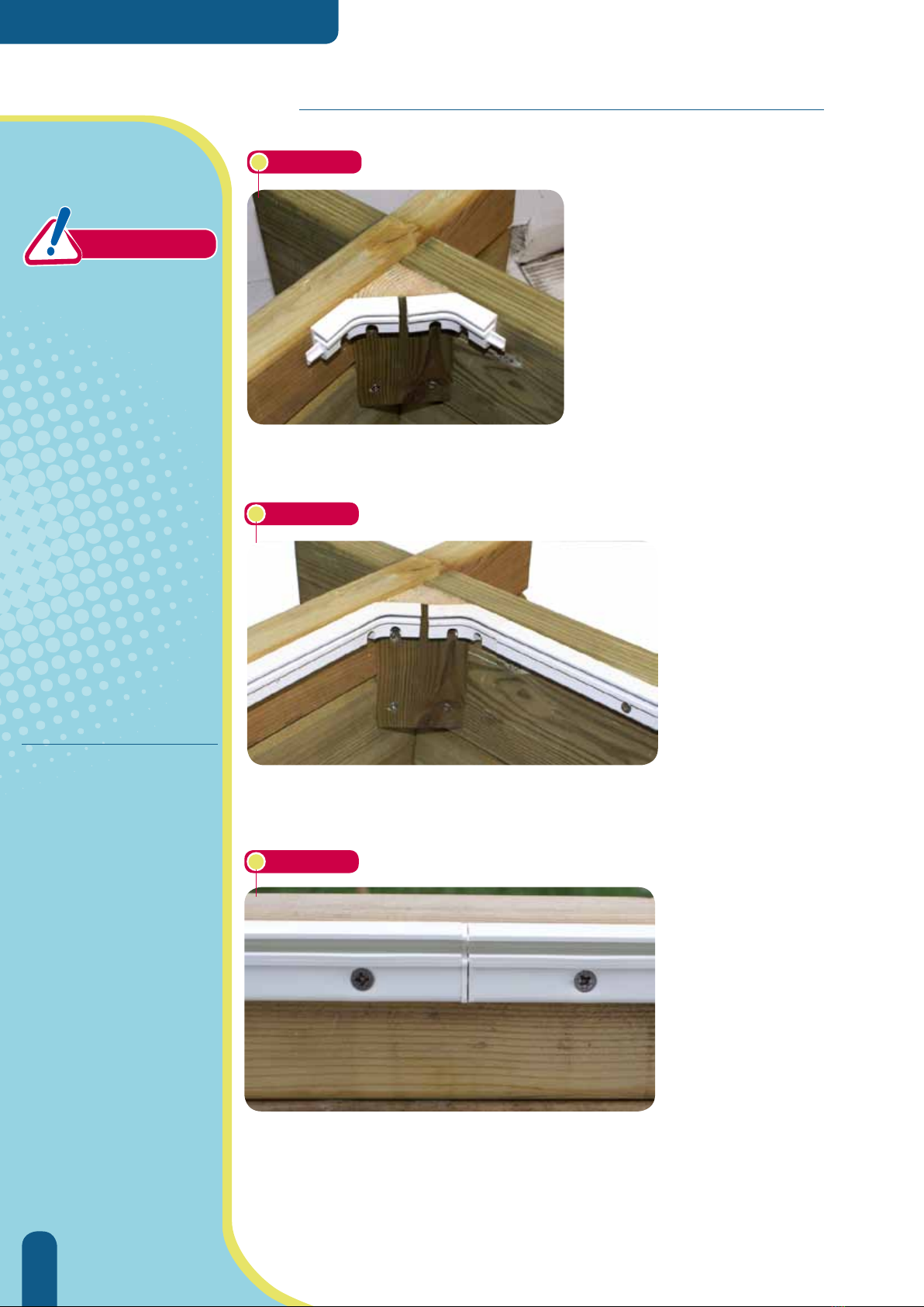
wIn the corners, use the remaining left and right fittings and 4 corner
brackets.
63
w
Attach decorative profiles to the ends of each
wall using 3 evenly spaced nails from bag I.
The decorative profiles should be predrilled
along their axis.
If you need to trim the profiles, orient the cut
side so that it is facing upwards.
Figure 23
Figure 25
w
In each corner, mount a wooden triangle to support the liner locking track
corner elements. (stainless steel screw 5x40 bag C)
64
>> RECTANGULAR POOLS
>> MOUNTING THE LINER LOCKING TRACK
Before beginning
to mount the liner
locking track,
make sure that the
structure has been
correctly assembled.
To do this:
wuse a spirit level
to verify that the
structure is level
around the entire
periphery,
w
check that the
diagonals are equal
in length,
wcorrect any
imperfections
before continuing.
CAUTION
wPosition 2 liner locking track corner
pieces in each corner. (You will find
the parts in the liner/ waterproofing
kit). You will need to trim an
interlocking pin off each corner piece.
Make sure that the 2 corner parts are
level with each other and flush with
the top of the wall. A gap of a few
mm between the two parts is not
problematic. Use 4x35 stainless steel
screws from bag H.
TIPS:
w
The track should be
perfectly flush with the
top of the wall.
w
Before fixing the track
in position, pre-drill
the holes using the Ø
4mm drill bit provided.
(bag J)
w Remember to deburr
the track after making
the cuts.
w Take care not to
overtighten to ensure
that the screws do not
break through the track.
Figure 27
Figure 26
wContinue to mount the
locking track using the
lengths provided, these
should abut the locking
track junctions (fig 28).
Insert a screw (stainless
steel 4x35 from bag H) at
20cm intervals. Locking
track junctions do not
necessarily line up with the
post interaxial distance.
Towards the end, it will
be necessary to trim the
lengths. Cut the length
to size between two liner
locking junctions then
bend the track to allow
the junction pins to fit into
place.
Figure 28
Table of contents
Other Procopi Swimming Pool manuals

Procopi
Procopi ODYSSEA RECTANGLE User manual

Procopi
Procopi Proswell Tropic OCTO User manual

Procopi
Procopi Piscines Bois ODYSSEA OCTO User manual

Procopi
Procopi Delta STARDECK User manual

Procopi
Procopi ProSwell TROPIC JUNIOR User manual

Procopi
Procopi ProSwell Weva octo 440 User manual

Procopi
Procopi OCTO+ PRO User manual


