PRODEM DCS Series User manual
Operating- and maintenance manual
Service manual
Spare parts lists
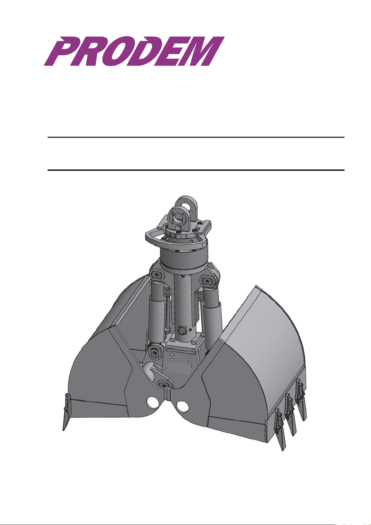
Clamshell grab –Model line DCS

Clamshell grab
2
Table of contents:
Part 1. Operating manual.....................................................................................................3
1.1
Product identification:.................................................................................................3
1.2
Terms of guarantee:...................................................................................................4
1.3
General safety instructions:........................................................................................5
1.4
Product information:...................................................................................................6
1.4.1
Assembly:............................................................................................................6
1.4.2
Product description:.............................................................................................6
1.4.3
Design features: ..................................................................................................6
1.4.4
Plug system:........................................................................................................6
1.4.5
Measures / Technical data:..................................................................................7
1.4.6
Recommended Hydraulic fluids:..........................................................................7
1.4.7
Employment:........................................................................................................8
1.5
Transport / Storage: ...................................................................................................9
1.6
Installation and initiation:..........................................................................................10
1.6.1
Positions of the hydraulic connectors at the rotator:..........................................11
Part 2. Service manual ......................................................................................................12
2.1
Inspection:...............................................................................................................12
2.1.1
Items of daily inspection: ...................................................................................12
2.1.2
Items of weekly inspection:................................................................................12
2.2
Maintenance.............................................................................................................13
2.2.1
Items of daily maintenance / after 8 operating hours:........................................13
Part 3. Spare parts lists: ....................................................................................................14
3.1 DCS05 / Z-Z05 with AG 5-2 .....................................................................................14
3.1.1
DCS05 / Z-Z05 - Grab cpl. - Spare parts ...........................................................14
3.1.2
DCS05 / Z-Z05 - Grab cpl. - Picture...................................................................15
3.1.3
DCS05 / Z-Z05 - Cylinder - Picture/spare parts.................................................16
3.2 DCS1 / Z-Z1 with AG 5-2 .........................................................................................17
3.2.1
DCS1 / Z-Z1 - Grab cpl. - Spare parts...............................................................17
3.2.2
DCS1 / Z-Z1 - Grab cpl. - Picture.......................................................................18
3.2.3
DCS1 / Z-Z1 - Cylinder - Picture/spare parts.....................................................19
3.3 DCS2 / Z-Z2 with AG 5-2 .........................................................................................20
3.3.1
DCS2 / Z-Z2 - Grab cpl. - Spare parts...............................................................20
3.3.2
DCS2 / Z-Z2 - Grab cpl. - Picture.......................................................................21
3.3.3
DCS2 / Z-Z2 - Cylinder - Picture/spare parts.....................................................22
3.4 DCS3 / Z-Z3 with TH609H-2-G3/4” ..........................................................................23
3.4.1
DCS3 / Z-Z3 - Grab cpl. - Spare parts...............................................................23
3.4.2
DCS3 / Z-Z3 - Grab cpl. - Picture.......................................................................24
3.4.3
DCS3 / Z-Z3 - Cylinder - Picture/spare parts.....................................................25
3.5 DCS4 / Z-Z4 with AB1000-30-PV.............................................................................26
3.5.1
DCS4 / Z-Z4 - Grab cpl. - Spare parts...............................................................26
3.5.2
DCS4 / Z-Z4 - Grab cpl. - Picture.......................................................................28
3.5.3
DCS4 / Z-Z4 - Cylinder - Spare parts.................................................................29
3.5.4
DCS4 / Z-Z4 - Cylinder - Picture.......................................................................30
3.6 DCS5 / Z-Z5 with AB1500-31-PV.............................................................................31
3.6.1
DCS5 / Z-Z5 - Grab cpl. - Spare parts...............................................................31
3.6.2
DCS5 / Z-Z5 - Grab cpl. - Picture.......................................................................32
3.6.3
DCS5 / Z-Z5 - Cylinder - Spare parts.................................................................33
3.6.4
DCS5 / Z-Z5 - Cylinder - Picture.......................................................................34

Clamshell grab
3
Part 1. Operating manual
1.1
Product identification:
Position of identification data
1
1. Serial number –rotator
(on identification plate –rotator) 2
2. Serial number –grab
(stamped onto frame) 3
3. Identification plate -grab
Explanation of identification plate
Contact postal address
Max. lifting capacity –grab
Max. working pressure - turning
Max. oil amount - turning
Max. working pressure –griffin
Max. oil amount –griffin
Max. weight of carrier machine
Identification information: Trader- / customer number
Type designation –grab:
Serial number –grab:
Serial number –rotator:
Type designation –carrier machine:
Day of delivery:
Trader information:
Name: Branch:
Address:
Customer number:
Phone: Fax:
E-Mail: Contact person:

Clamshell grab
4
1.2
Terms of guarantee:
A) Guarantee period
Prodem offers a guarantee period of 12 months after delivery of the product.
B) Guarantee extent
The guarantee shall include all parts showing defects which are traceable to material or production faults.
C) Guarantee completion
a)
Guarantee claims must be submitted to Prodem in writing (see D Guarantee notification).
b)
Defective parts, replaced within the scope of the guarantee, shall remain the property of the HGT. Upon request they
must be delivered immediately to the manufacturer for the purpose of guarantee claim settlement (see E Allocation).
c)
Spare/replacement parts must be ordered from Prodem on account.
d)
After the investigation by Prodem, an evaluation and a written statement are made and if necessary a credit note of
the resultedcosts.
D) Guarantee notification
Guarantee claims must be submitted to PRODEM in writing within 4 weeks after the damage or fault has occurred and
must include the following information:
Type identification number of PRODEM product
Factory and, where necessary, rotator IDnumber
Denotation of the defective part ( if possible with PRODEM - spare part number )
Date and kind of thedamage
Possible cause of damage (photographs asrequired)
Information about deployment and carrier machine ( digger / crane)
E) Allocation
Defective parts must be made available free of charge for PRODEM min. 6 weeks after guarantee notification for
investigation of the defect. Defective parts which are not returned to PRODEM/and/or are not made available for the
investigation are excluded from the guarantee.
F) Guarantee exclusion
The following shall be excluded from the guarantee:
Damage incurred by improper assembly of machine parts and/or hydraulic components, as a result of improper
use or maintenance or damage incurred duringtransport.
Defects which are traceable to repairs carried out by a non-authorised third party.
Defects incurred by the use of foreign spareparts.
Damage to parts subject to normal wear, such as e.g.: sleeve bearings, hoses, bolts etc.
Secondary damage traceable to the delayed replacement of wearable parts.
If repairs are carried out independently by the owner on machine parts during the guarantee period without the prior
consent of the manufacturer (PRODEM), guarantee and/or liability claims shall become void.
G) Guarantee claims
Guarantee claims shall only relate to the possible cost-free delivery of replacement parts. Travel and wage costs shall be
subject to negotiation.
We reserve ourselves to adapt assembly/disassembly hours in individual cases on a necessary measure. To customer
service expenditures the following, firm sentences apply:
Assembly/disassembly by mechanic
Travel expenses of mechanic, vehicle included
H) Special arrangements
Special arrangements according to the specified points 1-5 are to be submitted in writing before conclusion of the sales
contract and be confirmed by PRODEM in writing. Later special arrangements cannot be considered.
I) Contact –guarantee: PRODEM

Clamshell grab
5
1.3
General safety instructions:
Please observe the following items before assembling or operating this machine component:
1. First read this operating manual thoroughly!
Should unclear points or questions arise when reading through this operating manual, please
consult you supplier in the first instance.
2. Check whether your carrier machine if suitable for this product!
3. Acquaint yourself with the safety regulations applicable at your place of
Work!
4. If you do not comply with the information and instructions given in this operating manual, all
guarantee and/or liability claims shall beexcluded.
The grab is constructed according to the present state of technology and complies with the currently
applicable safety regulations. Unforeseeable factors may, however, affect the safety of the grab.
It is therefore extremely important to precisely adhere to the safety regulations.
Safety rules:
1. Any damage to the grab must be repaired immediately by a qualified technician.
If necessary, the assistance of the supplier or manufacturer must be called upon.
2. The grab must only be deployed for carrying out tasks for which it is intended.
3. Unauthorised persons must keep clear of the working area of the carrier machine and
the grab.
4. Observe all safety regulations applicable at your place of work.
5. Protection or safety devices must not be removed. In the event of damage or loss these must be replaced
immediately.
6. When assembling or disassembling the grab, ensure that all connections and attachments are secured in
accordance with the regulations.
7. When repositioning the machine, ensure that the grab is in a safe position. Secure the grab e.g. with
chains in order to prevent all uncontrolled movements.
8. When carrying out repairs, only use original replacement parts. If foreign parts are used, the safety of
the grab can no longer be guaranteed.
9. Also observe the additional safety regulations given in this operating manual.
Safety regulations are only effective provided these are known and understood.
Please consult your supplier if questions arise.
Clamshell grab
6
1.4
Product information:
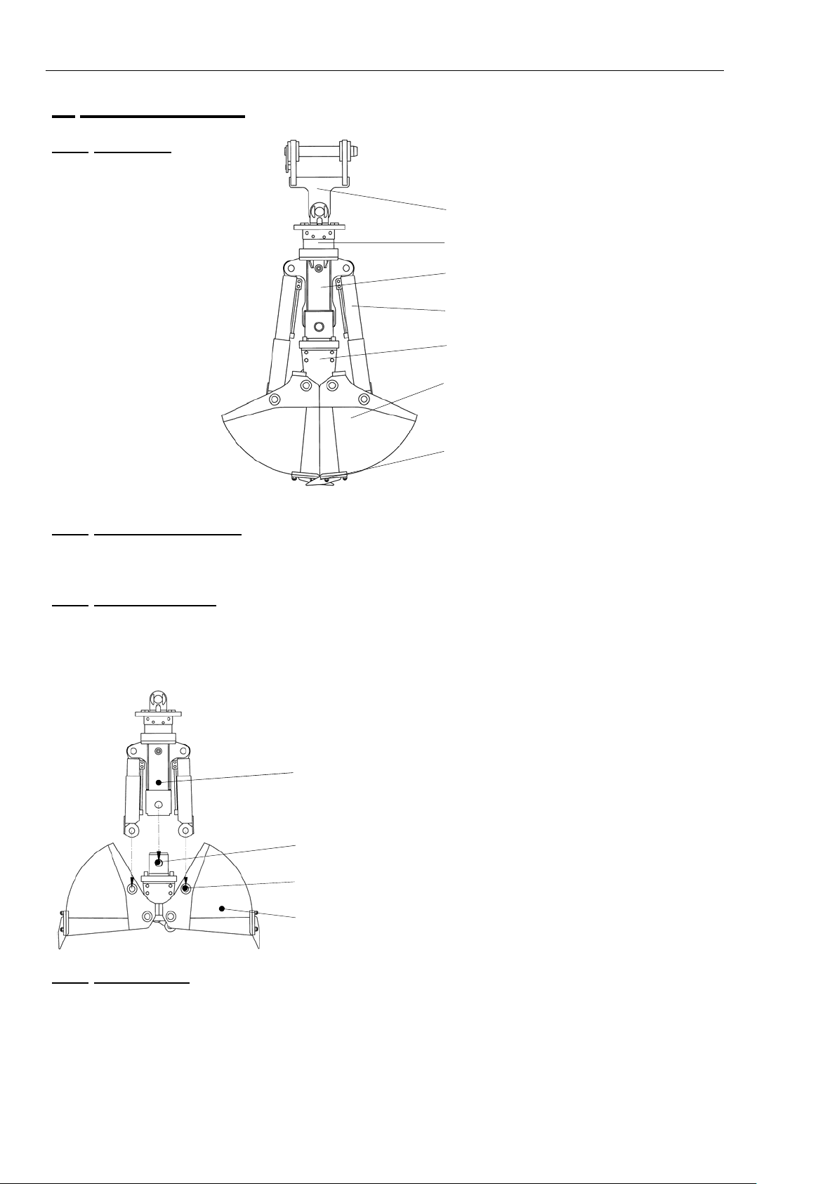
1.4.1
Assembly:
Suspension
Rotator
Frame
Cylinder
Clamshell carrier
Clamshell
Exchange teeth
1.4.2
Productdescription:
Special clamshell grabs for hydraulic excavator use as excavating and dredging of grown soil, pulling ditches
and cable pits, shipping bulk materials.
1.4.3
Design features:
-
Multi-functional clamshell grab for oscillatinguse
-
Clamshell with clamshell carrier exchangeable within the entire line of products
-
Rotator with endless hydraulicrotation
-
Hose protection for rotatorconnection
-
Exchange teeth out of high density resistant steel 400HB
Control unit
(Frame with connector and hydraulic unit)
Socket pin - frame
Socket pin - cylinder
Clamshell carrier with clamshell
1.4.4
Plug system:
The Clamshell grabs of the series DCS2 –DCS5 are equipped with a plug system, which makes it possible to quick
change the clamshell with clamshell carrier and synchronisation steering element.
Only the two lower cylinder socket pins and the frame socket pin are to be detached in order to change the clamshell.
This economical solution makes a versatile employment, with only one control unit and with the most different clamshell
sizes and clamshell forms, possible for the customer.
Clamshell grab
7
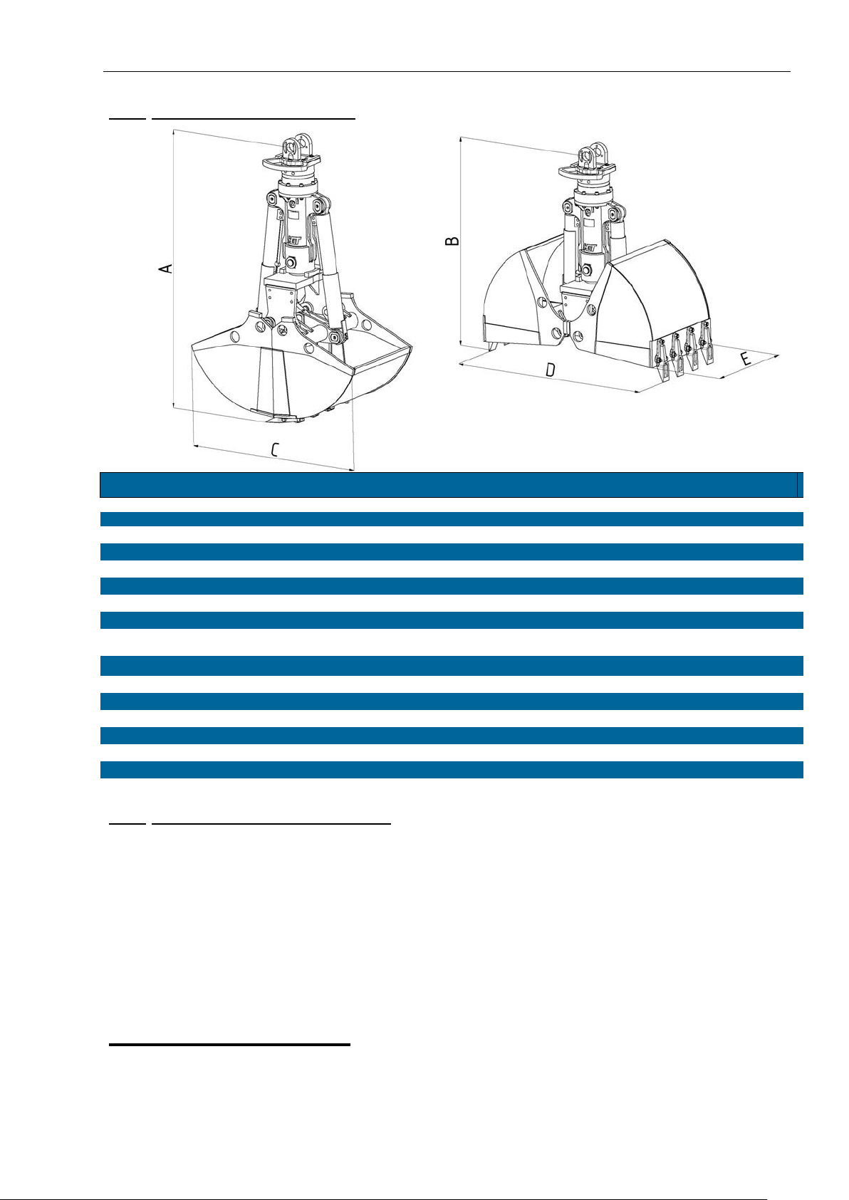
1.4.5
Measures / Technicaldata:
Model
DCS05
DCS1
DCS2
DCS3
DCS4
DCS5
Excavator weight class
t 1 –2
1 –4
4,5 –8
9 –12
13 –21
22 –30
Max. lifting capacity clamshell
t 1
1
2
2
4
6
Max. lifting capacity rotator
t 2
4
4
10
10
15
Measure A
mm 865
885
1230
1695
2100
2380
Measure B
mm 670
630
890
1340
1610
1790
Measure C
mm 700
840
1180
1295
1490
1730
Measure D
mm 790
950
1305
1410
1700
2000
Cut width E
mm 280-400
300-500
270-600
300-800
300-1000
400-1200
Max. bulk density
t/m32
2
2
2
3
3
Max. closing pressure
kN 20
24
27
40
67
95
Max. working pressure griffin
bar 250
250
300
350
350
350
Max. working pressure turning
bar 250
250
300
320
320
320
Hydraulic connection griffin
M18x1,5
M18x1,5
M18x1,5
G3/4
G3/4
G3/4
Hydraulic connection turning
M18x1,5
M18x1,5
M18x1,5
G1/2
G1/2
G1/2
Max. oil consumption griffin
l/min 25
25
50
60
90
120
Max. oil consumption turning
l/min 20
20
20
20
25
25
1.4.6
Recommended Hydraulicfluids:
Hydraulic fluid H-LP e.g.: Mineral oilHLP46
Hydraulic fluid HE ES e.g.: Panolin HLP Synth32/46/68
Synthetic ester oils Ukabiol HE46
DEA ECONA E46
Agip Arnica S46
Hydraulic fluid HE TG e.g.:
Plant oils Ukabiol HY 32
Brennrag HV32
Hydraulic fluids HFC, HFD, HFA, and HFB are not recommended!
Filter designs for min. oil purity according to DIN ISO 4406. Class 18/16/13
Recommended lubricating greases:
Lubricating grease e.g.: ESSO - MULTI-PURPOSE GREASE (Moly)
ESSO - Joint grease 2-083
Lubricating grease e.g.: AVIA - AVIALITH 2 F(water-resistant)

Clamshell grab
8
1.4.7
Employment:
Operating regulations:
1.
Take care to comply with the regulations for operating the carrier machine and the functions necessary for working
with the grab.
2.
Ensure that all persons keep well clear of the working area of the carrier machine and the grab.
3.
Only use the grab to carry out work for which it isdesigned:
Excavating andshipping
4.
Do not use the clamshell grabfor:
Hammering
Striking
Tamping
Crushing –The rotary function is not a crushingdevice!
Coiling –Rotation device is for positioning thegrab!
Moving of containers andwaggons!
! In the event of improper use all guarantee and / or liability claims shall become void.
Grab is designed for free oscillating
employment!
Load admission only in vertical grab
axle!
Do not pull loads with
the grab!

Clamshell grab
9
1.5
Transport / Storage:
The transportation and lifting or lowering of the grab must be carried out using the tools provided for this
purpose.
Transport: -Grab installed at the carrier machine (Pict.1):
The grab is determined to the transportation claw of the excavator and secured (see
operating manual of the excavator)
-The grab is transported in open position (Pict.2):
Place the grab on an even, stable surface (! sharp knives) and take precautions to prevent it
from tipping over and slipping. The same is valid during the storage of the grab.
-The grab is transported/stored in horizontal position (Pict. 3):
Stabilize the grab under the rotator while storing. Take precautions to prevent it from tipping
over and slipping during the transport.
Pict. 1 Pict. 2
Pict. 3
! Before longer storage the grab must be cleaned and maintenance
completely first. An oil exchange is recommended before any further
employment! Seals and hoses age, become useless and have to be
exchanged in time.
Lifting / moving
Always lift the grab at the connection point provided(Pict. 4). Pict. 4
! The following checks must be carried out after each transport:
Visual check for transport damages
Check grab for missing parts (see spare parts list)
Check firm seat of screws, bolts and safetydevices
Check for leaks in the hydraulic system
If any defects are detected the grab must be repaired immediately by a qualified technician before
employment.

Clamshell grab
10
1.6
Installation and initiation:
The carrier machine must fulfil the following requirements:
1. The carrier machine must be fitted with a safe hydraulic unit.
In order to realise the two basic functions (rotation and opening/closing) of the grab,
two separate hydraulic circuits are necessary.
2. Make yourself acquainted with the hydraulic connection layout for the carrier machine.
Errors in the operating logistics must not endanger the safety of thefunctions.
4. The adapter unit (adapter/suspension/connector) between the carrier machine and the grab must be
designed for the working load of the grab.
! Only use original parts.
5. The working load of the excavator must match the grab type (see 1.4.5 Excavator weight class).
6. Connection values (pressures, delivery volumes) must be checked in advance for compliance with the
correct specifications (see 1.4.5 Technical data)
! Never change the pressure and volume settings of safety valves without the permission of the
manufacturer.
-Check whether the connection hoses (excavator - grab) have the correct length and are appropriate
for the grab operatingpressure.
-Ensure that the correct hoses and connectors are used (Table 1). Take care to follow the supplier’s
specifications.
! Improper connectors and/or incorrect hose connections may lead to malfunctioning and damage
to the grab.
Attachment:
-Attach the adapter/suspension to the admission on the excavator arm using the stud bolt (Pict. 1/2).
Follow thereby the instructions of the supplier of the carriermachine.
-Attach the hoses to the rotator according to their respectivefunctions.
Consider thereby the connection symbols next to the screw threads on the rotator (Pict. 3).
! Ensure absolute cleanliness when attaching all hydraulic hoses. Dirt will damage your hydraulic
system.
Pict. ½

Clamshell grab
11
1.6.1 Positions of the hydraulic connectors at the rotator:
DCS05 –DCS2 DCS3 –DCS4 DCS5
Pict. 3
Thread sizes (Internal threads in the rotator)
Connecting thread
DCS05
DCS1
DCS2
DCS3-S
DCS4
DCS5
R1 rotate left
M18x1,5
M18x1,5
M18x1,5
G1/2
G1/2
G1/2
R2 rotate right
M18x1,5
M18x1,5
M18x1,5
G1/2
G1/2
G1/2
GS close grab
M18x1,5
M18x1,5
M18x1,5
G3/4
G3/4
G3/4
GO open grab
M18x1,5
M18x1,5
M18x1,5
G3/4
G3/4
G3/4
Table 1

Clamshell grab
12
Part 2. Service manual
2.1
Inspection:
Acquaint yourself with the safety regulations applicable at your place of work first.
Inspection
During maintenance and inspection work the grab must be placed on a stable and even surface.
a) Place the grab on the ground
b) Switch off the motor of the carriermachine
c) Remove the starter key from the carrier machine
d) Block the machine
e) Ensure that the hydraulic system is depressurized
f) During inspection/maintenance work place a sign in the machine cabin reading
“Do not start / operate”
2.1.1
Items of dailyinspection:
- Visual check whether any parts are missing
- Visual check whether any parts are loose (screws, bolts and safety devicesetc.)
- Visual check for leaks in the hydraulic system (connectors, hoses, cylindersetc.)
- Visual check for signs of mechanical damage (cracks, deformationsetc.)
2.1.2
Items of weeklyinspection:
Check the grab for signs of wear
- Play in the bearings (steering element, clamshell, cylinder, adapter)
- Exchange teeth
- Stops opening limit - opening min. lifting cylinder assembly dimension (Table 1 - measure E)
- Exchange teeth limit - closing max. lifting cylinder assembly dimension (Table 1 - measureE)
In case of noticeable wear or other defects contact your supplier immediately and arrange for parts to be
replaced or repaired.
Assembly
dimensions
Opening / E min.
Closing / E max.
DCS05
80 mm
290 mm
DCS1
80 mm
290 mm
DCS2
365 mm
520 mm
DCS3
565 mm
815 mm
DCS4
670 mm
1015 mm
DCS5
780 mm
1195 mm
Clamshell grab
13
2.2 Maintenance
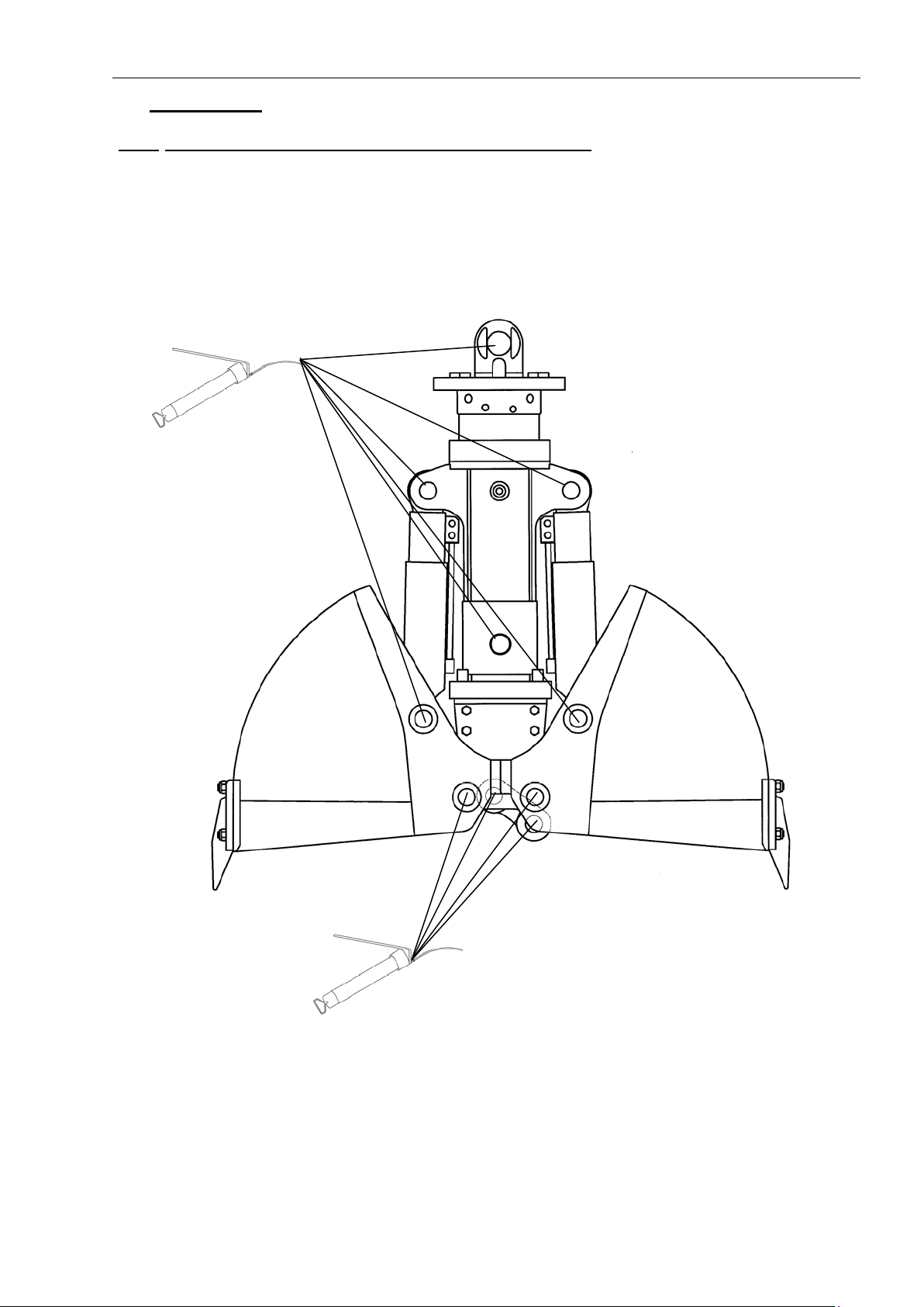
2.2.1
Items of daily maintenance / after 8 operatinghours:
- All bearings (Pict. 2) should be lubricated at least 1x daily and/or after 8 operating hours with multi-
purpose grease

Clamshell grab
14
Part 3. Spare parts lists:
A –Replacement part / E –Spare part / S –Set / V –Wearing part
Ma= Torque
= Description of adhesive:
Secured with medium strength screw adhesive
(e.g. Loctite 638)
3.1
DCS05 / Z-Z05 with AG 5-2
3.1.1
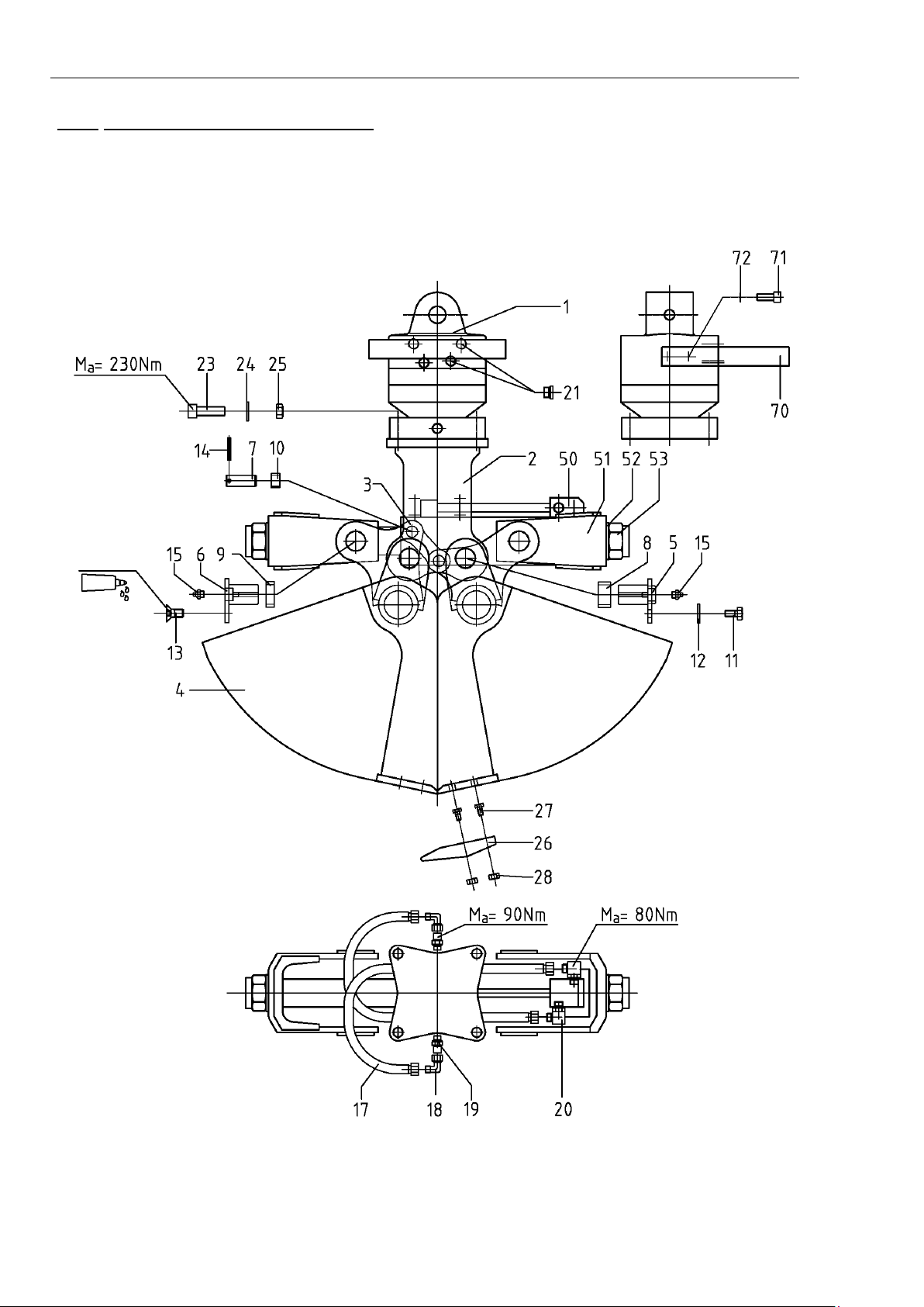
DCS05 / Z-Z05 - Grab cpl. - Spareparts
Item
Pc.
Designation
Group
Order-No.
1
1
rotator
E
3007000119
2
1
frame
E
2002001001
3
2
steering
E
2004001001
4
1
clamshell with steering –280
E
2006001010
clamshell with steering –300
E
2006001011
clamshell with steering –400
E
2006001012
5
4
pin –frame/clamshell
V
3009035005
6
4
pin –cylinder/clamshell
V
3009035004
7
4
pin –steering
V
3009020001
8
4
bush –frame/clamshell
V
5003002103
9
4
bush –cylinder retainer
V
5003002108
10
4
bush –steering
V
5003002001
11
4
bolt
A
5001001014
12
4
washer
A
5001002084
13
4
bolt
A
5001001008
14
4
spring pin
A
5001005005
15
8
grease nipple
A
5003001001
16
1
bush set ( items 5 –15 )
S
2013001001
17
2
hose
A
5002010238
18
2
threaded adapter ( W )
A
5002001041
19
2
threaded adapter ( E )
A
5002001015
20
2
threaded adapter ( SW )
A
5002001089
21
4
threaded adapter ( VSTI )
A
5002001217
22
1
hydraulic set ( items 17 –20 )
S
2010001001
23
4
bolt –rotator/frame
A
5001001211
24
4
washer
A
5001002083
25
4
nut
A
5001006002
26
3
tooth
V
5004001002
27
6
bolt
V
5001001003
28
6
nut
V
5001006004
50
1
cylinder
E
2011001000
51
2
retainer
E
2001001001
52
2
washer
A
5001002021
53
2
nut
A
5001006005
70
1
hose protection
E
3005000001
71
4
bolt
A
5001001102
72
4
washer
A
5001002060

Clamshell grab
15
3.1.2
DCS05 / Z-Z05 - Grab cpl. -Picture

Clamshell grab
16
3.1.3
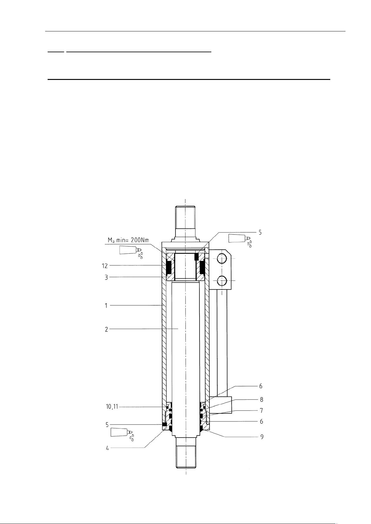
DCS05 / Z-Z05 - Cylinder - Picture/spare parts
Item
Pc.
Designation
Group
Order-No.
50
1
cylinder
E
2011001000
1
1
cylinder barrel
E
2011001001
2
1
piston rod
E
2011001002
3
1
piston
E
2011001003
4
1
guide nut
E
2011001004
5
2
set screw (! secured with screw adhesive)
A
5001007001
6
2
guide band
V
5002006002
7
1
rod seal
V
5002005002
8
1
rod seal
V
5002005001
9
1
scraper
V
5002007003
10
1
o-ring
V
5002004004
11
1
support ring
V
5002014002
12
1
piston seal
V
5002003006
13
1
seal set ( items 6 –12 )
S
2011001005

Clamshell grab
17
3.2
DCS1 / Z-Z1 with AG 5-2
3.2.1
DCS1 / Z-Z1 - Grab cpl. - Spareparts
Item
Pc.
Designation
Group
Order-No.
1
1
rotator
E
3007000119
2
1
frame
E
2002001001
3
2
steering
E
2004001001
4
1
clamshell with steering –300
E
2006001001
clamshell with steering –400
E
2006001002
clamshell with steering –500
E
2006001003
5
4
pin –frame/clamshell
V
3009035005
6
4
pin –cylinder/clamshell
V
3009035004
7
4
pin –steering
V
3009020001
8
4
bush –frame/clamshell
V
5003002103
9
4
bush –cylinder retainer
V
5003002108
10
4
bush –steering
V
5003002001
11
4
bolt
A
5001001014
12
4
washer
A
5001002084
13
4
bolt
A
5001001008
14
4
spring pin
A
5001005005
15
8
grease nipple
A
5003001001
16
1
bush set ( items 5 –15 )
S
2013001001
17
2
hose
A
5002010238
18
2
threaded adapter ( W )
A
5002001041
19
2
threaded adapter ( E )
A
5002001015
20
2
threaded adapter ( SW )
A
5002001089
21
4
threaded adapter ( VSTI )
A
5002001217
22
1
hydraulic set ( items 17 –20 )
S
2010001001
23
4
bolt –rotator/frame
A
5001001211
24
4
washer
A
5001002083
25
4
nut
A
5001006002
26
tooth
V
5004001002
27
bolt ( 2 pc./tooth )
V
5001001003
28
nut ( 2 pc./tooth )
V
5001006004
50
1
cylinder
E
2011001000
51
2
retainer
E
2001001001
52
2
washer
A
5001002021
53
2
nut
A
5001006005
70
1
hose protection
E
3005000001
71
4
bolt
A
5001001102
72
4
washer
A
5001002060
Clamshell grab
18
3.2.2
DCS1 / Z-Z1 - Grab cpl. -Picture
Clamshell grab
19
3.2.3
DCS1 / Z-Z1 - Cylinder - Picture/spare parts
A –Replacement part / E –Spare part / S –Set / V –Wearing part
Item
Pc.
Designation
Group
Order-No.
50
1
cylinder
E
2011001000
1
1
cylinder barrel
E
2011001001
2
1
piston rod
E
2011001002
3
1
piston
E
2011001003
4
1
guide nut
E
2011001004
5
2
set screw (! secured with screw adhesive)
A
5001007001
6
2
guide band
V
5002006002
7
1
rod seal
V
5002005002
8
1
rod seal
V
5002005001
9
1
scraper
V
5002007003
10
1
o-ring
V
5002004004
11
1
support ring
V
5002014002
12
1
piston seal
V
5002003006
13
1
seal set ( items 6 –12 )
S
2011001005

Clamshell grab
20
3.3
DCS2 / Z-Z2 with AG 5-2
3.3.1
DCS2 / Z-Z2 - Grab cpl. - Spareparts
A –Replacement part / E –Spare part / S –Set / V –Wearing part
Item
Pc.
Designation
Group
Order-No.
1
1
hose protection
E
3005000001
2
1
rotator
E
3007000119
3
1
frame
E
2002002001
4
1
clamshell carrier
E
2003002001
5
1
steering
E
2004002001
6
1
clamshell with teeth and clamshell carrier –
270
S
2007002001
clamshell with teeth and clamshell carrier –
300
S
2007002002
clamshell with teeth and clamshell carrier –
400
S
2007002003
clamshell with teeth and clamshell carrier –
500
S
2007002004
clamshell with teeth and clamshell carrier –
600
S
2007002005
7
2
pin –cylinder/frame
V
3009035003
8
6
pin - clamshell pivot/cylinder/clamshell
V
3009035002
9
2
pin –steering
V
3009035001
10
1
pin –frame/clamshell carrier
V
3009040001
11
2
bush –steering
V
5003002102
12
4
bush - frame/clamshell carrier
V
5003002101
13
1
folding split pin
A
5001004103
14
8
split pin
V
5001004003
15
12
grease nipple
A
5003001001
16
2
folding split pin
A
5001004104
17
1
bush set ( items 7 –16 )
S
2013002001
18
4
hose
A
5002010201
19
6
threaded adapter ( E )
A
5002001015
20
2
threaded adapter ( T )
A
5002001048
21
4
threaded adapter ( W )
A
5002001041
22
4
threaded adapter ( plug )
A
5002001217
23
1
hydraulic set ( items 18 –22 )
S
2010002001
24
tooth
V
5004001003
25
bolt ( 2 pc./tooth )
V
5001001203
26
nut ( 2 pc./tooth )
V
5001006006
27
4
bolt –rotator/frame
A
5001001206
28
4
washer
A
5001002083
29
4
washer
A
5001002060
30
4
bolt –hose protection
A
5001001102
31
4
threaded adapter ( plug )
A
5002001217
50
2
cylinder
E
2011002000
70
2
piston rod protection
E
2012002001
71
4
bolt –piston rod protection / cylinder
A
5001001007
72
4
washer
A
5001002085
This manual suits for next models
7
Table of contents


