matev FPS-LS J23/27 Installation instructions

matev GmbH
Nürnberger Str. 50
90579 Langenzenn
T +49 9101 9087 -0
F +49 9101 9087 -20
www.matev.eu
Version 05/2015
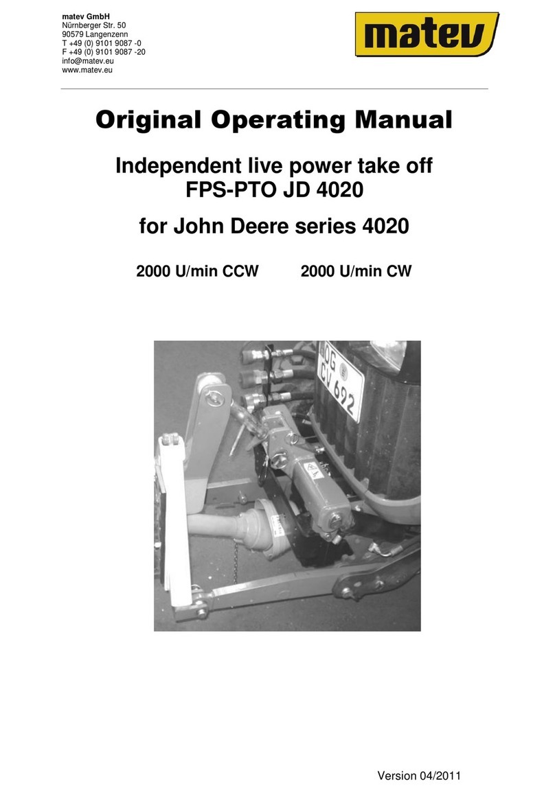
Original operating manual
Front Power System FPS-LS J23/27
for LS type J 23/27
Front Power System FPS-LS J23/27
Front PTO Shaft FPS-LS J23/27
Joystick Kit Dual, article no.
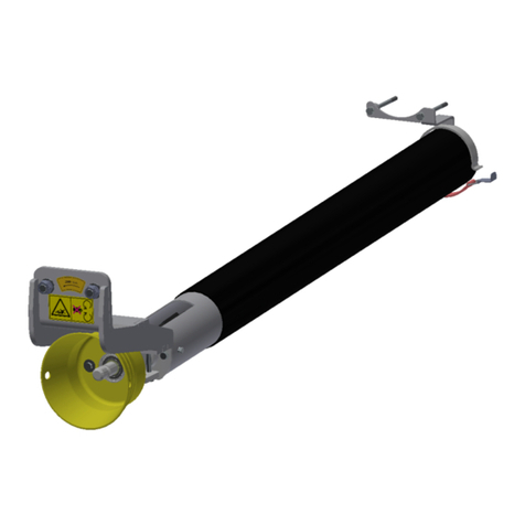
Universal Joint Shaft Guard

Contents
Table of contents
1About this operating manual....................................................................................3
2Safety.........................................................................................................................4
2.1 Intended use...............................................................................................................4
2.2 Qualifications of personnel..........................................................................................5
2.3 General safety notices ................................................................................................5
2.4 Special safety notices .................................................................................................5
3Installation.................................................................................................................7
3.1 Mounting the front power system ................................................................................7
3.1.1 Delivery status ............................................................................................................7
3.1.2 Mounting the front power system ................................................................................7
3.2 Mounting the front power system ................................................................................9
3.2.1 Installation of the joystick unit......................................................................................9
3.2.2 Mounting the front hydraulic extension kit .................................................................10
3.2.3 Attachment of the control device...............................................................................10
3.2.4 Connection assignments on the dual control valve....................................................11
3.2.5 Connecting the control device to the tractor hydraulic system...................................12
3.3 Mounting the front PTO shaft....................................................................................13
3.4 Mounting the universal joint shaft guard....................................................................14
4Operation.................................................................................................................16
4.1 Attachment variants for the coupling triangle.............................................................16
4.2 Coupling and uncoupling implements........................................................................17
4.3 Lowering safeguard for the front power system.........................................................17
5Maintenance............................................................................................................18
5.1 General information...................................................................................................18
5.2 Service......................................................................................................................18
5.2.1 Maintaining the hydraulic system ..............................................................................19
6Repair.......................................................................................................................19
7Disposal...................................................................................................................20
8Guarantee................................................................................................................20
9Technical data and accessories.............................................................................20
9.1 Technical data...........................................................................................................20
9.2 Accessories ..............................................................................................................20
10 List of illustrations..................................................................................................22
11 EC Declaration of Conformity ................................................................................23


About this operating manual
Page 3
1 About this operating manual
Dear customer!
Thank you for purchasing this implement, we appreciate your trust.
For optimal use of your new front power system, it is necessary to read this operating
manual completely and conscientiously, and to understand it.
To obtain the long service life for which matev products are known, careful and conscien-
tious maintenance is a strict requirement. However for proper maintenance of your front
power system it is strictly necessary that you have carefully read this operating manual.
Moreover it is not possible for matev to assume liability for damage that is attributed to
improper use or non-intended use of the front power system.
Keep this operating manual where it is easily accessible. This will enable you to refer to
important information and handling instructions as needed.
Listings with bullet points are marked as follows:
Text
Text
Text . . .
Handling instructions are marked in the sequence in which they should be executed, as
follows:
2. Text
3. Text
3. Text . . .
This implement is subject to change in the interest of technical progress. All
information, illustrations, and technical specifications represent the latest
status at the time this manual was published. The manufacturer reserves the
right to make changes at any time in the interest of technical progress.
However, we hereby state that this does not entail an obligation to extend
such changes to front power systems delivered earlier, or to the associated
accessories.

Safety
Page 4
2 Safety
Guidelines and instructions with which you must comply, are summarized in this section.
Personnel who install, operate and maintain the implements, must have read and under-
stood this operating manual.
2.1 Intended use
The front power system must only be mounted on tractors, type LS J 23/27, it is used for
accommodating small to medium-sized implements, such as snow blades, sweepers, etc.
and must only be connected and operated with such implements. Please note that you
must avoid overloading the front axle, even in heavy-duty implementation (e.g. snow re-
moval). The permissible axle load is specified in the appropriate documentation provided
by the tractor manufacturer.
Attention!
The front power system should not be charged with downward pressure via
the tractor's hydraulic system! For implements that contact the ground or
roll on the ground in operation, the tractor hydraulic system must be
switched to the float setting! Strictly comply with the manufacturer's rec-
ommendation!
The front power system is not suitable for lifting people or for use as a work
platform!
In addition, compliance with the service and maintenance guidelines is a component of
intended use. Moreover intended use includes exclusive use of original spare parts and
supplemental equipment, or use of such parts and equipment that meet the technical re-
quirements specified by the manufacturer.
All other uses are excluded.
Non-intended use causes:
Health hazards for the operator or for third parties
Damage to the tractor and the implements
Immediate invalidation of the guarantee
Environmental damage
To avoid accidents and to reduce the risk of accidents, the relevant accident prevention
regulations and the other generally acknowledged occupational health and safety and
road traffic regulations apply without limitation.
Changes to the front power system and/or the associated accessories invalidate the
guarantee and exclude any liability on the part of the manufacturer for damage due to the
changes.

Safety
Page 5
2.2 Qualifications of personnel
Only persons 18 years of age or older, or instructed persons should install, operate, and
maintain the implements. The operator must have read and understood this operating
manual.
2.3 General safety notices
General safety instructions are explained in this section. These safety instructions are
used in the subsequent chapters. In addition to the safety aspect, you will save money
and work time if you follow these safety instructions.
Danger!
Severe injury to the operator or third parties occurs.
Comply with the safety notice.
Attention!
Minor injury of the operator or third parties can occur. The tractor, the front
power system, or the environment can be damaged.
Comply with the safety notice.
Note!
Important, helpful tips or information for the operator.
Read this note. It facilitates your work.
Attention!
Injuries can occur.
Wear protective work clothing.
2.4 Special safety notices
The safety instructions specified in this chapter are also affixed as stickers on the imple-
ments.
Attention!
Danger of injury due to moving parts.
Remove the ignition key before performing maintenance tasks on the im-
plement.

Safety
Page 6
Attention!
Injuries can occur due to improper operation. The implement can be dam-
aged.
Read the operating manual all the way through.
Comply with the safety instructions.
Attention!
Injuries due to fluid escaping under high pressure.
Comply with the notice in the operating manual.
Attention!
Danger of crushing due to moving parts.
Never reach into the crushing hazard danger zone if parts are moving or can
move.
Comply with the notice in the operating manual.
Attention!
Increased risk of accident due to rotating PTO shaft.
Do not enter the work area of the PTO shaft when it is rotating.
For your own safety do not wear any loose clothing, belts, or any other
loose items. Switch off the implement. Wait until all machine parts have
come to a standstill before converting or servicing the implement.
Attention!
Check all threaded unions prior to using the implement and after using the
implement. Loosened connections must be re-tightened.
Damage can occur.

Installation
Page 7
3 Installation
Danger!
Severe injury to the operator or third parties occurs.
Switch off the tractor and remove the ignition key before mounting or dis-
mounting the implements.
Note!
Enter the vehicle ID number of the front power system in section 6, page 19
of this operating manual.
3.1 Mounting the front power system
3.1.1 Delivery status
Fig. 1: Lifter unit with hydraulic cylinder
3.1.2 Mounting the front power system
1. Position the attachment bracket shown in Fig. 2 correctly in front of the tractor.
Fig. 2: Attachment bracket

Installation
Page 8
2. Bolt the attachment bracket to the tractor frame on both sides with 2 screws on the
front and 4 screws on the rear (see Fig. 3).
Fig. 3: Fastening on the tractor frame
3. Then hook the front power system into the bearing bracket and secure it with the
arrest bolts shown in the Fig. below.
Fig. 4: Front power system
Threaded unions
Upper hook-in point
Arrest bolt

Installation
Page 9
3.2 Mounting the front power system
(article no. 131 7237)
3.2.1 Installation of the joystick unit
1. Mount the holder of the joy stick unit, as shown in Fig. 5, on the floor panel, and on
the frame of the tractor.
Fig. 5: Fastening position of the joystick holder
2. Cut out a hole, 30 mm in size, as shown in Fig. 6 for the cable pulls.
Fig. 6: Cable pull passage
Fastening points
Opening for cable pulls

Installation
Page 10
3.2.2 Mounting the front hydraulic extension kit
Fig. 7: Mounted front hydraulic kit
3. Bolt the hydraulic system console onto the right side of the attachment bracket. To
do this, use the two screws M12 x 40 mm already available on the front power sys-
tem.
Fig. 8: Hose guide
4. Now mount the hydraulic couplings on the console and lay out the hydraulic lines
to the connections of the control device.
3.2.3 Attachment of the control device
1. Fasten the holder for the control device, as shown in Fig. 9, with the aid of the pro-
vided M8 screws behind the right rear tire, in the direction of travel. Fasten the
holder for the control device with the two available M12 screws. Drill a hole with M8
thread, as shown in Fig. 10.
Black (lower the front power system)
Green (lift the front power system)
Blue (pivot to the right)
Red (pivot to the left)

Installation
Page 11
Fig. 9: Attachment position of the control device
Fig. 10: Bore position
3.2.4 Connection assignments on the dual control valve
A: Feed connection (hydraulic pump)
Green/black: Front power system (lifting/lowering)
Red/black: Pivoting (left/right)
B: Pressureless return (tank)
C: Pressure continuation
D: Cable pull / joystick connection (pivoting)
E: Cable pull / joystick connection with float position (lifting / lowering)
1. Note that the hoses, GE threaded unions, and angle bracket threaded unions must
be mounted before the control device is mounted. Retroactive installation is only
possible with significant difficulty.
Control device
Holder
Holder
Bore
M8

Installation
Page 12
Fig. 11: Control device connection assignment
2. Now connect the joystick and the control device to the cable pulls, in accordance
with the connection descriptions of the control device in Fig. 11. Then, at a suitable
point, fix the hoses in place with cable ties.
3.2.5 Connecting the control device to the tractor hydraulic system
When mounting the control device, it is connected to the tractor hydraulic system at the
connection points shown in Fig. 12.
Fig. 12: Tractor hydraulic system connections
D Blue (pivot to the right) C
Green (lift)
Black (lower)
A
E
Red (pivot to the left)
B
Holder Control block
A
C

Installation
Page 13
3.3 Mounting the front PTO shaft
(Optionally available, article no. 131 7238)
1. Screw the drive shaft onto the attachment bracket of the front power system from
the rear, in accordance with the Fig. below. To do this, use the three provided
M8x150 mm screws.
Fig. 13: Drive shaft bolted on
2. Use the universal joint shaft to connect the front PTO shaft with the mid-mount
PTO shaft.
3. To conclude, fasten the protective pot on the attachment bracket from the front with
two M6 screws.
Fig. 14: Mounted protective pot
Attachment
bracket
Drive shaft

Installation
Page 14
3.4 Mounting the universal joint shaft guard
(Optionally available, article no. 131 7239)
Fig. 15: Rear universal joint shaft guard holder
1. Fasten the rear universal joint shaft guard holder shown in Fig. 15 below the mid-
mount PTO shaft on the tapped bores that are already available.
2. Next, mount the front universal joint shaft guard holder on the drive shaft. To do
this, use the fastening screws of the drive shaft
Fig. 16: Front universal joint shaft guard holder
3. Guide the universal joint shaft into the black protective tube and connect the front
PTO shaft with the mid-mount PTO shaft.
4. In the front area the protective tube is fastened on the universal joint shaft guard
holder with the screws shown in the Fig. below.
Fastening points

Installation
Page 15
Fig. 17: Front protective tube fastening
5. In the rear area the protective tube is fastened via the tension strap.
Fig. 18: Tension strap fastening of the protective tube
Fastening screw M6

Operation
Page 16
4 Operation
Attention!
Before starting up the implement, read the instructions on safety and han-
dling for operation of the entire implement and connection to the tractor. In
addition, prior to start-up you must ensure that the vehicle meets the re-
quirements specified in the German Road Traffic Vehicle Licensing Act.
The front power system should only be placed in service if all safety devices
are attached and fully functional. Prior to starting work the operator must
familiarize himself with the device and ensure for himself that the entire de-
vice is operationally reliable.
Moving objects and fixtures, (ropes, chains, linkage, etc.) must be adequate-
ly secured before transport or driving on public roads to exclude the danger
of accident or hazards to third persons.
4.1 Attachment variants for the coupling triangle
Fig. 19: Coupling triangle
You can make four different settings on the coupling triangle (see Fig. 27 in this regard).
Position the bolts in the appropriate bores to achieve the desired setting.
Standard
Couple the triangle in points A and C.
Standard with stronger take-up
Couple the triangle in points B and C.
Lift increased by 45 mm
Couple the triangle in points B and D.
Lift increased by 45 mm with stronger take-up
Couple the triangle in points A and D.
B
A
D
C

Operation
Page 17
4.2 Coupling and uncoupling implements
Note!
Comply with the axle loads specified by the tractor manufacturer.
1. Drive the tractor forward in front of the implement.
2. Lower the front power system hydraulically.
3. Drive slowly toward the implement until the coupling triangle of the tractor is under
the coupling triangle of the implement.
4. Slowly lift the front power system until the implement is slightly lifted.
5. Secure the implement with the appropriate triangle locking mechanism. The trian-
gle locking mechanism depends on the type of implement.
4.3 Lowering safeguard for the front power system
Note!
Use the lowering safeguard for:
–Driving on roads
–Driving between work locations
–Performing cleaning and maintenance tasks
Fig. 20: Lowering safeguard, shown in unlocked position
6. Lift the front power system.
7. Remove the spring cotter pin on the arrest bolt of the lowering safeguard and slide
the lowering safeguard over the bolt. Then secure the lowering safeguard by insert-
ing the spring cotter pin. The Fig. below shows the locked lowering safeguard.
Lowering safeguard
Arrest bolt of the
lowering safeguard

Operation
Page 18
Fig. 21: Lowering safeguard shown locked
Note!
Strictly avoid lowering the front power system via the tractor's control lever
when the lowering safeguard is locked.
Parts of the front power system could be damaged!
5 Maintenance
5.1 General information
Attention!
Personal injury or damage to the tractor and the implements can occur.
Before each use check all safety-relevant parts, the hydraulic connections,
and all threaded unions.
5.2 Service
Attention!
Danger of injury due to moving parts.
Remove the ignition key before performing maintenance tasks on the im-
plement.
After 25 operating hours, at the start of the season, or after a longer standstill period:
Grease the moving parts of the device
Grease the bearing of the bracket on the PTO shaft drive.
Grease the lowering safeguard
Grease the arrest bolt
Check the seat, status and seal of the hydraulic lines
Before and after each use, check all threaded unions for firm seat and re-tighten them if
necessary.
Lowering safeguard

Disposal / guarantee / technical data and accessories
Page 19
Attention!
Repairs on parts that are under tension (springs, pressure accumulators)
require adequate skills and prescribed tools, and should only be performed
by specialists.
Note!
Replace any worn or no longer functioning protective device!
Note!
Only use original matev spare parts.
5.2.1 Maintaining the hydraulic system
Attention!
The hydraulic system is under high pressure.
Escaping fluids (hydraulic oil) can penetrate the skin and cause severe inju-
ries.
Attention!
Strictly ensure that you switch off the engine and de-pressurize the system
before executing tasks on the hydraulic system.
Regularly check the hydraulic lines and replace them if there is damage or signs of
aging.
6 Repair
If there are faults, problems, or other indications of malfunction, contact
your sales consultant or contact the manufacturer directly:
matev GmbH
Nürnberger Str. 50
90579 Langenzenn
Tel. (switchboard): 09 101/90 87-0
Enter the article number and the VIN number here.
This information is on the type plate of the device.

Repair
Page 20
Article number:...................................................................
Chassis number:................................................................
7 Disposal
The implements must be disposed of in accordance with the applicable regulations of the
municipality or the country.
Take the parts to the collection points for residual waste, special waste, or recycle them
depending on material.
matev GmbH does not provide any disposal services.
8 Guarantee
The General Terms & Conditions of matev GmbH provide information on the guarantee
conditions.
matev GmbH
Nürnberger Str. 50
90579 Langenzenn
9 Technical data and accessories
9.1 Technical data
Front Power System FPS-LS
J23/27
Data
Hydraulic cylinder
One double-acting cylinder arranged on the side
Lift force
Do not exceed the permissible axle loads of the vehi-
cle!
Lift-out height
255 mm
Coupling triangle and tension springs
Can be removed for frontloader attachment
Weight
50
9.2 Accessories
Accessories
Order number
Joystick kit dual
131 7237
Front PTO shaft
131 7238
Universal joint shaft guard
131 7239
Table of contents
Other matev Tractor Accessories manuals

matev
matev SRM-SF 140 Installation instructions

matev
matev FPS-FKH-NH Boomer 35 MJ 2021 User manual

matev
matev FPS-FKH-Kioti CX 2510 User manual

matev
matev FPS-FZW-Kioti CS 2520 User manual

matev
matev FPS-FKH-Kioti CS 2520 User manual

matev
matev SRM-VP 130 Installation instructions

matev
matev SRM-FB 130 Installation instructions

matev
matev FPS-PTO JD 4020 Installation instructions

matev
matev SCA-130 User manual

matev
matev FPS JD-2036R User manual