Prodew FogMist Track User guide

REV - MAR 2016
toll free help line: 866.677.6339
engineering & parts: 770.420.3060
www.prodew.com | sales@prodew.com
System Installation Manual
FogMist™ Track
System for Produce Cases


Table of Contents
If there is any information in this manual that is unclear, please let us know so we can revise future editions.
Contact our Customer Service department with your suggested edits: sales@prodew.com or 770.420.3060
Packing List 3
Utility Requirements 4
Quick Connect Fitting Assembly 5
System Layout 6
Air Compressor Kit Diagram 7
Track Breakdown 8
Track Mounting Options 9
Installation Instructions 10 - 11
Start-up Procedure 12
Timer Settings 13
System Warranty 14

Page 3
Quantity Description Images
1 Timer Box with Transformer and 110V Plug
1 Solenoid Box
VARIES FogMist™ Track Line
1 Air Compressor Kit
1 Sediment Filter (5 Micron) with Ball Valve
VARIES 3/8in Air/Water Supply Polypropylene Tubing
VARIES 5/8in Corrugated Tubing
VARIES 8in Zip Ties
VARIES Track Cover
VARIES Clamp Lock
Packing List

Page 4
Utility Requirements
Water Power Drain
• Dedicated water supply:
1/2in female NPT adapter
with ball valve
• Easily accessible and near
the case
• Minimum inlet pressure of
30 PSI
• 2-plug outlet:
110/220VAC
60/50Hz
20Amp
• Easily accessible and near
cases or location of control
box
• Floor drain:
Minimum 3/4in for waste
water or a 1/2in drain pipe
• Easily accessible and near
cases or location of control
box
THE FOLLOWING MUST BE IN PLACE BEFORE OUR INSTALLERS ARRIVE ON LOCATION

Page 5
Quick Connect Fitting Assembly

Page 6
System Layout
4
1
2
5
3
ITEM
NUMBER PART NUMBER DESCRIPTION QUANTITY
1 HTIM001-110C10 Timer, 110VAC - Premium 1
2 HSOLBX-PRM-A-FOG Humidity Solenoid Box - Premium 1
3 HCOM001-2HD-FOG Air Compressor, Double Head, 110VAC 1
4 FMTRC38-4BLK FogMist™ Track, 4ft - Black 1
5 2FIL-ENCAP-S10-05 Filter, Sediment 10in - 5 mic 1

Page 7
5
4
3
2
1
6
8
9
7
10
ITEM NUMBER PART NUMBER DESCRIPTION QUANTITY
1 2GAU006 Gauge 1.5 inch 1/4 inch NPT, 0-160 1
2 2PBSHM14F18-B Bushing, 1/4 inch M x 1/8 inch F - Plastic 1
3 2PMCQ38M14 M Con, 3/8 inch QC x 1/4 inch MPT 1
4 2AFIL-INL14-5MIC Air Filter 1/4 inch FNPT 5 mic 1
5 2MSTF14F14M14 Straight Tee 1/4 inch, MTL 1
6 1COM002 Air Compressor, Dbl Hd, 110VAC 1
7 2FCVAL-M14 Air Flow Control Valve 1/4 inch NPT 1
8 3CLPHUM003 Suction Cup, w/ 8-32 MS Insert 4
9 2AFIL003 Air Intake Filter 1/4 inch NPT 1
10 1WIR050 Wire, 16/3 Extension Cord 1
Air Compressor Kit Diagram

Page 8
Track Breakdown
7
5
2
1
8
3
4
6
ITEM
NUMBER PART NUMBER DESCRIPTION QUANTITY
1 2PURQ38Q14 Poly, Union Red 3/8in Q x 1/4in Q 2
2 2P2WDIVQ6-2XQ6 2-Way Divider, 6mm Q-2 x 6mm QA2 10
3 2VALQ6 Straight Valve 6mm x 6mm 4
4 FMSPR-4W6A-BL38T Spray Head, FogMist™ 4mm x 6mm Stem 4
5 3CLP388B Clamp, 388 - Black 1
6 3CLPCOV03-B C-Clamp Cover 9.75in 4
7 2PSP6-R Red Stem Plug 2
8 2TUB6O-4I-B Tubing, 6mm OD Poly - Black _____

Page 9
Track Mounting Options

Page 10
Instructions Images
STEP 1
• Mount the mist control box, air compressor, and timer box
at the center of the area being misted on top of the case.
• Other mounting locations can be used.
STEP 2
• Mount the clamp lock into the case ceiling in the area to
be fogged with the provided screws.
• Preferably inside the air curtain.
• Use the Track Mounting Options on page 6 for location
ideas.
STEP 3
• Spread the lines across the area which needs fogging.
• Use 3/4in tubing on the track line to hold the lines into the
clamp (try not to twist the lines as you install).
• For two or more sets of lines, the feed location should be
together for two lines.
• Once the lines are held in place, ensuring that all tubing
tsintotheclamp.
• Thecoverswilltinbetweenthenozzleandshutovalves
(some trimming and cutting may be needed for feed lines).
STEP 4
• Drill a hole for the feed lines in the case ceiling behind the
track (approximately 6in).
• Ensure that no water, air, electrical or refrigerated lines are
in the way.
• Insert a piece of corrugated tubing into the hole.
STEP 5
• Run the 6mm air and water tubing through the corrugated
tubing. Cut to length.
• Connect the 6mm air and water tubing to the 3/8in air and
water tubing using the 3/8in to 6mm reducing coupler.
Installation Instructions

Page 11
Installation Instructions (Continued)
Instructions Images
STEP 6
• Attach the 3/8in water tubing to the port labeled
“NOZZLE” on the mist control box.
• Run the 3/8in water tubing to the 7/8in drilled hole in the
case ceiling. Cut to length for the canopy.
• The feed’s under-shelf lines will be cut at shelf locations.
*Additionaltrackswilluse3/8inttingstosplitwaterand
air feeds.
STEP 7
• Locate the 3/8in black tubing. There should be a 1/2in
male connector attached to one end.
• ApplyTeontapetothemaleconnector.
• Thread the male connector into the city water supply ball
valve.
STEP 8
• Connect the 3/8in black tubing coming out of the water
supplytotheinlinelterattheballvalve.Cuttolength.
• Flushthelterintothedrainfor2minutes.
• Connecttheinlineltertothesolenoidboxportlabeled
“WATER INLET”.
• Straptheinlinelterandtheconnectinglinesusingzip
ties.
STEP 9
• Connect 3/8in black tubing to the mist control box port
labeled “DRAIN”.
• Runthedrainlinedowntowardstheoordrain.Cutto
length.
• Strap the 3/8in black tubing to the existing drain lines
using zip ties.
• Leave 1in air gap in between the 3/8in black tubing and
the drain to avoid contamination.
STEP 10
• Run the air line from the air compressor to the track using
the 3/8in tubing.
• Usea3/8into6mmreducingttingonthetracklineto
make the connection.

Page 12
Start-up Procedure
1. Plug in the air compressor(s) into the outlet on the timer box. Plug the timer’s 110V plug and transformer
into the city power supply outlet.
2. Ensure that you have water and power.
3. Conrmthateverythingispluggedinandconnected.
4. Turn on water valve and check the inlet pressure by looking at the solenoid box gauge. The pressure is
factory set to 30 PSI. Adjust the pressure by opening the solenoid box and rotating the black knob by
hand or screw driver. Increase the water pressure to increase fog density (See Image 1 below).
5. Set OFF TIME to its minimum (0.5 min) and ON TIME to maximum settings (2.5 min). Remove the stem
plugs from the air and water lines at the end of the line where the last nozzle is located.
(See Steps to Set the Timer - pg 10)
6. Flip the toggle switch on the timer box to ON position. The air compressor should start after 5 seconds.
Flush one cycle and then replace the plugs.
7. Check the air pressure by looking at the gauge on the air compressor. The air pressure should be 15-20
PSI (higher air pressure preferred, but do not exceed 20 PSI). If it’s not correct, adjust the air pressure
on the air compressor with the allen wrench (See Image 2 below).
8. Let the system run for several cycles until all nozzles are spraying.
9. Check for leaks and ensure proper mist pattern. Ensure all nozzles are spraying. If not, see
Troubleshooting Guide.
10.Set the timer to recommended settings (See Recommended Timer Settings - pg 10).
System is ready for use.
Image 1 Image 2
Page 13
• The recommended cycle times are preset at our manufacturing facility
• If repairs or changes have been made to the control box, pressure tank, or water feeds, we
recommendthatyouushthelinestoensurethatnoparticles,liquidTeon,Teontape,pipedope,
or any other foreign matter is present in the system.
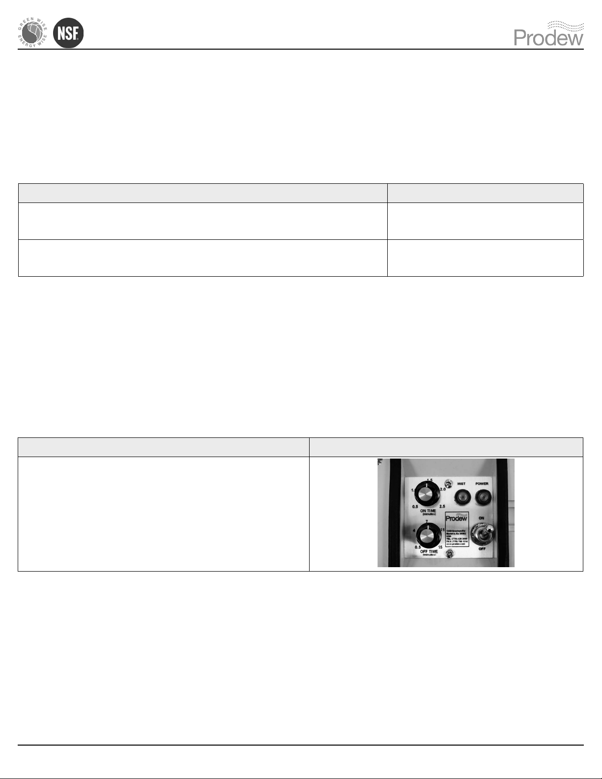
Instructions Images
• The “on time” is set by rotating the black knob
marked ON TIME.
• The“otime”issetbyrotatingtheblackknob
marked OFF TIME.
Steps to Set the Timer
Settings Time
ON TIME (Amount of time fog is being produced) 1.5 minutes
OFF TIME (Amount of time between fogging) 8 minutes
Recommended Timer Settings
Timer Adjustment
• The recommended settings are preset at our manufacturing facility.
• ONLY change the settings if there is too much or too little mist.
• Startwithadjustingtheotimerstandthentheontime.

Page 14
At Prodew, we are dedicated to providing innovative designs and well-made products
totourcustomers’individualneeds.Iftheproductyoupurchasefromusdoesnot
performtothedesignspecications,weaskfortheopportunitytomakeitright.
Ifyouarestillnotsatised,wewillmakeadjustmentsaccordingtoourLimitedWarranty
and Exclusion of Remedies Policy.
LIMITED WARRANTY AND EXCLUSION OF REMEDIES
Perishable control equipment and component parts distributed by Prodew, Inc., its
suppliers and agents, as well as new material furnished hereunder, is warranted against
any defect in materials or service in accordance with factory recommendations providing
that a claim, therefore, is made in writing within the limit set forth as 365 days from the
date of invoice for parts and 90 from the date of invoice for labor, and that either Prodew,
Inc. or its Authorized Service Agency’s examination, shall disclose to the Distributor’s
satisfaction to be thus defective. PRODEW INC.’S OBLIGATION ON ANY CLAIM
IS LIMITED TO REPLACEMENT OR REPAIR OF THE DEFECT OR MATERIAL F.O.B.
FACTORY.
PretreatmentmayadverselyaecttheperformanceofProdew,Inc.’sperishablecontrol
equipment. Prodew, Inc. takes no responsibility for damage resulting from unapproved
pretreatment equipment and/or inappropriate maintenance of said equipment.
THERE ARE NO WARRANTIES, EXPRESSED OR IMPLIED, OF ANY NATURE
WHATSOEVER, INCLUDING THE WARRANTY OF MERCHANTABILITY, EXCEPT AS
SPECIFICALLY SET FORTH HEREIN.
Except as stated above, Prodew, Inc., its suppliers, and agents will not be liable for
any loss, injury, or damages to persons or property resulting from failure of defective
operation of any material, equipment, or installation furnished hereunder or delay in
performance of this agreement, nor will it be liable for direct, indirect, special, incidental,
or consequential damages of any kind sustained from any cause. This writing expresses
the entire agreement, and no other agreement, statement, or representation shall be
binding unless reduced to writing.
FogMist™ System Warranty

toll free help line: 866.677.6339
engineering & parts: 770.420.3060
www.prodew.com | sales@prodew.com
Water, Air & Energy Innovations
Other manuals for FogMist Track
1
Table of contents
Other Prodew Lawn And Garden Equipment manuals

Popular Lawn And Garden Equipment manuals by other brands

Sunforce
Sunforce SOLAR user manual

GARDEN OF EDEN
GARDEN OF EDEN 55627 user manual

Goizper Group
Goizper Group MATABI POLMINOR instruction manual

Rain Bird
Rain Bird 11000 Series Operation & maintenance manual

Cub Cadet
Cub Cadet BB 230 brochure

EXTOL PREMIUM
EXTOL PREMIUM 8891590 Translation of the original user manual


Vertex
Vertex 1/3 HP Maintenance instructions

GHE
GHE AeroFlo 80 manual

Land Pride
Land Pride Post Hole Diggers HD25 Operator's manual

Yazoo/Kees
Yazoo/Kees Z9 Commercial Collection System Z9A Operator's & parts manual

Premier designs
Premier designs WindGarden 26829 Assembly instructions

Snapper
Snapper 1691351 installation instructions