Prodew FogMist Track User manual
FogMist™ Track
Installation Manual for Produce Canopy
rev June 2017

www.facebook.com/Prodew.Inc

Table of Contents
Package Contents 5
Utility Requirements 6
System Layout 7
Air Compressor Kit Diagram 8-9
FogMist™ Track Breakdown 10
System Installation 11 - 15
Start-Up Procedures 16 - 19
Timer Settings 20
System Warranty 21
Having trouble understanding our instructions?
Contact our customer service
department with your questions.
sales@prodew.com

4
Quick Connect Fitting Assembly

5
Package Contents
Solenoid Box
(FMSOLBX-PRM38)
Timer Box
(HTIM001-110-CLDUL)
Phosphate Filter (5mic)
(2FIL-EC-S10-2038-P)
FogMist™ Clamp Lock
(3CLP388B)
Stainless
Steel Screws
(3FAS002)
Air Compressor Kit
(HCOM001-2HD-FOG)
FogMist™ Track
(FMTRC38-―-1B)
8in Zip-Ties
(3TIE7)
FogMist™ Track Cover
(3CLPCOVO―-B)
3/8in Clips
(3CLPCAB-38)
3/8” Tubing
(2TUB12O-38I-B)
1/2” x 6” Protective
Corrugated Tubing
(2TUB-COR-12ID-B-SLT)
3/8” x 1/4”
Splitter
Connection
(need part number)
Male Connector,
3/8” QC x 1/2”
MPT
(2PMCQ38M12)
3/4” Tubing
(2TUB340-58ID-B)
Stainless
Steel Screws
(FAS001)
6
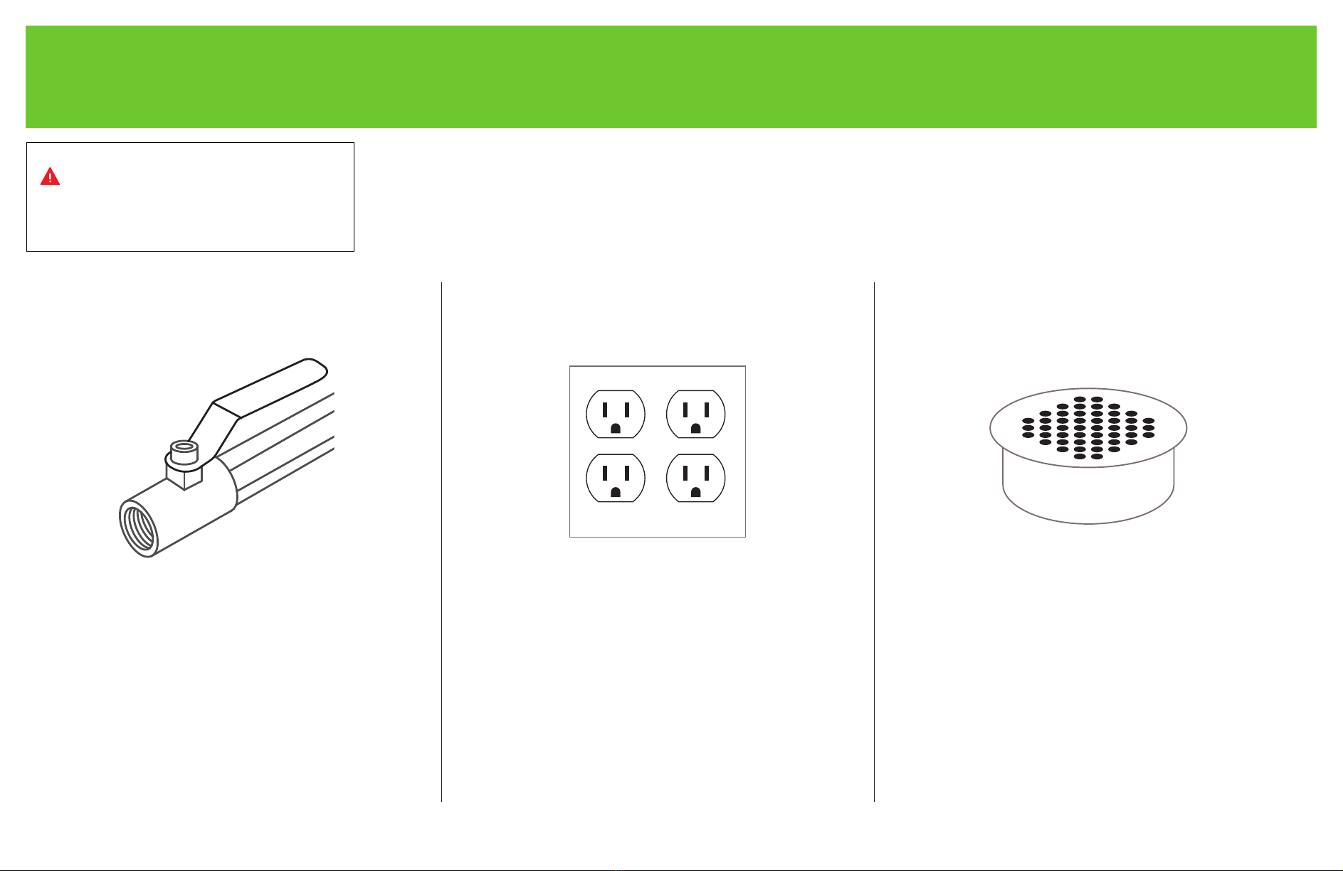
Utility Requirements
• 1/2in female NPT
adapter with ball valve
• Minimum inlet pressure
of 30 PSI
• Easily accessible under
the display case
Water Supply
• 110/220VAC
60/50Hz
20Amp
• Easily accessible under
the display case
4-Plug Power Outlet
• Minimum 3/4in for
waste water or a 1/2in
drain pipe
• Easily accessible under
the display case
Floor Drain
IMPORTANT
These utility requirements must be in
place before installation can take place.

7
System Layout

8
Air Compressor Kit Diagram
HCOM001-2HD-FOG (Small Systems)
4
3
2
1
57
8
6
9
# PART NUMBER DESCRIPTION QTTY
1 2GAU007 Gauge 1.5'' 1/4NPT, 0-150 1
2
3
2PMCQ38M14 M Con, 3/8 inch QC x 1/4 inch MPT 1
4
2AFIL-INL14-5MIC Air Filter 1/4 inch FNPT 5mic 1
2MSTF14F14M14 Straight Tee 1/4 inch, MTL 1
5
6
1CON119 #10 Blue Nylon Ring Terminal
7
2FCVAL-M14 Air Flow Control Valve 1/4 inch NPT 1
8
3CLPHUM003 Suction Cup, w/ 8-32 MS Insert 4
9
1WIR050 Wire, 16/3 Extension Cord 1
5 1COM006 Air Compressor, Dbl Hd, 110VAC 1
# PART NUMBER DESCRIPTION QTTY # PART NUMBER DESCRIPTION QTTY# PART NUMBER DESCRIPTION QTTY
1CON111 Wire, Butt Connector 18-22 GA 2

9
FogMist™ Track for Produce Breakdown
ITEM #
PART # DESCRIPTION
1
2PURQ38Q14
Poly, Union Red 3/8Qx1/4Q
2
2P2WDIVQ6-2XQ6-C
2 Way Divider, 6mmQ-2 x 6mmQA2
3
2VALQ6 Straight Valve 6mm x6mm
4
4SPRFM-4W6A-BL38T Spry, Fog Mist 4mm x 6mm Stem
ITEM #
PART # DESCRIPTION
6
3CLPCOV03-B C Clamp Cover 9.75"
7
2PSP6-C
Red Stem Plug
8
2TUB6O-4I-B
Tub, 6mm OD Poly BK
5
3CLP388B Clamp, 388 BK
12
3 4
5
7
6
8

10
System Installation
4
2
IMPORTANT
Make sure to place the control box
near a power and water source.
FLUSH THE CITY WATER LINE FOR
3-4 MINUTES BEFORE CONNECTING
TO OUR WATER LINE.
Tools Required
Material Required
Tube Cutter
Drill
TeonTape
Misc Drill Bits
& Drivers
Adjustable
Wrenches
Chanel Lock
Pliers
Screw Drivers
1
3
Mount the mist control, air compressor and
timer box at the center of the area being
misted on top of the case.
(Other mounting locations can be used.)
OR
Air Curtain
Notch the clamp lock near the middle of the case where
the hole will be drilled to connect water and air lines.
Mount the clamp lock into the case ceiling in
the area to be fogged with the provided screws.
Decide where to mount the clamp lock onto the
case ceiling in the area to be fogged - preferably
inside the air curtain (can
also be placed outside of air
curtain).
11
System Installation
765
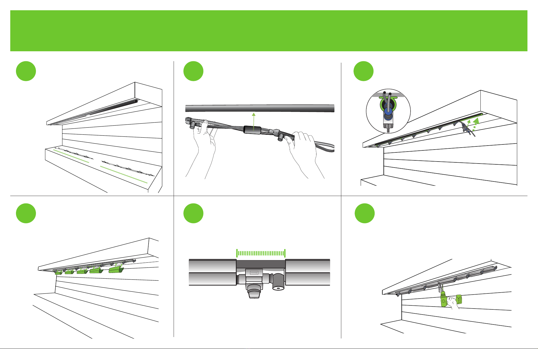
8910 Drill a hole for the feed lines in the case ceiling
behind the track (approximately 6in).
The hole should be drilled in the middle of the
case where the two lines of track meet.
Ensure that no water, air, electrical or
refrigerated lines are in the way.
When placing the covers, do not place
over the nozzles and shut-off valve. Make
sure to leave a gap as to not obstruct
valve and mist.
Snap the covers over the lines onto the
mounting clamp. The covers will t between
the nozzle and shutoff valves on the
exposed tubing (some trimming may be
needed for proper t).
Using 3/4in tubing on the track line, insert
the lines into the clamp. (Try not to twist the
lines as you install.)
Spread the lines across the area to be
fogged, starting from the center point and
going in each direction.
Once the lines are in place, ensure that all
tubing ts into the clamp.

1212
System Installation
131211
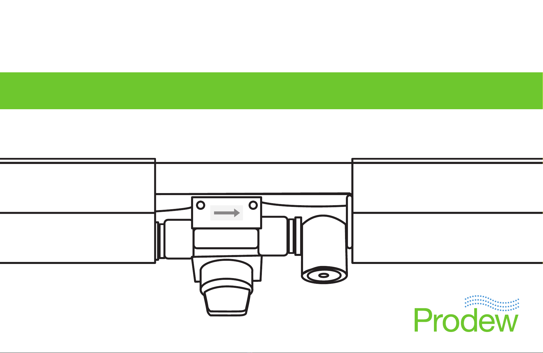
14 15 Connect the Y-divider ttings to the tubing from
couplers.
1/4”
WATER
1/4”
AIR
CASE CEILING
16
Insert a piece of corrugated tubing into
the hole to protect the lines.
Remove the couplers from the ends of the
track liners to be able to guide lines through
the corrugated tubing.
CASE CEILING
Once the corrugated tubing is set into place
it’s time to connect track lines to the controls.
Run the 6mm air and water lines through the
corrugated tubing. Cut to length if needed.
Re-attach couplers. Insert a 1/2in piece of
3/8in tubing into each coupler to connect to
the Y-divider tting. Be sure that both
air lines are going
to one Y, and
both water lines
are going to the
other Y.

13
System Installation
19
20
Run 3/8in air tubing from the air compressor
to air Y-divider.
Cut to length.
21
3/8”
WATER
3/8”
AIR
1/4”
WATER
1/4”
AIR
CASE CEILINGCASE CEILING
Connect the 3/8in air tubing from the
air compressor to the Y-divider with the
6mm air lines.
Connect the 3/8in water tubing from the mist
control box to the Y-divider with the 6mm
water lines.
Attach the 3/8in water tubing to the port
labeled “NOZZLE” on the mist control box.
Run 3/8in water tubing to water
Y-divider.
Cut to length.
17 18
Your lines should look like this after they’re
runt, cut to length, and connected.
3/8”
WATER
3/8”
AIR
1/4”
WATER
1/4”
AIR
CASE CEILINGCASE CEILING
22

14
Connect the 3/8in black tubing from the
water supply to the inline lter at the ball
valve. Cut to length.
Flush the lter into the drain for 2 minutes.
FLUSH THE CITY WATER LINE FOR
3-4 MINUTES BEFORE CONNECTING
TO OUR WATER LINE.
Thread black tubing
(water inlet and drain kit)
Run the drain line to the oor drain. Cut to
length.
Strap the 3/8in black tubing to the existing
drain lines using zip ties.
Leave 1in air gap between the 3/8in black
tubing and the drain to avoid contamination.
Connect 3/8in black tubing to the mist
control box port labeled “DRAIN”.
Connect the inline lter to the mist control
box port labeled “WATER INLET”.
System Installation
23 24 25
22
2726
Fill all voids around the corrugated tubing
with silicone to avoid leaks.

15
Start-up Procedures
4
21
3
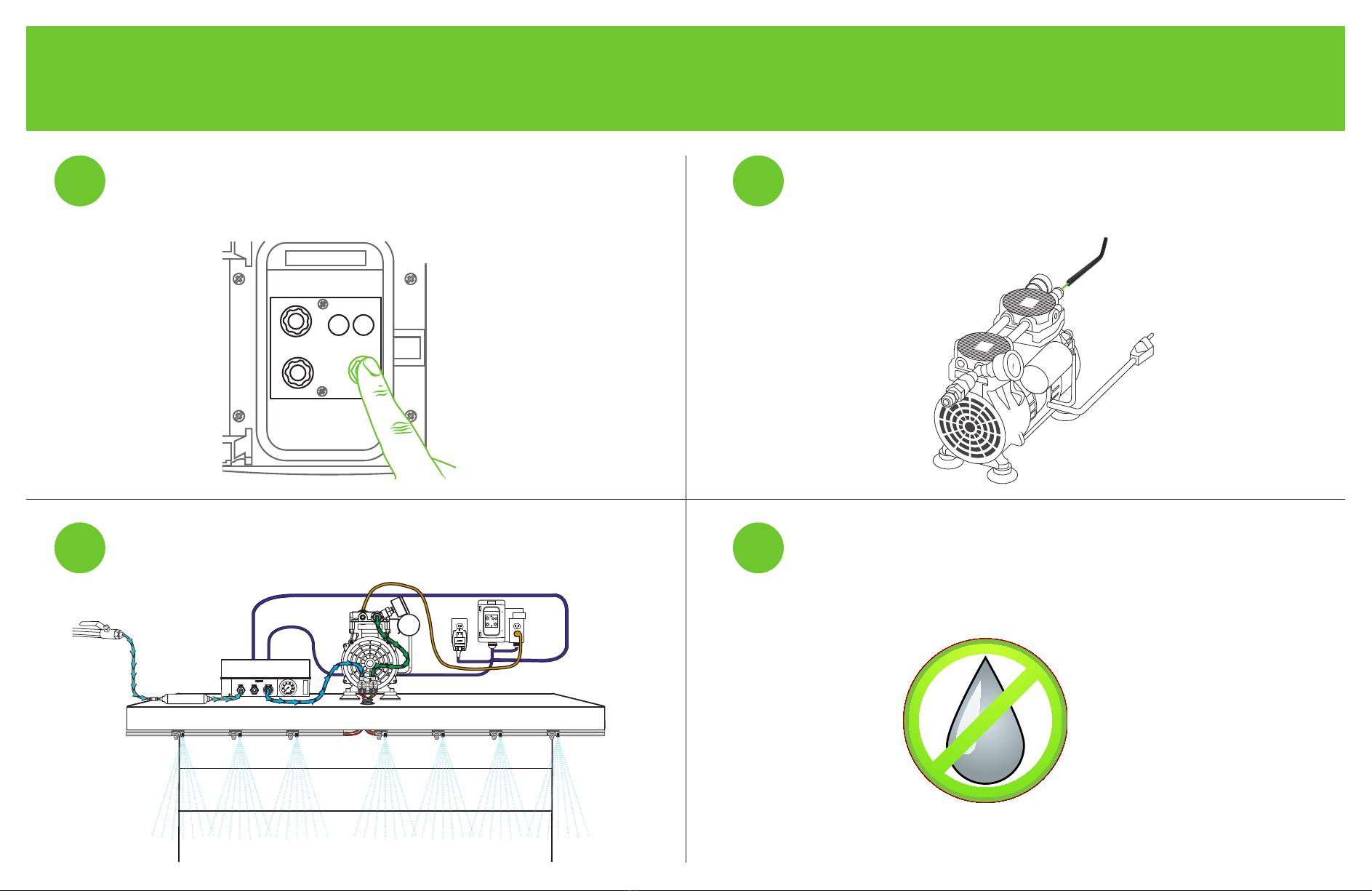
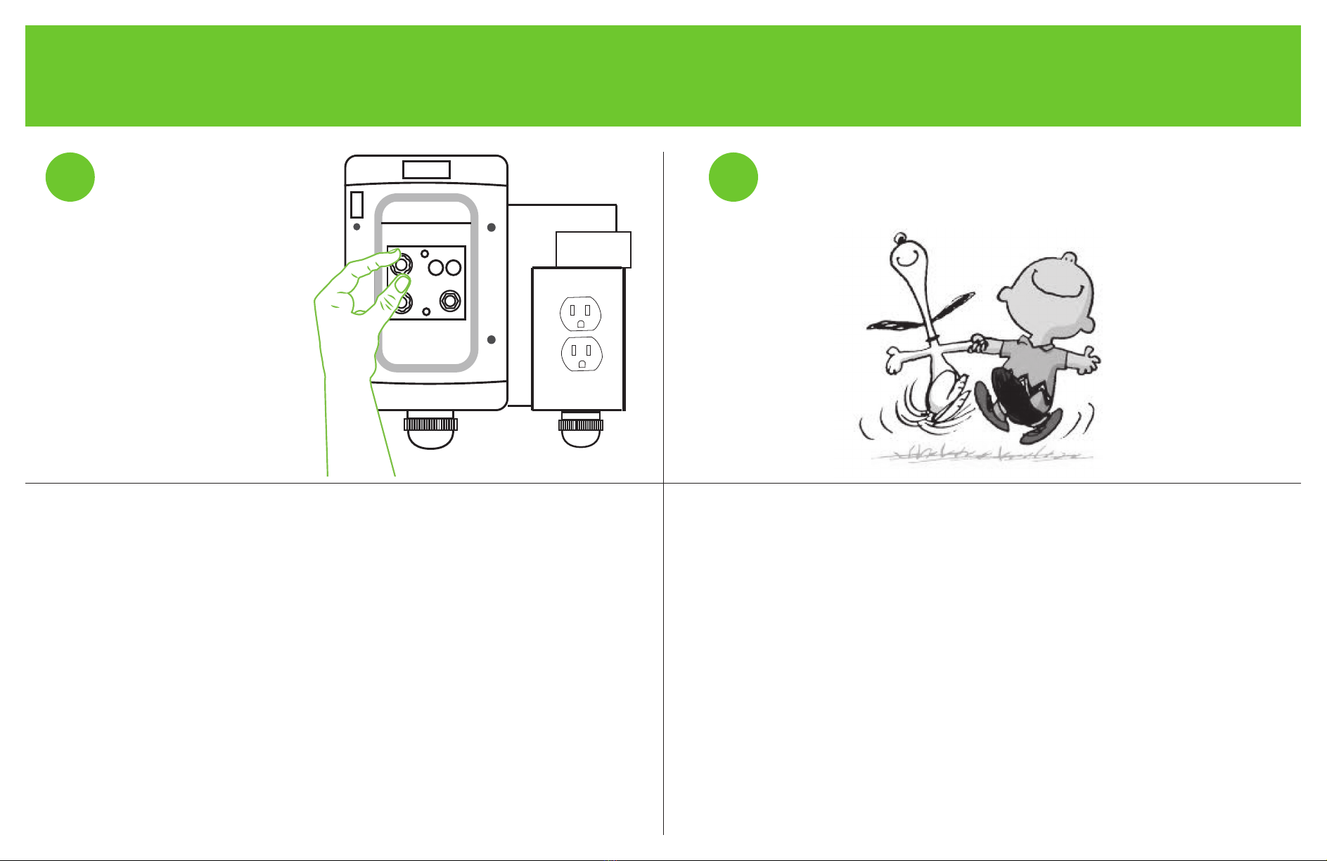
Plug the air compressor(s) into the outlet on the timer box. Plug the
timer’s 110V transformer into the city power supply outlet.
Ensure that you have water and power. Conrm
that everything is plugged in and connected.
Turn on water valve and check the inlet pressure by looking at the
solenoid box gauge. The pressure is factory set to 30 PSI. Adjust the
pressure by opening the solenoid box and rotating the black knob by hand
or screw driver. Increase the water pressure to increase fog density.
Set OFF TIME to its minimum (0.5 min) and ON Time to
maximum settings (2.5 min). Remove the stem plugs from
the air and water lines at the end of the line where the last
nozzle is located.
(See Steps to Set the Timer - pg 20)
20
30
40
60
80
100
120
140
150
16
Start-up Procedures
8
65
7
Flip the toggle switch on the timer box to ON position. The air
compressor should start after 5 seconds. Flush for one cycle and
then replace the stem plugs.
Check the air pressure by looking at the gauge on the air
compressor. The air pressure should be 15-20 PSI (higher
air pressure preferred, but do not exceed 20 PSI). If it’s not
correct, adjust the air pressure on the air compressor with
the allen wrench.
Let the system run for several cycles until all nozzles are spraying. Check for leaks and ensure proper mist pattern.
Ensure all nozzles are spraying. If not, see
Troubleshooting Guide.
1.5
1
0.5 2.5
2.0
MIST POWER
ON TIME
OFF TIME
7
4
0.5 1.5
11
ON
17
Start-up Procedures
9Set the timer to
recommended settings
(See Recommended
Timer Settings - pg 20).
Do a happy dance.
System is ready for use.
9

18
Timer Settings
• ON Time - 0.5 - 2.5 minutes
Duration of fog cycle.
• OFF Time - 1 - 15 minutes
Duration in between fog cycles.
Factory Presets
IMPORTANT
The factory presets are the
recommended settings for the system.
Only change the settings if there is
too much or too little fog.
The ON time is set by
rotating the black knob
marked ‘ON TIME’
The recommended cycle times are preset at our manufacturing facility.
If repairs or changes have been made to the system, we recommend that you
ushthelinestoensurethatnoparticles,liquidTeon,Teontape,pipedope,
or other foreign matter is present in the system.
The OFF time is set by
rotating the black knob
marked ‘OFF TIME’
1.5
1
0.5 2.5
2.0
MIST POWER
ON
OFF
ON TIME
(minutes)
OFF TIME
(minutes)
8
4.5
115
11.5
1.5
1
0.5 2.5
2.0
MIST POWER
ON
OFF
ON TIME
(minutes)
OFF TIME
(minutes)
8
4.5
115
11.5
FILTER CHANGE
SCHEDULE
for Phosphate Inline Filter
(2FIL-EC-S10-2038-P)
Water quality
PPM coming into
Solenoid Box
Filter
Change
Schedule
>100 quarterly
100 as needed
(monthly)
forinlinemeshlter
in the solenoid box
lter can be cleaned;
only needs to be replaced if
damaged or too clogged to clean
• unscrew cover and
remove mesh screen
• wash screen with a mild cleaner
• scrub with a soft brush if
necessary
• reinstall screen and securely
tighten cover

19
System Warranty
AtProdew,wearededicatedtoprovidinginnovativedesignsandwell-madeproductstotourcustomers’individualneeds.
Iftheproductyoupurchasefromusdoesnotperformtothedesignspecications,weaskfortheopportunitytomakeitright.
Ifyouarestillnotsatised,wewillmakeadjustmentsaccordingtoourLimitedWarrantyandExclusionofRemediesPolicy.
LIMITED WARRANTY AND EXCLUSION OF REMEDIES
Perishable control equipment and component parts distributed by Prodew, Inc., its suppliers and agents, as well as new material
furnished hereunder, is warranted against any defect in materials or service in accordance with factory recommendations providing
that a claim, therefore, is made in writing within the limit set forth as 365 days from the date of invoice for parts (not including nozzles)
and 90 from the date of invoice for labor, and that either Prodew, Inc. or its Authorized Service Agency’s examination, shall disclose to
the Distributor’s satisfaction to be thus defective. PRODEW INC.’S OBLIGATION ON ANY CLAIM IS LIMITED TO REPLACEMENT OR
REPAIR OF THE DEFECT OR MATERIAL F.O.B. FACTORY.
PretreatmentmayadverselyaecttheperformanceofProdew,Inc.’sperishablecontrolequipment.Prodew,Inc.takesno
responsibility for damage resulting from unapproved pretreatment equipment and/or inappropriate maintenance of said equipment.
THERE ARE NO WARRANTIES, EXPRESSED OR IMPLIED, OF ANY NATURE WHATSOEVER, INCLUDING THE WARRANTY OF
MERCHANTABILITY, EXCEPT AS SPECIFICALLY SET FORTH HEREIN.
Except as stated above, Prodew, Inc., its suppliers, and agents will not be liable for any loss, injury, or damages to persons or
property resulting from failure of defective operation of any material, equipment, or installation furnished hereunder or delay in
performance of this agreement, nor will it be liable for direct, indirect, special, incidental, or consequential damages of any kind
sustained from any cause. This writing expresses the entire agreement, and no other agreement, statement, or representation shall
be binding unless reduced to writing.
FILTER CHANGE
SCHEDULE

www.prodew.com
sales@prodew.com
770.420.3060 | 866.677.6339
1359 Gresham Road
Marietta, GA, 30066
Other manuals for FogMist Track
1
This manual suits for next models
1
Table of contents
Other Prodew Lawn And Garden Equipment manuals


