Prodif SIL06J User manual

Page 8
MARKING - TRACKING.........P3
SPARE PARTLIST................P4/5
EXPLODED VIEW.................P 5
GUARANTEE.......................P 6
SAFETY VALVE Certificate....P7
Page 1
OILLESS COMPRESSOR / AUTOLUBRICATED:
MANUAL
USE
MAINTENANCE
SYNOPSIS :
INSTALLATION AND SITE....................P2
INSTRUCTIONS, USE OPERATING......P2
FOR YOUR SECURITY ......................P 2/3
MAINTENANCE..................................P 3
FAULTS / SOLUTIONS.........................P3
STAMPOFTHERETAILER
A-NoticeSIL06J-YW400.pmd 2015-03-03 THISDOCUMENTISNOTCONTRACTUAL. Technicalcharacteristicsforinformation only. Subject tomodifications withoutadvance notice.
SIL06JSIL06J
SIL06JSIL06J
SIL06J
SIL06J
3 - FOR YOUR SECURITY
ÜThe air delivered by your compressor allows you
to use many tools, follow conditions, advice and
in certain cases RESTRICTIONS OF USE for air
tools using compressed air.
2 - INSTRUCTIONS, USES ADVICE
To obtain the best efficiency, please respect the
following indications:
- HORIZONTAL SETTING: the compressor must be
installed on a horizontal plane, 15 ° angle is
allowable.
- PLACE: Use the compressor indoors or under
shelter, do not expose it to the rain or near water
jets. Do not use the compressor in an explosive
atmosphere.
- VENTILATION: The compressor must be in a place
which allows ventilation, do not cover the
ventilation openings.
- TEMPERATURE: Use the compressor between
(+ 5°C and +35°C) (Otherwise, there are risks for
the electrical motor.)
- TENSION: Check that the sector tension and
tension indicated on the label are the same :
(Single phase:230 Volts - 50 Hz)
INSTALLATIONANDSITE
INSTRUCTIONS,USEADVICE
SECURITY
You have just bought your air compressor, it will
give you appreciable services.
Inflation: Tyres - Balloons - Swimming pools -
inflatable boats etc ......
Blowing - Dusting - Painting - Stapling…
Before using it, it is imperative to read ENTIRELY
the present NOTE.
1 - INSTALLATIONAND SITE
- ADJUSTMENT OF PRESSURE:
- AFTER USING:
ÜNever stop by disconnecting the electrical cable.
ÜNever leave the compressor power connected under
pressure.
ØSwitch the interruptor in "Off" position (Ref: A, Pict.1)
ØEmpty the tank ØDrain the tank (Ref: P, Pict.1)
ØDisconnect the electrical cable.
ÜAdjust the pressure of use and the consumption of
air to the characteristics of the tools you wish to
use.
(See the documentation provided with your tools).
ÜThe quantity of air consumed depends on the type
of tool used: do not use a tool consuming more
than 60% of the possibilities of your compressor.
ÜThe pressure controller is adjusted in factory and
needs no re adjustment.
ÜPressure gauge (Ref: C, Pict.1) indicates the
pressure inside the tank.
ÜPressure gauge (Ref: U, Pict.1) indicates the
useful exit air pressure.
To adjust the output of air pressure , it is necessary to
turn the pressure reducer button (Ref: B, Pict.1)
In clockwise direction to increase pressure, and
opposite to decrease it.
You must use the tool only when the pressure in the
tank is higher than the pressure of use of the tool.
ÜTo use your compressor correctly, only use it
intermittently, i.e. 60% of use for 40% of
downtime.
Beyond this limit, the engine risks overheating
problems.
- PRECAUTIONS TO PAINT:
If the electric motor and the interior of the pump are
dirty, your compressor life expectancy will be
reduced:
ÜIn order to avoid this problem, only move away
the compressor by lengthening the tube of your
tool.
-OPERATINGTIME:
Page 2 Page 7
- USING APNEUMATIC EXTENSION:
ÜFor pressures higher than 7 bar, use pipes
reinforced with steel braid.
ÜCheck that the compressor has not been
damaged during the transport.
ÜThe switch (Ref: A, Pict.1) must be in position
«Off».
ÜConnect in a socket-outlet:
- Of 16 Amps under 230V.
- Connected to the ground.
- Connected to a differential protection.
- USING AN ELECTRIC EXTENSION:
- BEFORE USE:
ÜPlease only use an extension if absolutely
necessary.
We recommend the following dimensions: 5 meters
maximum length with section of wire of 2,5mm ².
ÜToo small diameter wire sections and big lengths
would cause serious damage to the engine.
ÜIt is better to extend air pipe, which also will give
you stock of air. F.MURET
ThePresident
Buc the 2015-03-03
- Manufacturer's logo
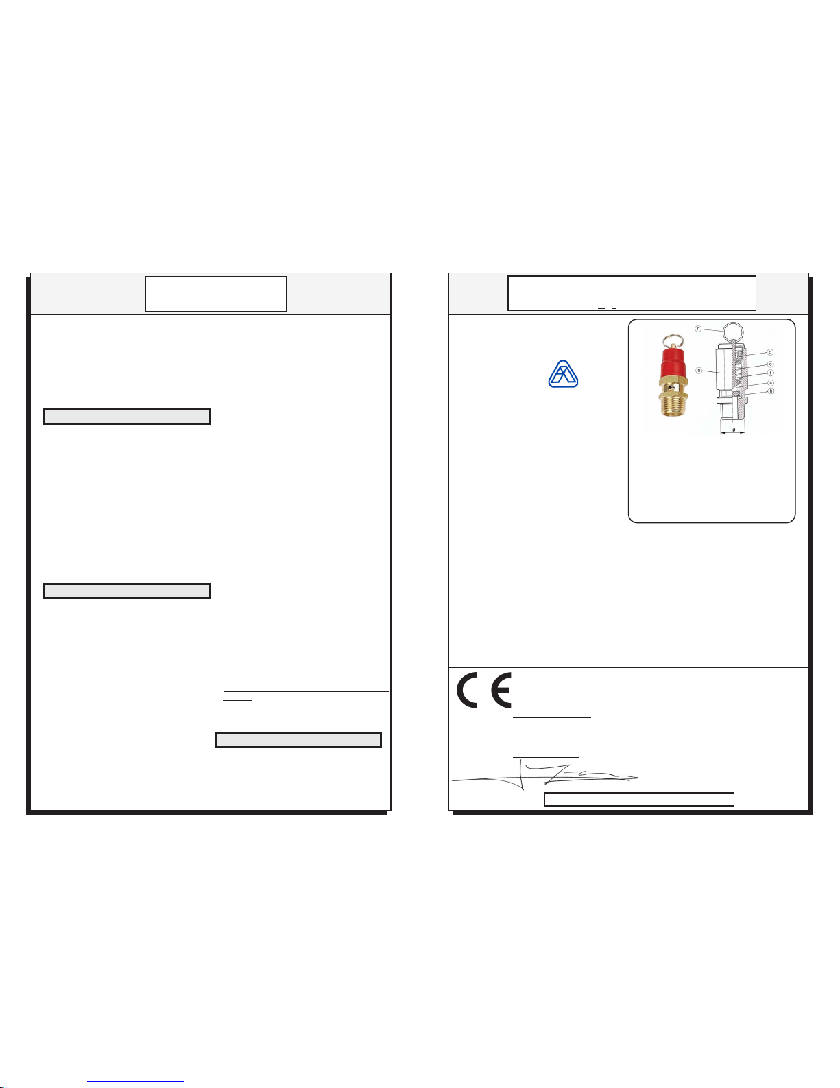
- PT = Setting pressure 8 bar
- Q = Maximum opening flow 1895 l/min
- Input threading : 1/4" gaz
- Input pressure rated : 25 bar
- Opening diameter : 6 mm
- Opening area : 28,26 mm²
- Fluid type : Compressed air
- Working temperature : NBR -10°C +90°C
- The used materials fit to good functioning according to the working conditions and the
aforementioned fluids.
- The technical data that identify the safety valve are indicated on the plate.
- The mechanical locking of the setting is obtained by the application of a glue-sealing (Loctite
270).
-The setting of the safety valve is secured by a final punching on the body of the safety
valve.
- Satisfactory results were obtained after the final check and after the hydraulic test carried
out at 37,5 bar.
- The setting of this safety valve, carried out at T°=20°C, garantees an opening beginning
and a mawimum outflow according to the indicated values in the technical characteristics.
- These values are recalled on the identification sticker set on the security valve.
- Identification of the marking: PT= Setting pressure D= Opening diameter and Q= Flow
to full opening for the compressed air.
AUTOMATICSAFETYVALVECERTIFICATE
FOR SIMPLE PRESSURE TANKS CATEGORY1
REF:631408
TECHNICAL CHARACTERISTICS:
USEDMATERIAL:
a-Body valve :BRASS UNI EN 12164
b-Rubber gasket :NBR - VITON
c-Obturating :BRASS UNI EN 12164
d-Spring stop :BRASS UNI EN 12164
e-Spring :STEEL C98 UNI 3823
f-Conical tapped :BRASS UNI EN 12164
g-Plate :PLASTIC
h-Ring :STEEL C75
"CE"EUROPEAN COMPLIANCE DECLARATION
WEDECLAREUNDEROURRESPONSABILITYTHATTHISVALVECOMPLIESWITH
THESAFETYRULESREQUIREDINKEEPINGWITH:
European directive : 2006/42/CE - 97/23/CE (This soupape was classified
according to the annex II § 2 and therefore evaluated according to unit A)
This security valve is uniquely destined to equip simple pressure tanks
or equipments category 1.
Applied rule : ISO 4126-1
PRODIF : ZACdu PréClos -500 rueClément Ader- 78530BUC

Page 3
GUARANTEE
8- GUARANTEE
ÜThe compressor is guaranteed for a period of
12 months starting from the date of purchase.
During this period, the manufacturer undertakes
to repair or to replace free of charge any
defective part, after an inspection has been
completed at the factory, in accordance solely
with the judgement of our technicians.
ÜThe guarantee is restricted to manufacturing
defects and applies to equipment used under
normal conditions. The guarantee will not apply if
the machine has been dismantled or modified or
if there are missing parts.
It excludes any responsibility for direct or indirect
damage to persons, animals or objects: if there
are missing parts, if the material or subset were
dismounted or modified.
ÜParts which are subject to normal wear, e.g
pressure switches, piston rings, belts, air filters,
gaskets and valves, etc., do not fall within the
scope of the guarantee.
No return is accepted without prior authorization.
The carriage costs incurred in returning all
part of a machine, even under guarantee, will
always be charged to the user.
ÜThe respect of the advice of use will preserve
the performances, the life expectancy as well as the
legal guarantee applicable to your compressor.
ÜA compressor not maintained can be damaged
quickly.
ÜIf you do not use the compressor in accordance
with the contents of these instructions, we will refuse
any responsibility towards persons animals or objects
damaged.
ÜThe compressor presented in this note was
designed in the respect of the safety requirements in
agreement with the directives and texts in force within
the European Community. (See EC Declaration).
ÜThis note was written in respect with Machine
Directive 2006/42/CE.
ÜAll uses advice necessary are indicated there.
Please keep this manual with the machine.
Please read entirely the safety requirements
and the instructions before using the
compressor.
To obtain the best results, respect all warnings
and instructions.
7-GUARANTEEADVICE
-For any communication with the distributor, please
indicate the identification sticker data of the product
-The sticker is applied on the side of the compressor.
IDENTIFICATION STICKER OF THE PRODUCT
Model reference
6 - COMMUNICATION- TRACKING PRODUCT
4-MAINTENANCE
Abnormal noises, vibrations:
-Loosened or worned parts.
-Worn group (mechanical noises).
-Bad chocking of the compressor.
Low flow rate, pressure does not increase:
-Air filter is dirty, you must clean it.
-Air pressured is leaking by the connections, check the
connections.
-Cylinder valves are broken or valve seat gasket torn,
you must check the pump.
-Excessive consumption by the segmentation, gasket
leakages, you must check the pump.
Impossible adjustment of the output air pressure:
- The internal diaphragm of the pressure reducer is torn
(Ref: 41, Pict.2) replace it.
5 - FAULTS / SOLUTIONS
ÜAvoid any degradation of the electric cable and
move away from heat sources higher than 70°C.
ÜAt the end of work, unplug the cable and roll up it
around the handle of the compressor.
ÜDo not use the compressor with bare or wet feet.
ÜDo not to touch the compressor with wet hands.
ÜDo not pull the cord to move the compressor or
to remove the plug.
ÜDo not allow children to use the compressor.
ÜDo not leave the compressor without monitoring
when it is connected; it can become source of
dangers.
ÜThe electric safety of this machine is assured
only when it is correctly connected with an
efficient grounding connection , as recommended
in the rules of electric safety requirements
ÜYour compressor is self lubricated (no oil).
ÜRoutine maintenance does not require
specializedpersonnel.
ÜThe maintenance of the pump and other more
complex organs, must be made by qualified
technician: Seek your dealer.
Specifications
The compressor don't stop or at another
pressure value:
- Defective valve of the pressure switch, change
it. (Contact a Reseller)
Pressure does not rise into the tank:
-No return valve blocked by an impurity or worn,
clean or change the no return valve or the internal
rubber valve with its spring. (Ref: 49, Pict.2)
The compressor does not start:
- No electrical supply.
-The compressor is already in pressure, empty the
tank.
The compressor starts with difficulty:
-The electric tension is insufficient. (210V Minimum).
-Electrical supply cord is too long, or wire section too
small. (electric cable coil)
-Engine overload by cold weather.
MAINTENANCE
FAULTS/ SOLUTIONS
MARKING
Page 6
Pictograms key:
1 -Read carefully this manual before startup or any
maintenanceoperation.
2 -Use a sound protection in the event of prolonged
use.
3 -Risk of electric discharge.
4 -Disconnect electricity before undertaking
compressor maintenance.
5 -Do not open the air valve before you have
connected the air pipe and the tool to the
compressor.
6 -Do not breathe or project towards a person the
compressed air of the compressor.
7 -This equipment cannot be thrown as waste and is
subject to a selective collection for its valorization or
recycling.
1 2 3 4 5 6 7
Acoustic power level
guaranteed.
“CE” EUROPEAN COMPLIANCE
DECLARATION
PRODIF : ZAC du pré clos - 500 rue Clément Ader - 78530 BUC
WE DECLARE AT OUR RESPONSABILITY THAT THE FOLLOWING PRODUCT :
MODEL : SIL06J
COMPLIES WITH EUROPEAN GUIDELINES FOR SECURITY AND ENVIRONMENT ON THE
MACHINES:
2006/42/CE - Machinery - Replaces the 98/37/CE
2006/95/CE- LV - Low Voltage
2004/108/CE - EMC - Electromagnetic compatibility
2009/105/CE - Simple pressure vessels - Replaces the 87/404/CEE
2000/14/CE - Noise emission by equipment used outdoors -Procedure: Annexe VI
Sound power level guaranteed:59 dBA - Sound power level measured: 48 dBA
2002/96/CE et 2002/95/CE - WEEE et RoHS.
STANDARDS USED : EN 1012-1, EN ISO 12100-1 , EN ISO 12100-2, EN 13857, EN 286-1, EN953, EN ISO
13732-1,EN50419, EN 55014-1, EN61000-3-2, EN61000-3-3, EN 60204-1, ISO3857-1/-2.
BUC: The 2015-03-03 Le président: F . MURET

Page 4 Page 5
PICTURES
SPARE PARTS PICTURES
SPARE PARTS
G-
P-
-U
-C
A- B-
Pict.1
Pict. 2 : SIL06J
FER EDOC NOITPIRCSED
04 **MC5103 M"4/1relpuockciuQ
14 *2611 relpuockciuQ+recudererusserP
24 *9901 "8/1-04Ø,eguagerusserP
34 *M5911 "4/1-05Ø,eguagerusserP
44 *1241 "4/1rotcennoC
54 *804136 rab8ottesevlavytefaS
64 *1480P *4183R htiw"4/1x3_"8/3x1rab8hctiwserusserP F"4/1_M"8/3noitcuder
74 74060LIS Fµ02-CAV054roticapaC
84 84060LIS revocroticapaC
94 94060LIS "8/3evlavnruteroN
05 05060LIS ebutgnidaolpU
15 15060LIS noitcennocelbixelF
25 25060LIS knaT
35 35060LIS eveelseldnaH
45 **M0491 "4/1evlavniarD
95 *6152 m2gL1x3gulpcirtcelE
06 J60LISPK .wercsgnitnuomhtiwteefrebbur4fokcaP
Pict. 3 : PUMP YW400
FER EDOC NOITPIRCSED
71 710004WY evlavnoisserpmoC
81 810004WY etalpevlaV
91 910004WY evlavnoitcuS
12 120004WY nafthgiR
22 220004WY tfahsknarC
32 320004WY Z2-6006gniraeB
62 620004WY esacknarcthgiR
72 720004WY etalP
13 130004WY rotatS
33 330004WY rotoR
43 430004WY Z2-3026gniraeB
53 530004WY colbtnelisnoitarbiV
83 830004WY retlifriA
93 930004WY woblE
FER EDOC NOITPIRCSED
1 100004WY draugevitcetorP
2 200004WY naftfeL
3 300004WY esacknarctfeL
4 400004WY dorgnitcennoC
5 500004WY pucnotsiP
6 600004WY etalpredniB
7 700004WY 001x6M09/cHFtloB
8 800004WY rednilyC
9 900004WY taesevlav,teksaG
01 010004WY daehrednilyc,teksaG
11 110004WY daehrednilyC
21 210004WY 52x5McHCtloB
31 310004WY 7,21ØgnirgnitarutbO
41 410004WY 7,21ØepipgnitcennoC
61 610004WY reniater evlaV
Other Prodif Air Compressor manuals


Popular Air Compressor manuals by other brands

Livoo
Livoo TEA306 user manual

Drum
Drum SC200 Installation operating & maintenance manual

Scheppach
Scheppach AIR FORCE 5 Translation of original instruction manual

Vmac
Vmac VR70 installation manual

Black & Decker
Black & Decker 9045854BND Instruction manual for owner's use

Sullair
Sullair LS12 Operators manual and parts lists

Brooks
Brooks 8200 Installation & operation manual

Craftsman
Craftsman 107.16575 owner's manual

Vmac
Vmac H400005 Installation and owner's manual

Scheppach
Scheppach HC25Si Translation of original instruction manual

Parkside
Parkside PKO 270 A3 Operation and safety notes

FScurtis
FScurtis CA series Installation and operation manual


