Prodigit 3302F Mainframe User manual

3302F Mainframe
Operation Manual
P/N: 9003302F02 REV:N

Material Contents Declaration
(材料含量宣称)
Hazar ous Substance (有毒有害物质或元素)
(Part Name)
零件名称
铅(Pb)
汞(Hg)
镉(C )
六价铬
(Cr6+)
溴联
苯(PBB)
溴二苯醚
(PBDE)
PCBA
(印刷电路装配件) x ○ x ○ ○ ○
Electrical part not on
PCBA’s
未在PCBA上的电子零件 x ○ x ○ ○ ○
Metal parts
金属零件 ○ ○ ○ x ○ ○
Plastic parts
塑料零件 ○ ○ ○ ○ x x
Wiring
电线 x ○ ○ ○ ○ ○
Package
封装 x ○ ○ ○ ○ ○
对销售之日的所售产品,本表显示, PRODIGIT 供应链的电子信息产品可能包含这些物质。注意:所售产品中可能会
也可能不会含有所有所列的部件。This table shows where these substances may be found in the supply chain of
Prodigit electronic information products, as of the date of sale of the enclosed product. ote that some of the
component types listed above may or may not be a part of the enclosed product. ○:表示该有毒有害物质 该部件
所有均质材料中的含量均 SJ/T 11363-2006 标准规定的限量要求以下。○:Indicates that the concentration of the
hazardous substance in all homogeneous materials in the parts is below the relevant threshold of the SJ/T
113632006 standard. ×:表示该有毒有害物质至少 该部件的某一均质材料中的含量超出SJ/T 11363-2006 标准规
定的限量要求。×: Indicates that the concentration of the hazardous substance of at least one of all homogeneous
materials in the parts is above the relevant threshold of the SJ/T 11363-2006 standard.
ote(注释):
1.Prodigit has not fully transitioned to lead-free solder assembly at this moment;However, most of the
components used are RoHS compliant.
(此刻,Prodigit 并非完全过渡到无铅焊料组装;但是大部份的元器件一至于RoHS的规定。)
2. The product is labeled with an environment-friendly usage period in years.
The marked period is assumed under the operating environment specified in the product specifications.
(产品标注了环境友好的使用期限制(年)。所标注的环境使用期限假定是在此产品定义的使用环境之下。)
Example of a marking for a 10 year period:
(例 此标制环境使用期限为10年)

SAFETY SUMMARY
The f ll wing general safety precauti ns must be bserved during all phases f perati n, service, and
repair f this instrument. Failure t c mply with these precauti ns r with specific warnings elsewhere
in this manual vi lates safety standards f design, manufacture, and intended use f the instrument.
PRODIGIT assumes n liability f r the customer's failure to comply with these requirements.
GENERAL
This pr duct is a Safety Class 1 instrument (pr vided with a pr tective earth terminal). The pr tective
features f this pr duct may be impaired if it is used in a manner n t specified in the perati n
instructi ns.
ENVIRONMENTAL CON ITIONS
This instrument is intended f r ind r use in an installati n categ ry I, p lluti n degree 2 envir nments.
It is designed t perate at a maximum relative humidity f 80% and at altitudes f up t 2000 meters.
Refer t the specificati ns tables f r the ac mains v ltage requirements and ambient perating
temperature range.
BEFORE APPLYING POWER
Verify that the pr duct is set t match the available line v ltage and the c rrect fuse is installed.
GROUN THE INSTRUMENT
This pr duct is a Safety Class 1 instrument (pr vided with a pr tective earth terminal). T minimize
sh ck hazard, the instrument chassis and cabinet must be c nnected t an electrical gr und. The
instrument must be c nnected t the ac p wer supply mains thr ugh a three c nduct r
p wer cable, with the third wire firmly c nnected t an electrical gr und (safety gr und) at the p wer
utlet. Any interrupti n f the pr tective (gr unding) c nduct r r disc nnecti n f the pr tective earth
terminal will cause a p tential sh ck hazard that c uld result in pers nal injury.
FUSES
Only fuses with the required rated current, v ltage, and specified type (n rmal bl w, time delay, etc.)
sh uld be used. D n t use repaired
Fuses r sh rt circuited fuse h lder. T d s c uld cause a sh ck r fire hazard.
O NOT OPERATE IN AN EXPLOSIVE ATMOSPHERE.
D n t perate the instrument in the presence f flammable gases r fumes.
KEEP AWAY FROM LIVE CIRCUITS.
Operating pers nnel must n t rem ve instrument c vers. C mp nent replacement and internal
adjustments must be made by qualified service pers nnel. D n t replace c mp nents with p wer
cable c nnected. Under certain c nditi ns, danger us v ltages may exist even with the p wer cable
rem ved. T av id injuries, always disc nnect p wer, discharge circuits and rem ve external v ltage
s urces bef re t uching c mp nents.
O NOT SERVICE OR A JUST ALONE.
D n t attempt internal service r adjustment unless an ther pers n, capable f rendering first aid and
resuscitati n, is present.
O NOT EXCEE INPUT RATINGS.
This instrument may be equipped with a line filter t reduce electr magnetic interference and must be
c nnected t a pr perly gr unded receptacle t minimize electric sh ck hazard. Operati n at line
v ltages r frequencies in excess f th se stated n the data plate may cause leakage currents in
excess f 5.0 mA peak.
O NOT SUBSTITUTE PARTS OR MO IFY INSTRUMENT.
Because f the danger f intr ducing additi nal hazards, d n t install substitute parts r perf rm any
unauth rized m dificati n t the instrument. Return the instrument t a PRODIGIT ELECTRONICS
Sales and Service Office f r service and repair t ensure that safety features are maintained.
Instruments which appear damaged or defective should be made inoperative and secured against
unintended operation until they can be repaired by qualified service personnel.

Company Name: PRODIGIT ELECTRONICS CO., LTD
Address: 8/F,N .88, Ba jh ng Rd., Sindian District, New Taipei City,Taiwan
Declares under s le resp nsibility that the pr duct as riginally delivered
Product Names: DC Electr nic L ads
Model Numbers: 3310F, 3311F, 3312F, 3314F, 3315F, 3330F, 3332F, 3336F, 3340F/G
3341F/G, 3342F/G, 3343G. 33401F/G, 3300F, 3302F, 3305F
(And ther cust mized pr ducts based up n the ab ve)
Product Options:
This declarati n c vers all pti ns and cust mized pr ducts based n the ab ve pr ducts.
C mplies with the essential requirements f the L w V ltage Directive 73/23/EEC and the EMC
Directive 89/336/EEC (including 93/68/EEC) and carries the CE Marking acc rdingly.
EMC Information:
Class I a sample f the pr duct has been assessed with respect t CE-marking acc rding t the L w
V ltage Directive (73/23/EEC& 93/68/EEC) and EMC Directive (89/336/EEC,92/31/EEC, & 93/68/EEC)
and F und t c mply with the essential requirements f the Directives.
The Standard(s) used f r sh wing the c mpliance and the full details f the results are given in the Test
Rep rts as detailed bel w:
Safety Information:
Safety standards f ll wing:
IEC 61010-1:2001 / EN 61010-1:2001
April, 27, 2011
ate
The h lder f the verificati n is auth rized t use this verificati n in c nnecti n with the EC declarati n
Of c nf rmity acc rding t the Directives. The CE marking may nly be used if all releveant and
effective EC Directives are c mplied with. T gether with the manufacturer’s wn d cumented
pr ducti n c ntr l, The manufacturer ( r his Eur pean auth rized representative) can in his EC
Declarati n f C nf rmity Verify c mpliance with the directives.
DECLARATION OF CONFORMITY

SAFETY SYMBOLS
Direct current (DC)
Alternating current (AC)
Both direct and alternating
Three
-
phase alternating current
Off (Supply)
On (Supply)
Protective earth (ground)
Caution
!
Refer to this manual before using the meter.
Caution, ris of electric shoc
CAT IV – Is for measurements performed at the source of the low-voltage installation.
CAT III – Is for measurements performed in the building installation.
CAT II – Is for measurements performed on circuits directly connected to the
low-voltage installation.
CAT I – Is for measurements performed on circuits not directly connected to Mains.
This equipment is not for measurements performed for CAT II, III, and IV.
Fuse

3302F Mainframe Operation Manual
Table of Contents
CHAPTER 1 INTRO UCTION ............................................................................................................ 1
1.1 FEATURES.......................................................................................................................... 2
1.2 STANDARD ACCESSORIES ................................................................................................... 2
1.3 OPTION.............................................................................................................................. 2
1.4 SPECIFICATIONS ................................................................................................................. 2
CHAPTER 2 INSTALLATION .............................................................................................................. 3
2.1 INSPECTION ....................................................................................................................... 3
2.2 CHECK LINE VOLTAGE ......................................................................................................... 3
2.3 INPUT FUSE ....................................................................................................................... 4
2.4 GROUNDING REQUIREMENTS............................................................................................... 5
2.5 ENVIRONMENTAL REQUIREMENTS........................................................................................ 5
2.6 OBSERVE THE INTERNATIONAL ELECTRICAL SYMBOL LISTED BELOW ..................................... 5
2.7 CLEANING .......................................................................................................................... 5
2.8 POWER UP......................................................................................................................... 6
2.9 GPIB & RS232 CONNECTION OPTION .................................................................................. 6
2.10 RS232 INTERFACE OPTION ............................................................................................. 6
2.11 GPIB CONNECTION OPTION............................................................................................. 7
2.12 USB CONNECTION OPTION ............................................................................................. 7
2.13 LAN CONNECTION OPTION ............................................................................................. 7
2.14 REMOTE CONTROLLER OPTION ....................................................................................... 8
2.15 REMOTE CONTROLLER CONNECTION ............................................................................... 8
2.16 ANALOG PROGRAMMING INPUT........................................................................................ 9
CHAPTER 3 MAINFRAME OPERATION .......................................................................................... 10
3.1 POWER SWITCH ............................................................................................................... 12
3.2 LCD ................................................................................................................................ 12
3.3 BUTTONS DESCRIPTION .................................................................................................... 14
3.4 OPERATING INSTRUCTIONS ............................................................................................... 15
CHAPTER 4 REMOTE CONTROL PROGRAMMING OPERATION.................................................. 23
4.1. INTRODUCTION ............................................................................................................. 23
4.2. RS232 SET-UP............................................................................................................. 23
4.3. PROGRAMMING SYNTAX, PARENTHESIS & TERMINATORS................................................. 25
4.4. COMPUTER COMMANDS: SIMPLE TYPE FORMAT ............................................................. 26
4.5. COMPUTER COMMANDS: COMPLEX TYPE FORMAT COMPLEX TYPE.............................. 38
FORMAT................................................................................................................................ 38
4.6. REMOTE CONTROL COMMAND DESCRIPTIONS................................................................ 45
APPEN IX A GPIB PROGRAMMING EXAMPLE............................................................................. 62
APPEN IX B 3302F USB INSTRUCTION ........................................................................................ 65
APPEN IX C: 3302F LAN INSTALLATION ...................................................................................... 67
APPEN IX : AUTO-SEQUENCE QUICK START WITH EXAMPLE ............................................... 69
APPEN IX E: SHORT, OPP AN OCP TEST EXAMPLES .............................................................. 72

Figures
FIG 2-1 SET OF SWITCH.................................................................................................................... 3
FIG 2-2 FUSE RECEPTACLE.............................................................................................................. 4
FIG 2-3 3302F REAR PANEL .............................................................................................................. 6
FIG 2-4 3302F RS232 CONNECTION ................................................................................................. 6
FIG 2-5 3302F REAR PANEL .............................................................................................................. 7
FIG 2-6 3302F USB CONNECTION..................................................................................................... 7
FIG 2-7 3302F LAN CONNECTION..................................................................................................... 7
FIG 2-8 3302F REMOTE CONTROLLER CONNECTION.................................................................... 8
FIG 2-9 MODEL 9933 REMOTE CONTROLLER CONNECTION ........................................................ 8
FIG 2-10 DIAGRAM OF ANALOG PROGRAMMING INPUT................................................................ 9
FIG 2-11 ANALOG PROGRAMMING EXAMPLE ................................................................................. 9
FIG 3-1 3302F FRONT PANEL .......................................................................................................... 10
FIG 3-2 3302F SIDE PANEL...............................................................................................................11
FIG 3-3 3302F REAR PANEL .............................................................................................................11
FIG 3-4 EDIT MODE OPERATION FLOW CHART ............................................................................ 20
FIG 3-5 TEST MODE OPERATION FLOW-CHART ........................................................................... 22
FIG 4-1 RS232 INTERFACE CONNECTION OF REAR PANEL ........................................................ 23
FIG D2-1............................................................................................................................................ 67

Tables
TABLE 1-1 3310F / 3330F / 3340F/G / 33401F/G SERIES SPECIFICATION LIST .............................. 1
TABLE 1-2 SPECIFICATIONS ............................................................................................................. 2
TABLE 4-1 COMMAND TERMINATORS............................................................................................ 25
TABLE 4-2 REMOTE CONTROL SETTING COMMAND SUMMARY ................................................ 27
TABLE 4-3 REMOTE CONTROL QUERY COMMAND SUMMARY ................................................... 28
TABLE 4-4 REMOTE CONTROL LIMIT COMMAND SUMMARY....................................................... 29
TABLE 4-5 STAGE COMMAND SUMMARY ...................................................................................... 31
TABLE 4-6 SYSTEM COMMAND SUMMAR...................................................................................... 31
TABLE 4-7 MEASURE COMMAND SUMMARY ................................................................................ 32
TABLE 4-8 GLOBE COMMAND SUMMARY...................................................................................... 32
TABLE 4-8 AUTO SEQUENCE COMMAND LIST .............................................................................. 37
TABLE 4-2B REMOTE CONTROL SETTING COMMAND SUMMARY .............................................. 39
TABLE 4-3B REMOTE CONTROL QUERY COMMAND SUMMARY ................................................. 41
TABLE 4-4B REMOTE CONTROL LIMIT COMMAND SUMMARY .................................................... 41
TABLE 4-5B STAGE COMMAND SUMMARY.................................................................................... 43
TABLE 4-6B SYSTEM COMMAND SUMMARY................................................................................. 43
TABLE 4-7B MEASURE COMMAND SUMMARY .............................................................................. 43
TABLE 4-8B AUTO SEQUENCE COMMAND LIST............................................................................ 44
TABLE 4-9 MODULES FOR EACH SERIES...................................................................................... 55
TABLE 4-10 ERROR REGISTER....................................................................................................... 57
TABLE 4-11 REGISTER OF PROTECTION STATUS ........................................................................ 58
TABLE 4-12 MODEL NUMBER.......................................................................................................... 60

3302F Mainframe Operation Manual 1
C apter 1 Introduction
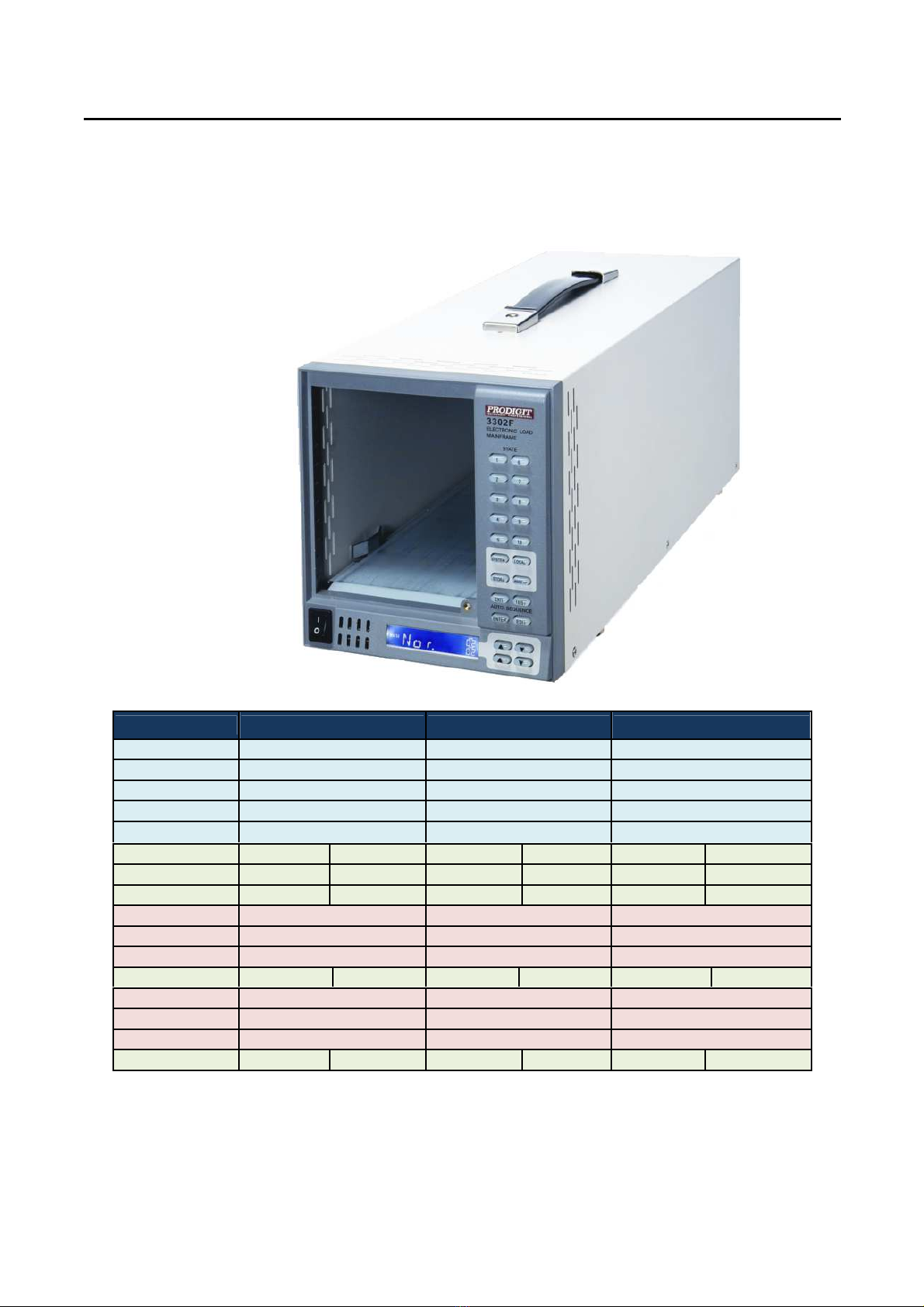
The 3302F electr nic l ad mainframe is required t pr vide the DC p wer c nversi n and
pti nal c mputer c mmunicati ns t the ‘F’ series f L ad M dules. The 3302F is designed
t h use any f the f ll wing m dels:
TABLE 1-1 3310F / 3330F / 3340F/G / 33401F/G SERIES SPECIFICATION LIST
M del Max. current Max. v ltage Max. p wer
3310F 30A 60V 150W
3311F 60A 60V 300W
3312F 12A 250V 300W
3314F 12A 500V 300W
3315F 15A 60V 75W
3330F 60A(CHA)
6A(CHB) 80V(CHA)
80V(CHB)
250W
(CHA)
50W(CHB)
3332F 24A(CHA)
24A(CHB)
80V(CHA)
80V(CHB)
120W(CHA)
120W(CHB)
3336F 3A(CHA) 3A(CHB) 80V(CHA)
80V(CHB)
40W(CHA)
40W(CHB)
3340F 2A 300V 150W
3341F 20A 100V 300W
3342F 2A 500V 300W
33401F 2.4A(CHA)
2.4A(CHB)
500V(CHA)
500V(CHB)
120W(CHA)
120W(CHB)
3341G 24A 300V 300W
3342G 12A 500V 300W
3343G 24A 500V 300W
33401G 6A(CHA) 6A(CHB) 500V(CHA)
500V(CHB)
150W(CHA)
150W(CHB)

2 PRODIGIT
1.1 Features
The 3302F has the f ll wing key features:
1.1.1. Flexible C nfigurati n: The 3302F can be used t h use a variety f ‘F’
Series l ad m dules with different v ltage and current sink ranges.
1.1.2. Plug in Design: It is quick and easy t take a l ad m dule ut f the
Mainframe and t replace it with an ther l ad m dule.
1.1.3. C mputer Interfaces: GPIB,RS232, USB r LAN are pti nally
Available f r rem te c ntr l. The mechanical design f the interface cards.
1.1.4. Fr nt panel mem ry: C mm n test settings can be st red and recalled.
1.1.5. Aut Sequence: Mem ry l cati ns can be linked t f rm a sequence
Against time.
1.1.6. Wake Up Functi n: The mainframe can be set t aut matically revert t a
L ad set up n mains p wer n.
1.1.7. Intelligent C ling: Temperature c ntr lled fans are used t minimise
1.2 Standard Accessories
The following accessories are provi e as stan ar :
1.2.1. M del 3302F
1.2.2. BNC-BNC cable 1m
1.2.3. M del 3302F Operati n Manual 1PC
1.2.4. 3Pin P wer cable 1PC
1.3 Option
1.3.1. GPIB+RS232 interface
1.3.2. RS232 interface
1.3.3. GPIB interface
1.3.4. USB interface + USB DRIVER CD
1.3.5. LAN interface + LAN DRIVER CD
1.3.6. 9933 Rem te C ntr ller 1 PC
1.3.7. GPIB cable 1 M
1.3.8. GPIB cable 2 M
1.3.9. USB TYPE A TO TYPE B cable 1.8 M
1.4 Specifications
The specificati n f 3302F mainframe is sh wn bel w in Table 1-2.
TABLE 1-2 SPECIFICATIONS
LINE 100V/115V±10%
200V/230V±10%
FREQUENCY 50/60 HZ
FUSE T1A/250V
(5*20mm)
T0.5A/250V
(5*20mm)
AC INPUT
MAX. POWER
CONSUMPTION 40 W
DIMENSIONS (W*H*D) 150 mm*177 mm*445 mm
WEIGHT NET : 5.5 Kg

3302F Mainframe Operation Manual 3
C apter 2 Installation
2.1 Inspection
The 3302F mainframe was carefully inspected, tested and calibrated bef re shipment. If
damage t the instrument has ccurred during transp rt, please inf rm Pr digit's sales and
service ffice r representative. Y ur 3302F mainframe was shipped with a p wer c rd f r the
type f utlet used at y ur l cati n. If the appr priated c rd was n t included, please c ntact
y ur nearest sales ffice t btain the c rrect c rd. Refer t "check line v ltage" t check the
line v ltage selecti n and fuse type.
2.2 Check line voltage
The 3302F mainframe can be perated fr m a 100/115 r 200/230Vac input as indicated n
the label n the rear panel. The input is switchable s please make sure that the switch is set
c rrectly f r y ur n minal mains input bef re turning n the mains p wer. The pr cedure
bel w details h w t change the switch p siti n:
2.2.1 With the 3302F mainframe p wer OFF, disc nnect the p wer c rd.
2.2.2 Refer the drawing n the rear panel in Fig 2-1, set the switches t the
Pr per v ltage as described in the f ll wing:
a. Set Switch t 100V/115V f r 115Vac line v ltage
b. Set Switch t 200V/230V f r 230Vac
N te: 100Vac and 200Vac is used f r Japan nly (Opti n)
Fig 2-1 SET OF SWITCH
4 PRODIGIT
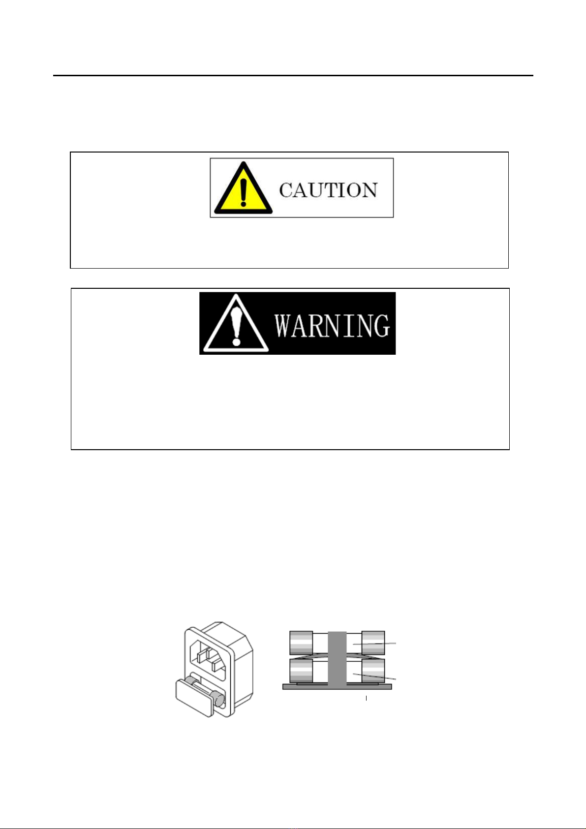
2.3 Input Fuse
This pr duct is fitted with a mains input fuse. If it needs t be replaced please adhere t the
F ll wing pr cedure.
2.3.1 Check the rating f the mains input fuse. Replace nly with the c rrect
Type and rating.
F r 100V/115Vac Input use T1A/250V (5*20mm),
F r 200V/230Vac Input useT0.5A/250V (5*20mm)
2.3.2 The AC line fuse is l cated bel w the AC line s cket (see Fig 2-2). Use
A small screwdriver t rem ve the fuse h lder. Replace the failed fuse
With the appr priate type and rating acc rding t y ur mains v ltage.
(See Table 1-2)
2.3.3 Refit the fuse h lder and c nnect the p wer c rd.
Fig 2-2 FUSE RECEPTACLE
BEFORE replacing the fuse y u must switch ff the unit and mains p wer utlet and
disc nnect the plug f the AC P wer cable fr m the input s cket f the 3302F.
If pri r t exchanging the fuse, there is any abn rmal n ise r d ur d n t use the unit.
Please inf rm y ur l cal sales ffice t rganise repair f the 3302F.
T av id the risk f fire r electr nic sh ck the fuse must nly be replaced with same type
and rating as the riginal. Any replacement fuse used sh uld meet y ur nati nal safety
standards. Any use f impr per fuse r sh rting the Fuse h lder w uld be extremely
danger us and w uld be strictly pr hibited.
T1A/250V (5*20mm)
T0.5A/250V (5*20mm)

3302F Mainframe Operation Manual 5
2.4 Grounding re uirements
SHOCK HAZAR
The unit is gr unded via the AC Input. It must be ensured that the c rrect mains lead with earth
pin is used. C rrect gr unding f y ur electrical system infrastructure acc rding t nati nal
standards must als be bserved.
2.5 Environmental Re uirements
• Ind r use.
• Insulati n Categ ry I.
• P lluti n Degree 2.
• Altitude up t 2000 meters
• Relative Humidity 80% Max (n n-c ndensing).
• Ambient Temperature 0 t 40°C
• The ideal perating temperature is 25°C ± 5°C
2.6 Observe the International Electrical Symbol Listed Below
Warning!Risk f electric sh ck.
Cauti n!Refer t this manual bef re using the instrument.
2.7 Cleaning
To clean this pro uct uses a soft or slightly amp cloth.
BEFORE y u clean the unit, switch the mains p wer ff and disc nnect the input lead.
・ Please d NOT use any rganic s lvent capable f changing the nature f the plastic
such as benzene r acet ne.
・ Please ensure that n liquid is all wed t penetrate this pr duct.
6 PRODIGIT
2.8 Power Up
The f ll wing pr cedure sh uld be f ll wed bef re applying mains p wer:
The f ll wing pr cedure sh uld be f ll wed bef re applying mains p wer:
• Check that the POWER switch is in the ff (O) p siti n
• Check the rear panel v ltage select r f the 3302F is c rrectly set.
• Check that n thing is c nnected t the DC INPUT (l ad input terminals) n
The fr nt and rear panels.
• C nnect c rrect AC mains lead t the 3302F
• Turn n (I) the POWER switch.
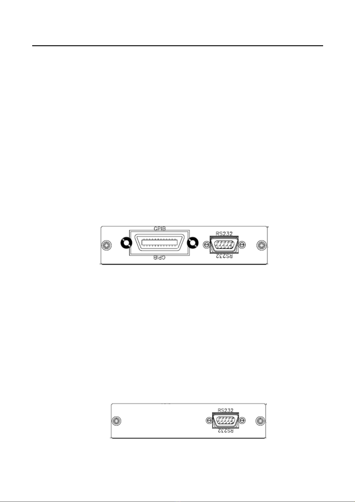
2.9 GPIB & RS232 connection option
If y ur 3302F is fitted with GPIB + RS232 interface card then the rear panel will have the
necessary interface s ckets as sh wn in Fig 2-3. This c nnects the 3302F mainframe t
RS232 r GPIB p rt f y ur c mputer.
GPIB and RS232 interface can nly be used at the same time, t Change the interface must
reb t unit.
Fig 2-3 3302F REAR PANEL
The RS232 BAUD-RATE can be set in the fr nt panel f the 3302F. Press the “SYSTEM”
butt n twice t enter the BAUD RATE adjustment.
A GPIB system can be c nnected in any c nfigurati n (star, linear, r b th) as l ng as
• The maximum number f devices including the c ntr ller is n m re than 15.
• The maximum length f the GPIB cable is n m re than 2 meters.
• The t tal lead length f all devices c nnected t gether t tal <20 meters
2.10 RS232 Interface Option
Fig 2-4 sh ws the RS232 c nnect r (Female) n the rear panel. This c nnects the 3302F
mainframe t RS232 p rt f c mputer. The RS232 BAUD-RATE can be set in the fr nt panel
f the 3302F. Press the “SYSTEM” butt n twice t enter the BAUD RATE adjustment.
Fig 2-4 3302F RS232 C nnecti n

3302F Mainframe Operation Manual 7
2.11 GPIB connection option
The GPIB c nnect r is l cated n the rear panel. This s cket all ws the 3302F t be
c nnected t the c ntr ller and ther GPIB devices. A GPIB system can be c nnected in any
c nfigurati n (star, linear, r b th) as l ng as
• The maximum number f devices including the c ntr ller is ≤15.
• The maximum length f the GPIB cable is n m re than 2 meters times.
• The t tal lead length f all devices c nnected t gether t tal <20 meters.
• Please make sure the l ck screws are firmly hand-tightened, use a
Screwdriver nly f r the rem val f screws. Fig 2-5 sh ws the rear
Panel f 3302F mainframe, The GPIB address f the 3302F mainframe is
Set n fr nt panel.
Fig 2-5 3302F REAR PANEL
2.12 USB Connection Option
Fig 2-6 sh ws the USB c nnect r in the rear panel f 3302F mainframe. Please refer
Appendix B.
Fig 2-6 3302F USB C nnecti n
2.13 LAN Connection Option
Fig 2-7 sh ws the LAN c nnect r in the rear panel f 3302F mainframe. Please refer
Appendix C.
Fig 2-7 3302F LAN C nnecti n

8 PRODIGIT
2.14 Remote Controller Option
A wired rem te c ntr ller (P/N : 9933) can be c nnected t the mainframe.
Fig 2-8 sh ws the rem te c ntr ller s cket which is l cated n the rear panel.
Fig 2-8 3302F Rem te c ntr ller C nnecti n
2.15 Remote Controller Connection
Fig 2-9 sh ws pin assignments f r the DSUB-15 c nnect r when the rem te c ntr ller pti n
is fitted t the 3302F mainframe. The rem te c ntr ller all ws the first 10 mem ry l cati ns t
be recalled. Set ups saved at these mem ry l cati ns can include dynamic wavef rms and
the l ad ON state.
N te 1: O/P as a set f NG TTL High level signal utput.
N te 2: The L ad butt n n the rem te c ntr ller d es n t perate f r
The 3302F/3305F mainframes, H wever the L ad ON state can be saved as part f
The set up st red in ne f the mem ry l cati ns.
Fig 2-9 M del 9933 Rem te c ntr ller C nnecti n
3302F Mainframe Operation Manual 9
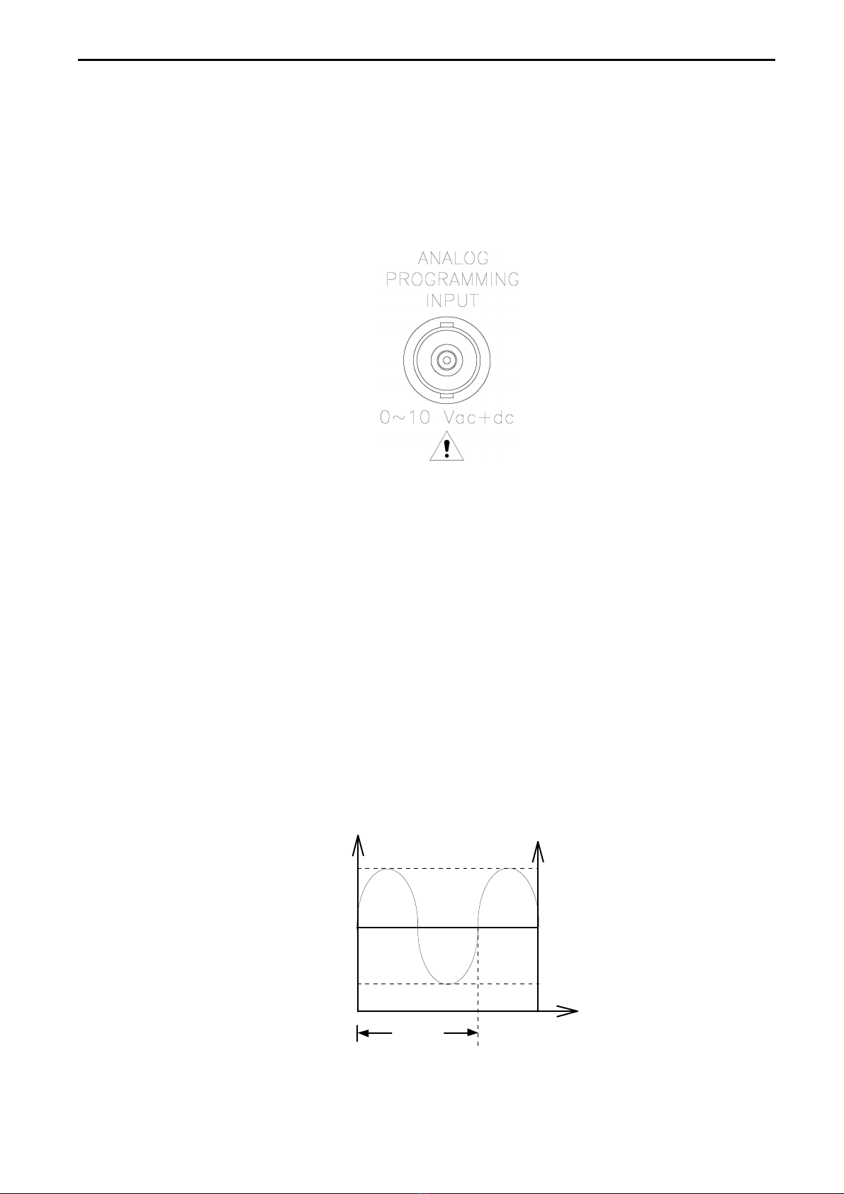
2.16 Analog Programming Input
The 3302F mainframe has an analogue programming input. This feature allows an external
waveform to be tracked as long as it is within the load’s dynamic capabilities. The analogue
programming input is configured as a NC socket. It will accept a 0-10V signal. This signal
is proportional to the load module’s maximum current range. Please note that the analogue
programming input will only operate with single channel load modules. It cannot be used for
dual channel load modules from the 3330F series and 33401F/G.
Fig 2-10 Diagram of analog programming input
The analogue programming input operates in CC or CP modes only. The Load Module
will attempt to load proportionally according to the signal and the load module’s maximum
current or power range.
For example: 3311F: Imax = 60A and Pmax = 300W
So in CC mode if analogue programming input is 5V = 30A load setting
Or in CP mode if analogue programming input is 1V = 30W load setting
The analog programming signal can act alone or it can be summed with the programmed
value set via the front panel or the optional computer interface (GPI , RS232, US , or
LAN) or the front panel.
Example:
Fig 2-11 shows the result of an analog programming signal at 4Vac, 500Hz when it is
summed with a 24A programmed setting in CC mode of 3311F Load module.
Fig 2-11 Analog Programming Example
2mS
T
LOAD CURRENT
6V
4V
2V
12A
24A
36A
ANALOG V
10 PRODIGIT
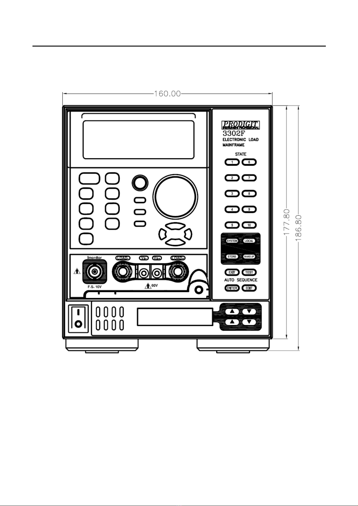
Chapter 3 Mainframe Operation
The front panel of 3302F mainframe is shown in Fig 3-1.
Fig 3-1 3302F FRONT PANEL
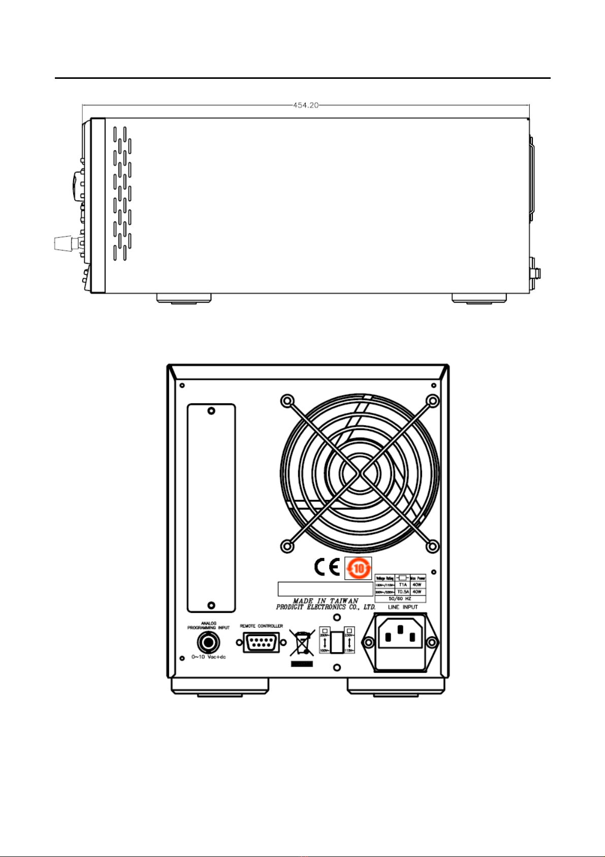
3302F Mainframe Operation Manual 11
Fig 3-2 3302F IDE PANEL
Fig 3-3 3302F REAR PANEL
This manual suits for next models
20
Table of contents
Popular Industrial Electrical manuals by other brands

Murata
Murata GRM188R61E684MA75 Series Reference sheet

Murata
Murata GQM2195C2E470GB12 Series Reference sheet

Fluke
Fluke HYDRA III Series Remote Programmers Guide

Siemens
Siemens 7XR61 Series Short directions for use

Murata
Murata GRM319R71C105KAA3 Series Reference sheet

Vimar
Vimar by-me 01470.1 quick start guide

Murata
Murata GJM0335C1HR50WB01 Series Reference sheet

Lucent Technologies
Lucent Technologies Lineage 2000 J85502C-1 product manual

Murata
Murata GJM1555C1H3R3DB01 Series Reference sheet

Cervis
Cervis SmaRT DIN-9H4R-2DI user manual

Eaton
Eaton SPDT3 Series Instruction leaflet

Vimar
Vimar By-alarm 01717 quick start guide


