Lütze CPS2B1-480-24 User manual

DE Manual d'instructionsInstruction ManualBeipackzettel EN FR
Friedrich Lütze GmbH ■ Bruckwiesenstr. 17–19 ■ D-71384 Weinstadt ■ GERMANY www.luetze..de www.luetze.com www.luetze.fr
DE EN FR
919846.0000, L72-193-8847L_00 30.08.2019 Copyright by Lütze (Weinstadt), Printed in Germany
1/4
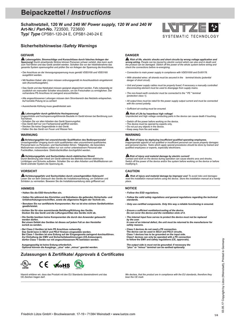
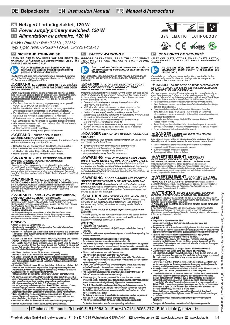
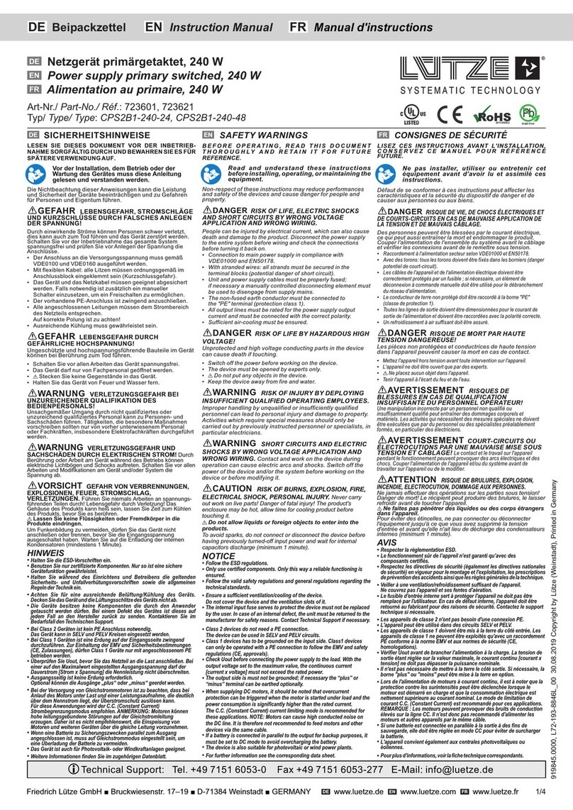
SICHERHEITSHINWEISE
LESEN SIE DIESES DOKUMENT VOR DER INBETRIEB-
NAHME SORGFÄLTIG DURCH UND BEWAHREN SIE ES FÜR
SPÄTERE VERWENDUNG AUF.
Vor der Installation, dem Betrieb oder der
Wartung des Gerätes muss diese Anleitung
gelesen und verstanden werden.
Die Nichtbeachtung dieser Anweisungen kann die Leistung
und Sicherheit der Geräte beeinträchtigen und zu Gefahren
für Personen und Eigentum führen.
GEFAHR LEBENSGEFAHR, STROMSCHLÄGE
UND KURZSCHLÜSSE DURCH FALSCHES ANLEGEN
DER SPANNUNG!
Durch einwirkende Ströme können Personen schwer verletzt,
dies kann auch zum Tod führen und das Gerät zerstört werden.
Schalten Sie vor der Inbetriebnahme das gesamte System
spannungsfrei und prüfen Sie vor Anlegen der Spannung die
Anschlüsse.
▪ Der Anschluss an die Versorgungsspannung muss gemäß
VDE0100 und VDE0160 ausgeführt werden.
▪ Mit flexiblen Kabel: alle Litzen müssen ordnungsgemäß im
Anschlussblock eingeklemmt sein (Kurzschlussgefahr).
▪ Das Gerät und das Netzkabel müssen geeignet abgesichert
werden. Falls notwendig ist zusätzlich ein manueller
Schalter einzusetzen, um ein Freischalten zu ermöglichen.
▪ Der vorhandene PE-Anschluss ist zwingend anzuschließen.
▪ Alle angeschlossenen Leitungen müssen dem Strombereich
des Netzteils entsprechen.
Auf korrekte Polung ist zu achten!
▪ Ausreichende Kühlung muss gewährleistet sein.
GEFAHR LEBENSGEFAHR DURCH
GEFÄHRLICHE HOCHSPANNUNG!
Ungeschützte und hochspannungsführende Bauteile im Gerät
können bei Berührung zum Tod führen.
▪ Schalten Sie vor allen Arbeiten das Gerät spannungsfrei.
▪ Das Gerät darf nur von Fachpersonal geöffnet werden.
▪ Stecken Sie keine Gegenstände in das Gerät.
▪ Halten Sie das Gerät von Feuer und Wasser fern.
WARNUNG VERLETZUNGSGEFAHR BEI
UNZUREICHENDER QUALIFIKATION DES
BEDIENPERSONALS!
Unsachgemäßer Umgang durch nicht qualifiziertes oder
unzureichend qualifiziertes Personal kann zu Personen- und
Sachschäden führen. Tätigkeiten, die besondere Maßnahmen
vorschreiben sollten nur von vorher unterwiesenem Personal
oder Fachkräften, insbesondere Elektrofachkräften durchgeführt
werden.
WARNUNG VERLETZUNGSGEFAHR UND
SACHSCHÄDEN DURCH ELEKTRISCHEN STROM! Durch
Berührung oder Arbeit am Gerät während des Betriebs können
elektrische Lichtbögen und Schocks auftreten. Schalten Sie vor allen
Arbeiten und Modifikationen am Gerät und/oder System die
Spannung ab.
VORSICHT GEFAHR VON VERBRENNUNGEN,
EXPLOSIONEN, FEUER, STROMSCHLAG,
VERLETZUNGEN. Führen Sie niemals Arbeiten an spannungs-
führenden Teilen durch! Lebensgefahr durch Verletzung! Das
Gehäuse des Produkts kann heiß sein, lassen Sie Zeit zum Kühlen
des Produkts, bevor Sie es berühren.
Lassen Sie keine Flüssigkeiten oder Fremdkörper in die
Produkte eindringen.
Um Funkenbildung zu vermeiden, dürfen Sie das Gerät nicht
anschließen oder trennen, bevor Sie die Eingangsspannung
ausgeschaltet haben. Warten Sie auf die Entladung der internen
Kondensatoren (mindestens 1 Minute).
HINWEIS
§Halten Sie die ESD-Vorschriften ein.
§Benutzen Sie nur zertifizierte Komponenten. Nur so ist eine sichere
Gerätefunktion gewährleistet.
§Halten Sie während des Einrichtens und Betreibens die geltenden
Sicherheits- und Unfallverhütungsvorschriften sowie die allgemeinen
Regeln der Technik ein.
§Achten Sie für eine ausreichende Belüftung/Kühlung des Geräts.
Decken Sie das Gerät und die Lüftungsschlitze des Geräts nicht ab.
§Die Geräte besitzen keine Komponenten die durch den Anwender
getauscht werden dürfen. Bei einem Defekt des Gerätes ist dieses auf
jedem Fall an den Hersteller zurück zu senden. Kontaktieren Sie im
Bedarfsfall den Technischen Support.
§Bei Class 2 Geräten ist kein PE Anschluss notwendig.
Das Gerät kann in SELV und PELV Kreisen eingesetzt werden.
§Bei Class 1 Geräten ist eine Erdung auf der Eingangsseite zwingend
durchzuführen. Zur Einhaltung der EMV und Sicherheitsbestimmungen
(CE, Zulassungen), dürfen Class 1 Geräte nur mit angeschlossenem PE
betrieben werden.
§Überprüfen Sie Uout, bevor Sie das Netzteil an die Last anschließen. Bei
einer auf den Maximalwert eingestellten Ausgangsspannung darf der
Dauerstrom [Strom x Spannung] die Nennleistung nicht überschreiten.
§Ausgangsseitig ist keine Erdung erforderlich.
Optional können die Ausgänge „plus“ oder „minus“ geerdet werden.
§Bei der Versorgung von Gleichstrommotoren ist zu beachten, dass bei
Anlauf des Motors unter Last und einer Leistungsaufnahme, die deutlich
über dem Nennstrom liegt, der Überstromschutz auslösen kann.
Für diese Anwendungen wird der C.C. (Constant Current)
Strombegrenzungsmodus empfohlen. ANMERKUNG: Motoren können
hohe leitungsgebundene Störungen auf der Gleichstromleitung
erzeugen. Daher ist es nicht empfehlenswert, die Einspeisung von
Motoren und weiteren Geräten über die gleiche Leitung vorzunehmen.
§Wenn eine Batterie zu Sicherungszwecken parallel zum Ausgang
angeschlossen ist, muss auf Gleichstrommodus eingestellt sein, um
eine Überladung der Batterie zu vermeiden.
§Das Gerät ist auch für Photovoltaik- oder Windkraftanlagen geeignet.
§Weitere Informationen finden Sie im zugehörigen Datenblatt.
DE
SAFETY WARNINGS
B E F O R E O P E R AT I N G , R E A D T H I S D O C U M E N T
T H O R O U G H L Y A N D R E T A I N I T F O R F U T U R E
REFERENCE.
Read and understand these instructions
before installing, operating, or maintaining the
equipment.
Non-respect of these instructions may reduce performances
and safety of the devices and cause danger for people and
property.
DANGER RISK OF LIFE, ELECTRIC SHOCKS
AND SHORT CIRCUITS BY WRONG VOLTAGE
APPLICATION AND WRONG WIRING.
People can be injured by electrical current, which can also cause
death and damage to the product. Disconnect the power supply
to the entire system before wiring and check the connections
before turning it back on.
▪ Connection to main power supply in compliance with
VDE01000 and .EN50178
▪ With stranded wires: all strands must be secured in the
terminal blocks (potential danger of short circuit).
▪ Unit and power supply cables must be properly fused;
if necessary a manually controlled disconnecting element must
be used to disengage from supply mains.
▪ The non-fused earth conductor must be connected to
the "PE" terminal (protection class 1).
▪ All output lines must be rated for the power supply output
current and must be connected with the correct polarity.
▪ Sufficient air-cooling must be ensured.
DANGER RISK OF LIFE BY HAZARDOUS HIGH
VOLTAGE!
Unprotected and high voltage conducting parts in the device
can cause death if touching.
▪ Switch off the power before working on the device.
▪ The device must be opened by experts only.
▪ Do not put any objects in the device.
▪ Keep the device away from fire and water.
WARNING RISK OF INJURY BY DEPLOYING
INSUFFICIENT QUALIFIED OPERATING EMPLOYEES.
Improper handling by unqualified or insufficiently qualified
personnel can lead to personal injury and damage to property.
Activities which require special measures should only be
carried out by previously instructed personnel or specialists, in
particular electricians.
WARNING SHORT CIRCUITS AND ELECTRIC
SHOCKS BY WRONG VOLTAGE APPLICATION AND
WRONG WIRING. Contact and work on the device during
operation can cause electric arcs and shocks. Switch off the
power of the device and/or the system before working on the
device or before modifying it.
CAUTION RISK OF BURNS, EXPLOSION, FIRE,
ELECTRICAL SHOCK, PERSONAL INJURY. Never carry
out work on live parts! Danger of fatal injury! The product's
enclosure may be hot, allow time for cooling product before
touching it.
Do not allow liquids or foreign objects to enter into the
products.
To avoid sparks, do not connect or disconnect the device before
having previously turned-off input power and wait for internal
capacitors discharge (minimum 1 minute).
NOTICE
§Follow the ESD regulations.
§Only use certified components. Only this way a reliable functioning is
ensured.
§Follow the valid safety regulations and general regulations regarding the
technical standards.
§Ensure a sufficient ventilation/cooling of the device.
Do not cover the device and the ventilation slots of it.
§The internal input fuse serves to protect the device must not be replaced
by the user. In case of an internal defect, the unit must be returned to the
manufacturer for safety reasons. Contact Technical Support if necessary.
§Class 2 devices do not need a PE connection.
The device can be used in SELV and PELV circuits.
§Class 1 devices has to be grounded on the input side. Class1 devices
can only be operated with a PE connection to follow the EMV and safety
regulations (CE, approvals).
§Check Uout before connecting the power supply to the load. With the
output voltage set to the maximum value, the continuous current
[current x voltage] must not exceed the rated power.
§The output side is must not be grounded; if necessary the “plus” or
“minus” terminal can be earthed optionally.
§When supplying DC motors, it should be noted that overcurrent
protection can be triggered when the motor is started under load and the
power consumption is significantly higher than the rated current.
The C.C. (Constant Current) current limiting mode is recommended for
these applications. NOTE: Motors can cause high conducted noise on
the DC line. It is therefore not recommended to feed motors and other
devices via the same cable.
§If a battery is connected in parallel to the output for backup purposes, it
must be set to DC mode to avoid overcharging the battery.
§The device is also suitable for photovoltaic or wind power plants.
§For further information see the corresponding data sheet.
EN
CONSIGNES DE SÉCURITÉ
LISEZ CES INSTRUCTIONS AVANT L'INSTALLATION,
C O N S E R V E Z C E M A N U E L P O U R R É F É R E N C E
FUTURE.
Ne pas installer, utiliser ou entretenir cet
équipement avant d’avoir lu et assimilé ces
instructions.
Défaut de se conformer à ces instructions peut affecter les
caractéristiques et la sécurité du dispositif de danger et de
causer aux personnes ou aux biens.
DANGER RISQUE DE VIE, DE CHOCS ÉLECTRIQUES ET
DE COURTS-CIRCUITS EN CAS DE MAUVAISE APPLICATION DE
LA TENSION ET DE MAUVAIS CÂBLAGE.
Des personnes peuvent être blessées par le courant électrique,
ce qui peut aussi entraîner la mort et endommager le produit.
Couper l'alimentation de l'ensemble du système avant le câblage
et vérifier les connexions avant de le remettre sous tension.
▪ Raccordement à l'alimentation secteur selon VDE01000 et . EN50178
▪ Avec des torons: tous les torons doivent être fixés dans les borniers (danger
potentiel de court-circuit).
▪ Les câbles de l'appareil et de l'alimentation électrique doivent être
correctement protégés par un fusible ; si nécessaire, un élément de
déconnexion à commande manuelle doit être utilisé pour le débranchement
du réseau d'alimentation.
▪ Le conducteur de terre non protégé doit être raccordé à la borne "PE"
(classe de protection 1).
▪ Toutes les lignes de sortie doivent être dimensionnées pour le courant de
sortie de l'alimentation et doivent être raccordées avec la polarité correcte.
▪ Un refroidissement à air suffisant doit être assuré.
DANGER RISQUE DE MORT PAR HAUTE
TENSION DANGEREUSE!
Les pièces non protégées et conductrices de haute tension
dans l'appareil peuvent causer la mort en cas de contact.
▪ Mettez l'appareil hors tension avant toute intervention sur l'appareil.
▪ L'appareil ne doit être ouvert que par des experts.
▪ Ne placez aucun objet dans l'appareil.
▪ Tenir l'appareil à l'écart du feu et de l'eau.
AVERTISSEMENT RISQUES DE
BLESSURES EN CAS DE QUALIFICATION
INSUFFISANTE DU PERSONNEL OPÉRATEUR!
Une manipulation incorrecte par un personnel non qualifié ou
insuffisamment qualifié peut entraîner des dommages corporels et
matériels. Les activités qui nécessitent des mesures spéciales ne doivent
être exécutées que par du personnel ou des spécialistes préalablement
formés, en particulier des électriciens.
AVERTISSEMENT COURT-CIRCUITS OU
ÉLECTROCUTIONS PAR UNE MAUVAISE MISE SOUS
TENSION ET CÂBLAGE! Le contact et le travail sur l'appareil
pendant le fonctionnement peuvent provoquer des arcs électriques et des
chocs. Couper l'alimentation de l'appareil et/ou du système avant de
travailler sur l'appareil ou de le modifier.
ATTENTION RISQUE DE BRULURES, EXPLOSION,
INCENDIE, ELECTROCUTION, DOMMAGE AUX PERSONNES.
Ne jamais effectuer des opérations sur les parties sous tension!
Danger de mort! Le récipient peut produire des brulures, le laisser
refroidir avant de toucher l'appareil.
Ne faites pas pénétrer des liquides ou des corps étrangers
dans l'appareil.
Pour éviter des étincelles, ne pas connecter ou déconnecter
l'équipement jusqu'à ce que vous avez supprimé la tension
d'entrée et avant qu'elle n'ait lieu de décharge des condensateurs
internes (minimum 1 minute).
AVIS
§Respecter la réglementation ESD.
§Le fonctionnement sûr de l’appreil n’est garanti qu’avec des
composants certifiés.
§Respectez les directives de sécurité (également les directives nationales
de sécurité) en vigueur pour le montage et l'exploitation, les prescriptions
de prévention des accidents ainsi que les règles générales de la technique.
§Veiller à une ventilation/refroidissement suffisant de l'appareil.
Ne couvrez pas l'appareil et ses fentes d'aération.
§Le fusible d'entrée interne sert à protéger l'appareil ne doit pas être
remplacé par l'utilisateur. En cas de défaut interne, l'appareil doit être
retourné au fabricant pour des raisons de sécurité. Contactez le support
technique si nécessaire.
§Les appareils de classe 2 n'ont pas besoin d'une connexion PE.
§L'appareil peut être utilisé dans des circuits SELV et PELV.
§Les appareils de classe 1 doivent être mis à la terre du côté entrée. Les
appareils de classe 1 ne peuvent être exploités qu'avec un raccordement
PE conforme à la norme EMV et aux normes de sécurité (CE,
homologations).
§Vérifier Uout avant de brancher l'alimentation à la charge. La tension de
sortie étant réglée sur la valeur maximale, le courant continu [courant x
tension] ne doit pas dépasser la puissance nominale.
§Il n'est pas nécessaire de mettre à la terre le côté sortie. Si nécessaire, la
borne "plus" ou "moins" peut être mise à la terre en option.
§Lors de l'alimentation de moteurs à courant continu, il est à noter que la
protection contre les surintensités peut être déclenchée lorsque le
moteur est démarré en charge et que la consommation électrique est
nettement supérieure au courant nominal. Le mode de limitation de
courant C.C. (Constant Current) est recommandé pour ces applications.
REMARQUE : Les moteurs peuvent provoquer des bruits de conduction
élevés sur la ligne CC. Il n'est donc pas recommandé d'alimenter les
moteurs et autres appareils par le même câble.
§Si une batterie est connectée en parallèle à la sortie à des fins de
sauvegarde, elle doit être réglée en mode CC pour éviter de surcharger
la batterie.
§L'appareil convient également aux centrales photovoltaïques ou
éoliennes.
§Pour plus d'informations, voir la fiche technique correspondants.
FR
iTechnical Support: Tel. +49 7151 6053-0 Fax +49 7151 6053-277 E-Mail: info@luetze.de
Schaltnetzteil, 480 W
Power supply, 480 W
Alimentation, 480 W
Art-Nr./ Part-No./ Réf.: 723700, 723721
Typ/ Type/ Type: CPS2B1-480-24, CPS2B1-480-48
DE
EN
FR

DE Manual d'instructionsInstruction ManualBeipackzettel EN FR
Technische Änderungen vorbehalten. Zum späteren Gebrauch aufbewahren! Technical changes reserved. Store for later use! Sous réserve de modifications techniques. Conserver pour uneutilisation ultérieure!
DE EN FR
Friedrich Lütze GmbH ■ Bruckwiesenstr. 17–19 ■ D-71384 Weinstadt ■ GERMANY www.luetze..de www.luetze.com www.luetze.fr
DE EN FR
2/4
The permissible ambient conditions must be
observed. (See data sheet.)
Die zulässigen Umgebungsbedingungen müssen
eingehalten werden. (Siehe Datenblatt.) Les conditions ambiantes admissibles doivent être
respectées. (Voir fiche technique.)
Bestimmungsgemäßer Gebrauch
DE
Intended use
EN
Utilisation conforme
FR
Wenn das Gerät in einer vom Hersteller nicht
bestimmungsgemäßen Weise verwendet wird, kann der
durch das Gerät gebotene Schutz beeinträchtigt werden.
If the equipment is used in a manner not specified by the
manufacturer, the protection provided by the equipment
may be impaired.
Si l'équipement est utilisé d'une manière non spécifiée
par le fabricant, la protection fournie par l'équipement
peut être compromise.
The total power (UA x IA) must not exceed the
nominal power of the unit.
Die Gesamtleistung (UA x IA) darf nicht die
Nennleistung des Gerätes überschreiten.
La puissance totale (UA x IA) ne doit pas dépasser la
puissance nominale de l'appareil.
22...29V / 45...55V
723700 / 723721
22...29V / 45...55V
723700 / 723721
22...29V / 45...55V
723700 / 723721
10117
140
139
56
CPS2B1-480-48
723721
48VDC/10A
45...55V
X1:
X2:
X3:
56
CPS2B1-480-24
723700
24VDC/20A
22...29V
X1:
X2:
X3:
723700
CPS2B1-480-24
3
2
1
47
5 6
8 8
723721
CPS2B1-480-48
12
Abbildung ähnlich
Picture similar
Image similaire
DE
EN
FR
723700, 723721
Anzeige Farbe Typ Beschreibung
Display Color Type Discription
Affichage Couleur Type Discription
LED 1 grün DC OK grün an Alle Funktionen und IN/OUT Parameter sind in Ordnung
green green on All functions and IN/OUT parameters are OK
vert allumée en vert Toutes les fonctions et paramètres IN/OUT sont OK
grün aus Kurzschluss am Ausgang, keine Betriebsspannung, interner Fehler
green off Short Circuit on the output, not power supply, internal error
verte éteinte Court-circuit sur la sortie, pas d'alimentation, erreur interne
LED 2 rot Overload rot an Iout > 1,1 IN, Überlast, Kurzschluss
red red on Iout > 1,1 IN, overload, short circuit
rouge allumée en rouge Iout > 1,1 IN, surcharge, court-circuit
Beschreibung
1 X1: AC/DC Eingang
2 X3: Diagnose Ausgang - (3,4)
(Relaiskontakt Schließer, potentialfreier
Kontakt, NC-Ausgang OK)
3 X2: DC Ausgang (Last) - (1,2)
4 Auswahl Überlastverhalten
(Hiccup/C.C. Mode)
5 Grüne LED: Ausgang OK
6 Rote LED: Überlast
7 Abgleich Ausgangsspannung
8 Hutschienenaufrastung
DE Discription
1 X1: AC/DC Input
2 X3: Diagnostic output - (3,4)
(Relay contact N/O contact,
dry contact, NC output OK)
3 X2: DC output (load) - (1,2)
4 Selectable limitation mode
(Hiccup/C.C. Mode)
5 Green LED: Output OK
6 Red LED: Overload
7 Output voltage adjustment
8 DIN rail mounting
EN Discription
1 X1: Entrée AC/DC
2 X3: Sortie de diagnostic - (3,4)
(Contacts de relais Contacts à fermeture,
contact sec, sortie NF OK)
3 X2: Sortie DC (charge) - (1,2)
4 Mode de limitation sélectionnable
(Hiccup/C.C. Mode)
5 LED vert: Sortie OK
6 LED rouge: Surcharge
7 Réglage de la tension de sortie
8 Montage sur rail DIN
FR
LED Statut
FR
LED Status
EN
LED Status
DE
Potentiometer
DE
7
Potentiometer
EN
7
Potentiomètre
FR
7
Das Potentiometer dient zur Einstellung der
Ausgangsspannung (Uout). The potentiometer is used to adjust the output voltage
(Uout).
Le potentiomètre sert à régler la tension de sortie
(Uout).
Produktaufbau Product Assembly Structure du produit
DE EN FR
Ausgangsschutz: Das Gerät ist gegen Überlast (OL) /
Kurzschluss (SC) / Überspannung (OV) / Übertemperatur
(OT) geschützt: Der HICCUP-Modus oder der C.C. Modus
sind mit Jumper wählbar.
OL-Verhalten im HICCUP Modus: Max. OL = 1,5 x In
bleibt die Ausgangsspannung bei Nennspannung für 5s
konstant und das Gerät startet dann einen EIN/AUS-Zyklus.
OL-Verhalten im C.C.-Modus: Der maximale Ausgangsstrom
ist auf 1,1 x In begrenzt, wenn der Lastwiderstand weiter
verringert wird, beginnt die Ausgangsspannung zu fallen.
SC-Verhalten im HICCUP Modus: Das Gerät liefert 1,5 x In für
5s, danach schaltet es sich für 10s aus. Der EIN/AUS-Zyklus
wird kontinuierlich wiederholt.
SC-Verhalten im C.C.-Modus: Das Gerät liefert 1,1 x In
kontinuierlich in den Kurzschluss, ohne abzuschalten.
OV-Schutz des Ausgangsstromkreises: Der Ausgang ist
gegen potenzielle OV aufgrund einer internen Fehlfunktion oder
von der Last für Uout ≥ Unom x 1,2 - 1,3, je nach Modell,
geschützt. (Vgl. Kapitel: Technische Daten.)
OT-Schutz: schaltet das Gerät aus, wenn die Innentemperatur
einen sicheren Grenzwert überschreitet.
HINWEIS Das Gerät startet nach dem Abkühlen automatisch
neu. Um den Normalbetrieb wiederherzustellen, reduzieren Sie
die Lufttemperatur um das Netzteil herum, erhöhen Sie die
Kühlung oder reduzieren Sie die Last.
Output protection: The device is protected against
overload (OL) / short circuit (SC) / overvoltage (OV) /
overtemperature (OT): The HICCUP mode or C.C. mode are
selectable with Jumper .
OL behaviour in HICCUP mode: Max. OL = 1.5 x In
the output voltage remains constant at rated voltage for 5s and
then the device starts an ON/OFF cycle.
OL behaviour in C.C. mode: The maximum output current is
limited at 1.1 x In if the load resistance is further decreased the
output voltage starts to drop.
SC behaviour in HICCUP mode: The device delivers 1.5 x In
for 5s, then switches off for 10s. The ON/OFF cycle is repeated
continuously.
SC behavior in C.C. mode: The device supplies 1.1 x In
continuously into the short circuit without switching off.
Output OV circuit protection: The output is protected against
potential OV due to an internal malfunction or from the load for
Uout ≥ Unom x 1.2 - 1.3, depending on the model.
(See chapter: Technical data.)
OT protection: Turns the unit off when the internal temperature
exceeds a safe limit.
NOTICE The unit restarts automatically after cooling down. To
restore normal operation, reduce the air temperature around the
power supply, increase cooling or reduce load.
Protection de sortie : L'appareil est protégé contre les
surcharges (OL) / courts-circuits (SC) / surtensions (OV) /
surchauffes (OT): Le mode HICCUP ou le mode C.C.
peuvent être sélectionnés avec le cavalier .
Comportement OL en mode HICCUP: Max. OL = 1,5 x In
la tension de sortie reste constante à la tension nominale
pendant 5 s et l'appareil démarre alors un cycle ON/OFF.
Comportement OL en mode C.C.: Le courant de sortie
maximum est limité à 1,1 x In si la résistance de charge est
encore diminuée, la tension de sortie commence à baisser.
Comportement SC en mode HICCUP: L'appareil délivre 1,5 x
In pendant 5s, puis s'éteint pendant 10s. Le cycle ON/OFF est
répété en continu.
Comportement SC en mode C.C.: L'appareil alimente 1,1 x In
en continu dans le court-circuit sans coupure.
Protection du circuit OV de sortie: La sortie est protégée
contre le potentiel OV dû à un dysfonctionnement interne ou à
la charge pour Uout ≥ Unom x 1.2 - 1.3, selon le modèle.
(Voir chapitre : Caractéristiques techniques.)
Protection OT: éteint l'appareil lorsque la température
intérieure dépasse une limite de sécurité.
AVIS L'appareil redémarre automatiquement après
refroidissement. Pour rétablir le fonctionnement normal, réduire
la température de l'air autour de l'alimentation électrique,
augmenter le refroidissement ou réduire la charge.
4
44

DE Manual d'instructionsInstruction ManualBeipackzettel EN FR
Technische Änderungen vorbehalten. Zum späteren Gebrauch aufbewahren! Technical changes reserved. Store for later use! Sous réserve de modifications techniques. Conserver pour uneutilisation ultérieure!
DE EN FR
Friedrich Lütze GmbH ■ Bruckwiesenstr. 17–19 ■ D-71384 Weinstadt ■ GERMANY www.luetze..de www.luetze.com www.luetze.fr
DE EN FR
3/4
Installation
DE
Installation
EN
Installation
FR
Pinbelegung Pin Assignment Affectation des broches
DE EN FR
Montage
▪ Montage auf DIN –Tragschiene nach
IEC 60715 TH35-7.5(-15).
▪ Einbaulage: vertikal
1. Kippen Sie das Gerät leicht nach hinten.
2. Hängen Sie das Gerät über
die Oberkante der Schiene.
3. Schieben Sie es nach unten, bis es auf
den Anschlag trifft.
4. Drücken Sie zum Verriegeln gegen die
Unterseite. Bis Sie ein Klicken hören.
DE
Montage
▪ Montage sur rail DIN selon
IEC 60715 TH35-7.5(-15).
▪ Position de montage: verticale
1. Inclinez légèrement l'appareil vers l'arrière.
2. Installez l'appareil sur le bord supérieur du rail.
3. Faites-le glisser vers le bas jusqu'à ce qu'il
atteigne la butée.
4. Appuyez contre le fond pour verrouiller.
Jusqu'à ce que vous entendiez un déclic.
FR
Mounting
▪ Mounting on DIN hat rail according
IEC 60715 TH35-7.5(-15).
▪ Installation position: vertical
1. Tilt the unit slightly backwards.
2. Fit the unit over the top edge of the rail.
3. Slide it downward until it hits the stop.
4. Press against the bottom to lock.
Until you hear a click.
EN
Empfohlene Verdrahtung
DE Câblage recommandé
FR
Recommended Wiring
EN
Eingangsanschlüsse Input connections Connexions d'entrée
DE EN FR
HINWEIS Um der UL-Zertifizierung zu entsprechen, verwenden
Sie geeignete Kupferkabel, die der erforderlichen Spannung und
dem erforderlichen Strom entsprechen, mit einem spezifizierten
Querschnitt, der für die jeweilige Betriebstemperatur ausgelegt ist:
60°C für Umgebungen bis 45°C, 75°C für Umgebungen bis 60°C
und 90°C für Umgebungen bis 70°C.
NOTICE To comply with UL certification, use suitable copper
cables that match the required voltage and current, with a specified
cross section designed for the appropriate operating temperature:
60°C for environments up to 45°C, 75°C for environments up to
60°C, and 90°C for environments up to 70°C.
AVIS Pour se conformer à la certification UL, utilisez des câbles
en cuivre appropriés qui correspondent à la tension et au courant
requis, avec une section transversale spécifiée conçue pour la
température de fonctionnement appropriée : 60°C pour des
environnements jusqu'à 45°C, 75°C pour des environnements
jusqu'à 60°C, et 90°C pour des environnements jusqu'à 70°C.
HINWEIS Bitte schließen Sie zuerst den PE an. NOTICE Please connect first the PE. AVIS Veuillez d'abord raccorder le PE.
HINWEIS Halten Sie die nebenstehenden Montageabstände ein, um eine ordnungsgemäße
Belüftung zu gewährleisten.
HINWEIS Das Gerät ist mit einem Wärmeschutz ausgestattet: ein begrenzter Luftstrom kann zu
einer Auslösung des Wärmeschutzes führen. Das Gerät startet nach dem Abkühlen automatisch
neu. Um einen normalen Betrieb zu erreichen, reduzieren Sie die Temperatur der die
Stromversorgung umgebenden Luft, erhöhen Sie die Belüftung oder reduzieren Sie die Last.
NOTICE To ensure proper ventilation, observe the mounting distances shown opposite.
NOTICE The device is provided with a thermal protection; a limited air flow can cause the thermal
protection tripping. The device automatically restarts after cooling. To get normal operation reduce
the temperature of the air surrounding the power supply, increase the ventilation or reduce the load.
AVIS Pour assurer une bonne ventilation, respectez les distances de montage indiquées ci-contre.
AVIS L'appareil est équipé d'une protection thermique ; un débit d'air limité peut provoquer le
déclenchement de la protection thermique. L'appareil redémarre automatiquement après
refroidissement. Pour obtenir un fonctionnement normal, réduire la température de l'air entourant
l'alimentation électrique, augmenter la ventilation ou réduire la charge.
3.0 x 0.5mm
1.5 mm² / 12 AWG
Schraubendreher
Screwdriver
Tournevis
DE
EN
FR
Anzugsdrehmoment
Tightening Torque
Couple de serrage
DE
EN
FR
Abisolierlänge
Stripping Length
Longueur de dénudage
DE
EN
FR
Querschnitt
Conductor Size
Taille du conducteur
DE
EN
FR
0.5 – 0.6 Nm
4.42 – 5.30 lbf in
LL: 6.0-7.5mm / 0.24-0.30 in
mehrdrähtig /
stranded /
toronné
eindrähtig /
solid /
monofil
2.5 mm² / 12 AWG
LL: 6.0-7.5mm / 0.24-0.30 in
X1: AC/DC Eingang/ AC/DC Input
/ Entrée AC/DC
PIN/ Broche AC DC
1 PE PE
2 N = Neutral N = - Negative DC
3 L = Line L = + Positive DC
X3: Diagnose Ausgang/ Diagnostic
output/ Sortie diagnostic
PIN/ Broche Signal
DC OK: dry contact, NC output OK
1 DC OK, 24V/1A
2 DC OK, 24V/1A
X2: DC Ausgang/ DC Output
/ Sortie DC
PIN/ Broche Signal
1 +
2 +
3 -
4 -
A A
B
A = 20 mm / 0.8 inch
B = 100 mm / 3.9 inch
Demontage
1. Ziehen Sie den Hebel der
Schiebeklemme nach unten.
2. Kippen Sie das Gerät nach oben.
3. Hängen Sie das Gerät ab.
Demounting
1. Pull down the slide clamp lever.
2. Tilt the unit upward.
3. Unhook the unit from the rail.
Demontage
1. Tirer vers le bas le levier de serrage coulissant
2. Incliner l'appareil vers le haut
3. Décrocher l'appareil du rail
DE
EN
FR
3 „Click!“
AC Uin = AC 120...240V DC Uin = DC 110...345V
B

DE Manual d'instructionsInstruction ManualBeipackzettel EN FR
Friedrich Lütze GmbH ■ Bruckwiesenstr. 17–19 ■ D-71384 Weinstadt ■ GERMANY www.luetze..de www.luetze.com www.luetze.fr
DE EN FR
Technische Änderungen vorbehalten. Zum späteren Gebrauch aufbewahren! Technical changes reserved. Store for later use! Sous réserve de modifications techniques. Conserver pour uneutilisation ultérieure!
DE EN FR
4/4
723721
CPS2B1-480-48
723700
CPS2B1-480-24
723721
CPS2B1-480-48
723700
CPS2B1-480-24
723721
CPS2B1-480-48
723700
CPS2B1-480-24
HINWEIS: Stellen Sie sicher, dass Sie immer
mit den neuesten Dokumenten arbeiten.
NOTICE: Make sure you always work with the
latest documents. AVIS: Assurez-vous de toujours travailler avec
les documents les plus récents.
Technische Daten Technical Data Caractéristiques techniques
DE EN FR
Betrieb
DE
Operation
EN
Opération
FR
Für weitere Technischen Daten und
Informationen laden Sie die zugehörigen
Datenblätter herunter.
Scannen Sie dazu den folgenden Code, oder
geben Sie in die Suche unter www.luetze.de
den Artikelnamen oder die Artikelnummer ein.
Hier finden Sie auch weitere technische
Informationen und Dokumentationen zu diesem
Produkt sowie weitere Artikel im Lütze Online-
Katalog.
Weitere Informationen
DE Further information
EN Informations complémentaires
FR
For further technical data and information
please download the corresponding data
sheets.
Scan the following code, or enter the article
name or number in the search at
www.luetze.com
Here you will also find further technical
information and documentation on this product
as well as other articles in the Lütze online
catalogue.
Pour de plus amples informations et données
techniques, veuillez télécharger les fiches
techniques correspondantes.
Scannez le code suivant, ou entrez le nom ou le
numéro de l'article dans la recherche sur
www.luetze.fr
Vous trouverez ici d'autres informations
techniques et documentations sur ce produit
ainsi que d'autres articles dans le catalogue en
ligne de Lütze.
4
4
4
Redundanz und Parallelbetrieb
Netzteile können zur Leistungssteigerung parallel geschaltet
werden. Für die Parallelisierung der Leistung setzen Sie den
Ilim Jumper auf C.C. Algorithmus.
Uout muss an jeder Stromversorgung einheitlich (±100mV)
eingestellt werden und die Verdrahtung muss symmetrisch sein,
um eine gleichmäßige Stromverteilung zu gewährleisten.
Für einen Redundanzbetrieb ist ein zusätzliches
Redundanzmodul zu verwenden.
Alarm Kontakt
Kontakt schließt mit Einschalten des Gerätes und wird bei
Uout ≤ Uthreshold geöffnet.
Redundancy and parallel operation
Power supplies can be connected in parallel to increase power.
For paralleling for power set the Ilim jumper to C.C.
algorithm.
Uout must be set uniformly (±100mV) on each power supply
and the wiring must be symmetrical to ensure an equal current
distribution.
An additional redundancy module must be used for redundancy
operation.
Alarm Contact
Contact is switched on with power on and open when
Uout ≤ Uthreshold.
Redondance et fonctionnement en parallèle
Les alimentations peuvent être connectées en parallèle pour
augmenter la puissance. Pour la mise en parallèle de la
puissance, réglez le cavalier d'Ilim sur l'algorithme C.C..
La sortie Uout doit être réglée uniformément (±100mV) sur
chaque alimentation et le câblage doit être symétrique pour
assurer une distribution égale du courant.
Un module redondant supplémentaire doit être utilisé pour le
fonctionnement redondant.
Contact d'alarme
Le contact est mis sous tension et ouvert lorsque
Uout ≤ Uthreshold.
Artikelnummer/ 723700 723721 Part-No./ Réf.
Typ/ Type/ Type CPS2B1-480-24 CPS2B1-480-48
Eingang/ Input/ Entrée
Eingangsspannungsbereich AC/ Input AC voltage range/ Plage de tension d'entrée AC Nominal: AC 120 V – AC 240 V (UL certified) / Range: AC 90 V – 264 V, 47 Hz – 63 Hz
Eingangsspannungsbereich DC/ Input DC voltage range/ Plage de tension d'entrée DC DC 110 V – DC 345 V
Eingangsstrom I @ U / Input current I @ U / Input current I @ U AC 4.8 A @ AC 120 V / AC 2.4 A @ AC 240 V
N N N N N N
DC 4.9 A @ DC 110 V / DC 1.7 A @ DC 345 V
Einschaltspitzenstrom /I²t /
1 1 1
Inrush peak current /I²t / Courant de pointe d'appel /I²t ≤ 23 A / 0.56 A²s
PFC (Korrektur des Leistungsfaktors/ Power factor correction/ Correction du facteur de puissance) Active / > 0.9
Interne Sicherung /
22 2
Internal fuse / Fusible interne Fuse 8AT (not user replaceable)
Ext. Eingangssicherung33 3
/ External protection (ac line) / Protection externe Automat/ Circuit breaker/ Disjoncteur: Fuse 10AT or MCB 10A C curve
Ausgang/ Output/ Sortie
Nennspannung Ausgang/ Nominal output voltage/ Tension nominale de sortie DC 24 V (DC 22 V – DC 29 V) DC 48 V (DC 45 V – DC 55 V)
Max. Ausgangsstrom @ AC 240 V/ Max. output current @ AC 240 V DC 30 A, 5 sec. DC 17 A, 5 sec.
/ Courant de sortie maximum @ AC 240 V (Hiccup mode = 30 A × 5 sec.) (Hiccup mode = 17 A × 5 sec.)
Nennstrom Ausgang / Nominal output current/ Courant nominal de sortie DC 20 A DC 10 A
Lastregelung/ Load regulation/ Régulation de la charge ≤ 1.5% ≤ 0.5%
4
Ripple & Noise @ Imax ≤ 150 mVpp ≤ 200 mVpp
Netzausfallüberbrückung / Hold up time @ full load/ Pontage des pannes de courant ≥ 25 ms @ Vin = AC 240 V
Überlast-/Kurzschlußschutz / Overload/Short circuit protection Overload, short circuit: Constant current or Hiccup mode (user settable),
/Protection contre les surcharges et les courts-circuits Thermal protection, Input undervoltage lockout, Output overvoltage (OV)
OV-Schutz des Ausgangs/ Output OV protection/ Protection OV de sortie (DC 24 V devices) (DC 48 V devices) DC ≥ 33 V DC ≥ 68 V
Übertemperatursicherung/ Over temperature protection/ Protection contre les surchauffes ja/ yes/ oui
Parallelbetrieb/ Parallel operation/ Fonctionnement en parallèle ja; Redundanz durch externe Dioden/ yes; Redundancy by external diodes
/ oui; redondance par diodes externes
Relais (Alarm Ausgang)/ Relays (Alarm output)/ Relais (sortie d'alarme) 1 Schließer, 1 NO; DC 24 V / 1 A
Status Anzeige (DC ON)/ Status indication (DC ON)/ Indication d'état (DC ON) ja/ yes/ oui
Allgemeine Daten/ General data/ Caractéristiques générales
Energieeffizienz (Wirkungsgrad)/ / Rendement > 93% > 94%Efficiency
Betriebstemperatur /
55 5
Operation temperature / Température de fonctionnement -40°C – +70°C (UL certified: 50°C @ AC 120 V; 60°C @ AC 240 V)
Derating - 7.6 W/°C over 50°C at AC 120 V; - 7.2 W/°C over 60°C at AC 240 V
Verlustleistung / Dissipated power/ Puissance dissipée < 36,5 W < 31 W
Isolationsspannung/ Isolation voltage/ Tension d'isolement Input/Output: DC 4,2 kV/1min; Input/ground: DC 2,2 kV/1min;
Output/ground: DC 0,75 kV/1min
Schutzart/ IP rating/ Type de protection IP20
Verschmutzungsgrad/ Pollution degree/ Degré de pollution 2
Gehäusematerial/ Case material/ Matériau du boîtier Aluminium
Gewicht/ Weight/ Poids 1100 g
Anschlusstechnik/ Termination/ Technique de raccordement 2.5mm², (24...12AWG) Schraubanschluss steckbar/ Screw type pluggable/ Type à vis enfichable
Montage/ Mounting/ Montage TS 35 acc. IEC 60715
1) Spitzenstrom gemessen nach 0,2 ms vom Hauptanschluss; AC 240 V/50 Hz; Umgebungstemperatur bei 25°C; Kaltstart./ 1) Peak current measured after 0.2 ms from main connection;
AC 240 V/50 Hz; Ambient temperature at 25°C; Cold Start./ 1) Courant de crête mesuré après 0,2 ms de la connexion principale ; AC 240 V/50 Hz ; température ambiante à 25°C ; démarrage à froid. 2)
Die Sicherung ist nicht austauschbar./ 3) Es wird dringend empfohlen, externe Überspannungsableiter (ÜSP) gemäß den örtlichen 2) The fuse is not replaceable./ 2) Le fusible n'est pas interchangeable.
Vorschriften vorzusehen./ 3) It is strongly recommended to provide external surge arresters (SPD) according to local regulations./ 3) Il est fortement recommandé de prévoir des parafoudres externes
(SPD) conformément aux réglementations locales. 4) Welligkeit und Rauschen werden mit 20MHz Bandbreite gemessen, die Prüfspitze wird mit einem 0.1μF MKP-Parallelkondensator terminiert. 4)
Ripple and Noise are measured with 20 MHz bandwidth, probe terminated with a 0.1 F MKP parallel capacitor./ 4) L'ondulation et le bruit sont mesurés avec une bande passante de 20 MHz, la sonde μ
se terminant par un condensateur parallèle 0.1 5) Start-up type tested: - 40°C, possible at nominal voltage with load
μF MKP. 5) Inbetriebnahmetest: - 40°C, bei Nennspannung mit Lastderating möglich./
deration. / 5) Démarrage testé : - 40°C, possible à la tension nominale avec variation de charge.
HINWEIS: Die angegebenen technischen Daten sind im Labor gemessen bei 25°C und AC 240 V / 50 Hz, bei Nennwerten, nach mindestens 5 Minuten Betrieb. Nennleistung, Verluste, Wirkungsgrad,
Welligkeit, thermisches Verhalten und Anlauf können sich außerhalb des Nennleistungsbereichs ändern. Wenden Sie sich für weitere Informationen an den Technischen Support./ NOTICE: Technical
parameters are typical, measured in laboratory environment at 25°C and , at nominal values, after minimum 5 minutes of operation. Rated power, losses, efficiency, ripple, thermal AC 240 V / 50 Hz
behaviour and start-up may change outside the rated power range. Contact Technical Support for more information. AVIS: Les paramètres techniques sont typiques, mesurés en laboratoire à 25°C et /
AC 240 V / 50 Hz, aux valeurs nominales, après 5 minutes de fonctionnement minimum. La puissance nominale, les pertes, le rendement, l'ondulation, le comportement thermique et le démarrage
peuvent changer en dehors de la plage de puissance nominale. Contactez le support technique pour plus d'informations.
This manual suits for next models
3
Other Lütze Power Supply manuals
Popular Power Supply manuals by other brands

Sumake
Sumake SF30A-N-T Series instruction manual

Ultra Products
Ultra Products 400 Watt ATX Power Supply quick guide

Pecron
Pecron EB3000-48V user manual

Eaton
Eaton AMPGARD Series Instructions for installation, use and maintenance

ViSAGE
ViSAGE LED HANDY CON 101 user manual

Westinghouse
Westinghouse 91308 quick start guide