Production Basics 8539 User manual

Production Basics, Inc. Massachusetts, USA 800.318.2770 617-926-8100 Fax: 617-926-8010 www.pbasics.com
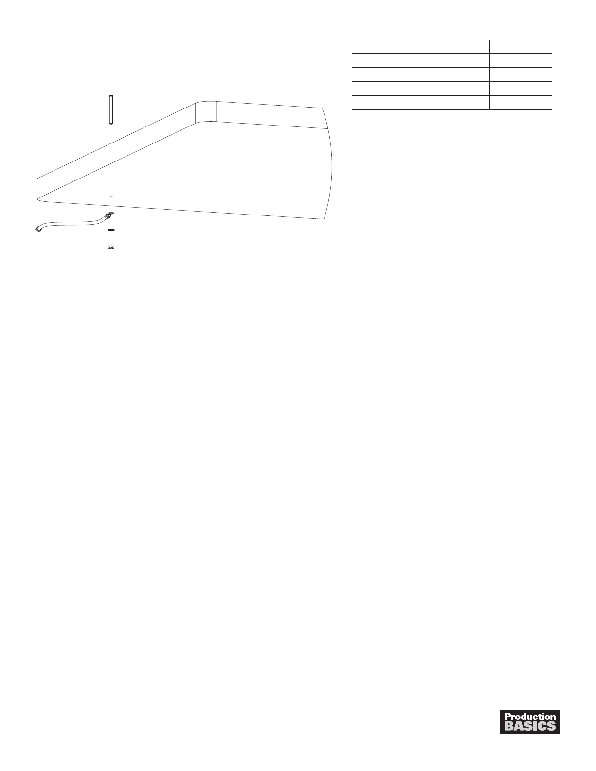
Note: For correct installation of Uprights, ensure•
theworksurfaceispositionedushwithbackof
the Easy-Lift workstation.
Insert a Basic Bolt and washer into each hole on the1. front of the integrated mounting plate. Secure with Basic
Nut. Turn only one revolution. Repeat for other mounting
plate.
Position Uprights against the two (2) Basic Nuts on each2. mounting plate. Turn Basic Bolts 90 degrees clockwise to
grip. Tighten the Bolts. Repeat for other Upright. Ensure
Uprights make contact with both Basic Nuts.
PARTS AND HARDWARE QUANTITY
Uprights 2
3” Bolts 4
Basic Nuts 4
Washers 4
Allen Wrench 1
UPRIGHTS: EASY LIFT, DUAL-LEG
Item Numbers 8539, 8540
Integrated Mounting Plate
1
Production Basics, Inc. Massachusetts, USA 800.318.2770 617-926-8100 Fax: 617-926-8010 www.pbasics.com
Insert Ground Bolt through top of worksurface through1. pre-drilled hole.
Slip ground wire over bolt underneath the worksurface.2. Add the nut and tighten.
Ground other end of wire to electrical ground.3.
For additional information on grounding, contact your4. company’s ESD manager or the ESD Association at
315.339.6937, www.esda.org.
GROUND BOLT
For ESD Laminate Worksurfaces and Shelving PARTS AND HARDWARE QUANTITY
Ground Bolt 1
Ground Wire 1
Washer 2
Nut 1
2
Production Basics, Inc. Massachusetts, USA 800.318.2770 617-926-8100 Fax: 617-926-8010 www.pbasics.com
ASSEMBLY MANUAL
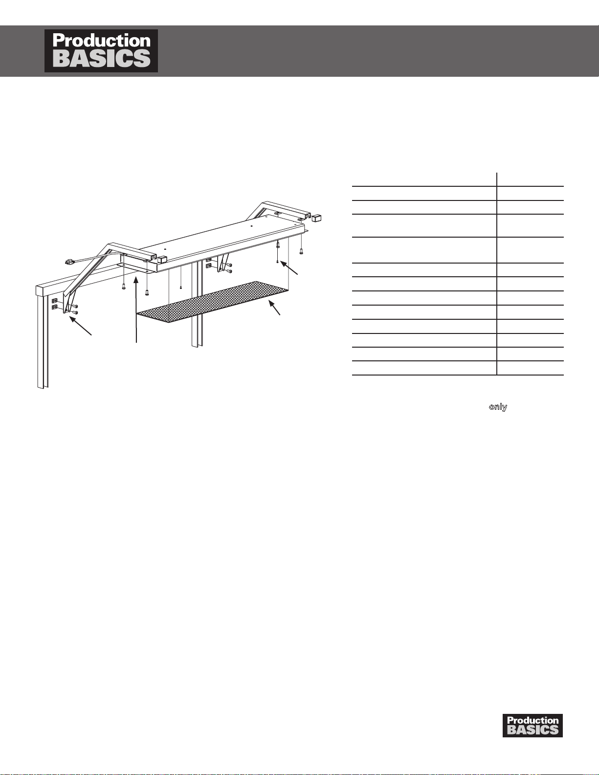
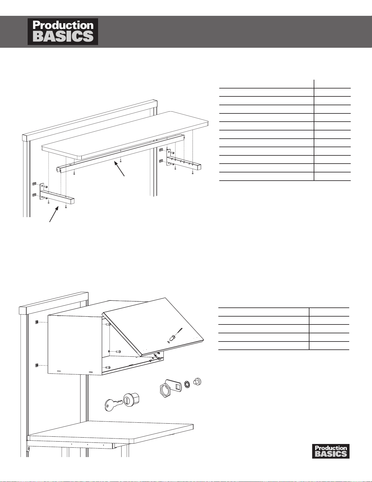
Note: To install Overhead Arms• only, perform
steps 3 & 4.
Unscrew security screws on face of light unit. Remove1. plastic diffuser.
InsertT8lightbulbsintoxture.Pluglightintotest2. correct installation of bulbs. Replace diffuser and security
screws.
Insert two (2) Basic Bolts into mounting plate on3. Overhead Arm. Secure with Basic Nut. Turn only one
revolution. Repeat for other Overhead Arm.
Insert Basic Nuts attached to Overhead Arm mounting4. plate into frame channel of workstation and turn Basic
Bolt 90 degrees clockwise to grip. Top of mounting plate
shouldbeushwithtopofframecrossmember.Tighten
the bolts. Repeat for other Overhead Arm.
Insert a Basic Bolt from bottom into light mounting plate.5. Secure with Basic Nut. Turn only one revolution.
Position light unit with cord facing the frame. Insert Basic6. Nuts attached to light unit into Overhead Arm channel
and turn Basic Bolt 90 degrees clockwise to grip.
Slide the light unit to the desired position. Tighten the7. bolts. Slide End Caps onto front ends of Overhead Arms.
OVERHEAD LIGHT & OVERHEAD ARMS
Item Numbers 8500, 8504, 8505, 8510, 8538
A C C E S S O R I E S
PARTS AND HARDWARE QUANTITY
Overhead Arms 2
End Caps 2
Basic Bolts 4 (Arms only)
8 (With light)
Basic Nuts 4 (Arms only)
8 (With light)
Light Unit 1
Allen Wrench 1
Other Items Needed (not included)
24” T8 bulb for 36” 3
36” T8 bulb for 48” 3
48” T8 bulb for 60” & 72” 3
Phillips head screwdriver
Tape Measure
Diffuser
Overhead Arm
mounting plate
Security Screws
Light Mounting Plate
3

Note: Install Overhead Arms before Tool Trolley•
System.
Insert Basic Bolts into hole on Tool Track and secure1. with Basic Nut.
Position Track spanning the width of the Overhead Arms.2. Insert the Basic Nut into the Overhead Arm channel, turn
bolt 90 degrees and tighten.
Ensure an end cap is secure on each end of the Track
3. and there is a green ‘brake’ positioned on each end of
the track.
Remove security screws, plastic diffuser and light bulb.
1.
Position light unit with cord facing the frame. Attach light2. unit to laminate shelf using wood screws. Pre-drilled
holes are located behind bulb.
If attaching to Universal Shelf, insert bolt througha. shelf and into light. Secure with nut.
If attaching to Storage Cabinet, insert wood screwsb. through inside of light into Cabinet with drill.
Replace light bulbs, diffuser and security screws.
3.
Need Help? Call Assembly Support at 800.318.2770
TOOL TROLLEY SYSTEM
item Numbers 8339, 8340, 8343, 8346
UNDER SHELF LIGHT: LAMINATE AND UNIVERSAL SHELVES
Item Numbers 8523, 8524
Laminate Shelf
Universal Shelf
PARTS AND HARDWARE QUANTITY
Tool Track 1
Trolley with clip 1
Trolley Brake 2
Basic Bolts 4
Basic Nuts 4
End Caps 2
Allen Wrench 1
PARTS AND HARDWARE QUANTITY
Light Unit 1
Wood Screws 2
Bolts 2
Nuts 2
T8 Light Bulbs 1
Other Items Needed (not included)
Phillips head screwdriver or drill
4
Production Basics, Inc. Massachusetts, USA 800.318.2770 617-926-8100 Fax: 617-926-8010 www.pbasics.com
ASSEMBLY MANUAL
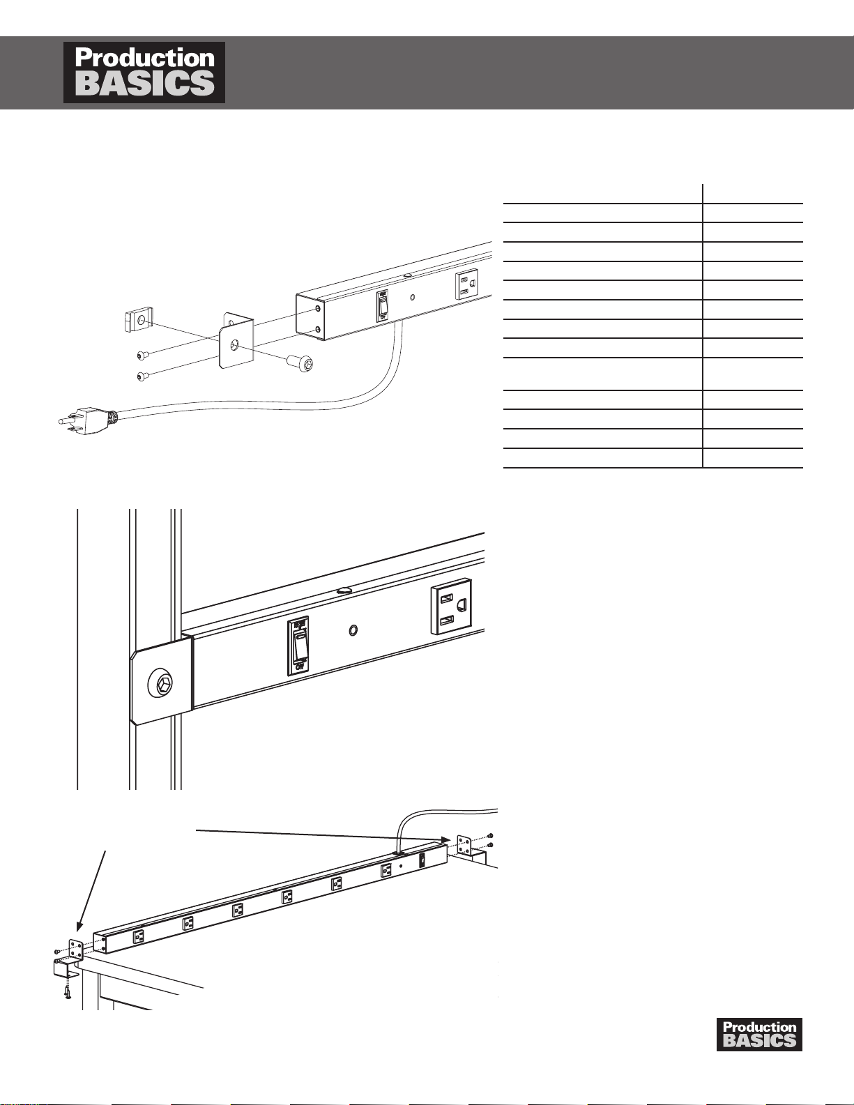
Note: Surface Mount method is not compatible•
with C-Leg Series workstations.
To install Power Rail to an Upright or Frame, attach1. brackets to Power Rail as shown.
Insert a Basic Bolt into bracket. Add a Basic Nut and turn2. one revolution.
Install Power Rail at any height on your Uprights, Frame3. or Overhead Arms.
Alternate mounting to RTW, Easy-Lift or existing work4. table: use enclosed bracket shown below to mount
Power Rail to your worksurface. Secure under the
worksurface with wood screws.
POWER RAIL
Item Numbers 8319-8322, 8324, 8326, 8327
ACCESSORIES
PARTS AND HARDWARE QUANTITY
Power Rail 1
Basic Bolt 2
Basic Nuts 2
Wood Screws 4
Bracket- frame mount 2
Bracket-table mount 2
Bracket bolts 4
Allen Wrench 1
Medium Allen Wrench for bracket
bolts 1
Other Items Needed (not included)
Phillips head screwdriver or drill
Tape measure
Level
Bracket attachment for
surface mount Power Rail
5

Production Basics, Inc. Massachusetts, USA 800.318.2770 617-926-8100 Fax: 617-926-8010 www.pbasics.com
ASSEMBLY MANUAL
Insert a Basic Bolt into the holes on the product’s1. mounting plate. Secure with a Basic Bolt by turning one
revolution.
Insert the nuts into the Frame or Uprights and tighten2. bolts.
Repeat for other side3.
Insert a Basic Bolt into the holes on the product’s1. mounting plate. Secure with a Basic Bolt by turning one
revolution.
Insert the nuts into the Frame or Uprights and tighten2. bolts.
Repeat for other side.3.
GLOBAL INSTALLATION: These instructions apply to the following accessories:
Peg Board Item Numbers 8721-8724
Bin Panel Enclosure Item Numbers 8312-8315
Tack Board Item Numbers 8729, 8730, 8733, 8735
Modesty Panel Item Numbers 8705, 8709, 8712, 8715
Magnetic Dry Erase Board Item Numbers 8716-8719
Multi- Panel Enclosures Item Numbers 8776-8797
GLOBAL INSTALLATION: These instructions apply to the following accessories:
Tool Shelf and Bin Rail Item Numbers 8492-8494
Universal Mount Item Numbers 8640, 8643
Cable Trough Item Numbers 8620-8623
Binder Holder Item Numbers 8352
Peg Board Panel Item Numbers 8626, 8649
Parts Bin Panel Item Numbers 8627, 8639
CRT MonitorTray Item Numbers 8630, 8631
Flat Screen MonitorArm Item Numbers 8632
Air Rail Item Numbers 8330, 8331, 8333, 8336
Bin Rail Item Numbers 8300, 8301, 8303, 8306
ACCESSORIES
PARTS AND HARDWARE QUANTITY
Basic Bolts 4
Basic Nuts 4
Allen Wrench 1
Other Items Needed (not included)
Tape Measure
Level
PARTS AND
HARDWARE QUANTITY
BASIC BOLTS BASIC NUTS
Tool Shelf and Bin Rail 2 2
Universal Mount 2 2
Cable Trough 2 2
Binder Holder 2 2
Parts Bin Panel 2 2
Air Rail 2 2
Bin Rail 2 2
Allen Wrench 1
Other Items Needed
(not included)
Tape Measure
Level
6
Need Help? Call Assembly Support at 800.318.2770
Attach extension to back of Parts Bin Rail by inserting1. a Basic Bolt through hole on the Bin Rail and into
Extension. Repeat for other side. Tighten bolts.
Insert Basic Bolt through mounting plate on Extension,2. secure with a Basic Nut, turning one revolution.
Insert the nuts into the Frame or Uprights and tighten3. bolts.
Insert Basic Bolt into holes on bracket. Secure with a
1. Basic Nut turning one revolution.
Insert Nuts into Frame or Upright and tighten bolts.2. Notches on brackets face inward, as shown. Repeat for
other bracket. Measure or use a level to ensure brackets
are at the same height.
Insert the bar clip into one of 3 positions on the bracket.3. Repeat for other bar clip in the same position.
Add labels, foam or paper rolls to rod and nest rod into4. each bar clip.
Insert Basic Bolt into holes on bracket. Secure with a Basic
1. Nut turning one revolution.
Position brackets on the left and right, as shown. Insert2. Nuts through bracket and into Frame or Upright as shown
in diagram and tighten bolts. Repeat for other bracket.
Measure or use a level to ensure brackets are at the same
height.
Position rail supports as shown. Line up holes on rail3. supports with bracket holes. Insert a handle into the hole
from the inside (recommended) and secure with a kep nut.
To install slide rails, position rails to accommodate your4. circuit boards and insert a threaded stud through the
bottom of the rail support and slide rail. Secure with silver
knob.
BIN RAIL EXTENSION
Item Numbers 8308, 8310
ENCLOSURES: PAPER ROLL HOLDER
Item Numbers 8740-8743
ENCLOSURES: SLIDE LINE
Item Numbers 8770- 8773
Bin Rail Extension
Bar Clip
Rail Support
Slide Rails
Threaded Stud
Bracket
PARTS AND HARDWARE QUANTITY
Basic Bolts 2
Basic Nuts 2
Bin Rail Extension 2
Allen Wrench 1
PARTS AND HARDWARE QUANTITY
Paper Roll Bar 1
Brackets 2
Bar Clip 2
Basic Bolts 4
Basic Nuts 4
Allen Wrench 1
PARTS AND HARDWARE QUANTITY
Slide Rails 2
Brackets 2
Rail Support 2
Basic Bolts 2
Basic Nuts 2
Handles 2
Kep Nut 2
Threaded Stud and Knob 4
Allen Wrench 1
Paper Roll Bar
Brackets
7
Production Basics, Inc. Massachusetts, USA 800.318.2770 617-926-8100 Fax: 617-926-8010 www.pbasics.com
ASSEMBLY MANUAL
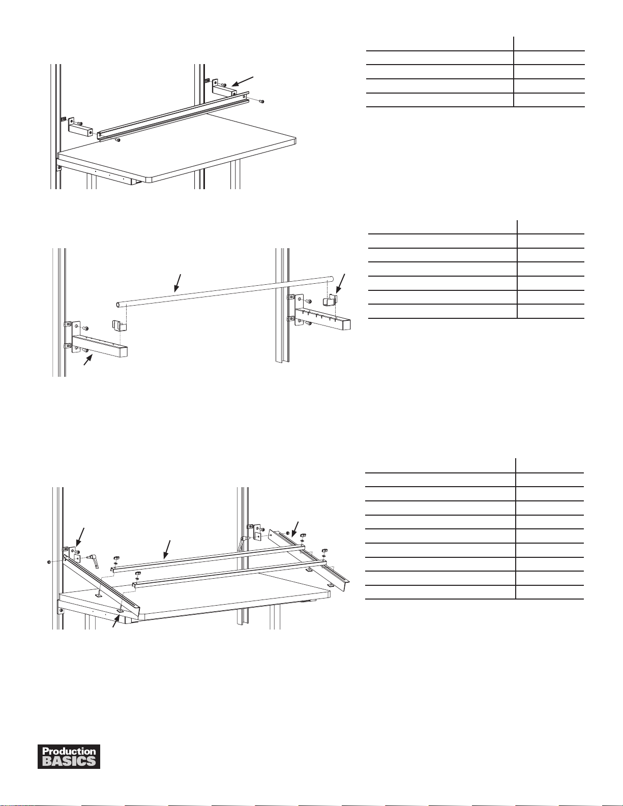
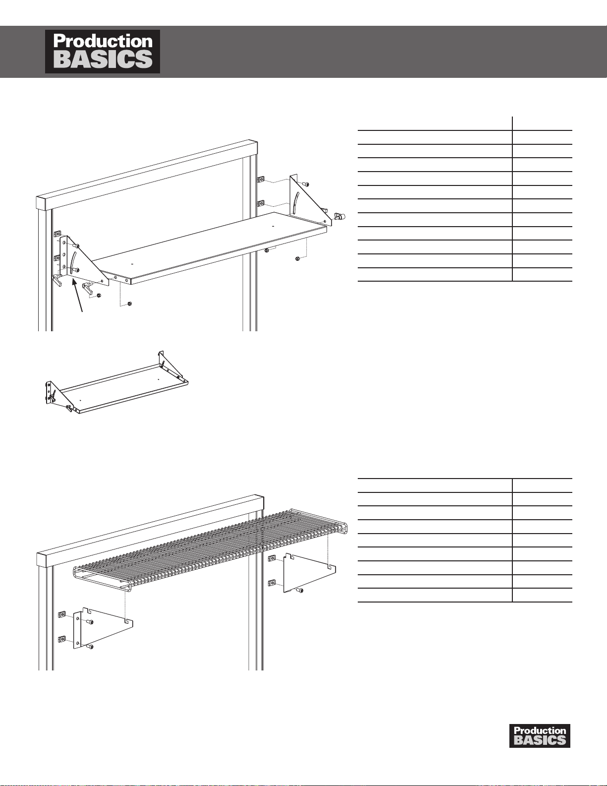
Insert Basic Bolt into holes on bracket. Secure with a1. Basic Nut turning one revolution.
Insert Nuts into Frame or Upright and tighten bolts.2. Notches on brackets face inward. Repeat for other
bracket. Measure or use a level to ensure brackets are
at the same height.
Insert the shelf cross bar into frontmost position3. (recommended).
Place shelf on top of bracket installation and secure with
4. wood screws underneath the shelf.
SHELVING: LAMINATE SHELF
Item Numbers 8417-8439, 8449-8461
ACCESSORIES
PARTS AND HARDWARE QUANTITY
Laminate Shelf 1
Brackets 2
Cross Bar 1
Basic Bolts 4
Basic Nuts 4
Wood Screws 8
Allen Wrench 1
Other Items Needed (not included)
Phillips head screwdriver or drill
Tape Measure
Level
Bracket
Shelf Cross Bar
Open Storage Cabinet and slide door back.1.
Insert Basic Bolts into the holes on the inside corners2. of the Cabinet. Secure with a Basic Nuts and turn one
revolution.
Position Storage Cabinet on frame and turn bolts 903. clockwise to grip channel. Tighten bolts.
To install the lock, push the lock mechanism through4. the hole in front right side of the drawer. Assemble as
shown. Ensure the unthreaded part of the lock and the
key teeth face upwards.
PARTS AND HARDWARE QUANTITY
Storage Cabinet
Lock mechanism
Basic Bolts
Basic Nuts
Allen Wrench
STORAGE CABINET
Item Numbers 8551-8553
Lock Detail
1
1
4
4
1
8
Production Basics, Inc. Massachusetts, USA 800.318.2770 617-926-8100 Fax: 617-926-8010 www.pbasics.com
ASSEMBLY MANUAL
Insert Basic Bolt into holes on shelf bracket. Secure with1. Basic Nut and turn only one revolution. Repeat for other
side of bracket.
Position brackets as shown. Insert Basic Nuts attached2. to shelf bracket tabs into frame channel. Turn Basic Bolt
90 degrees clockwise to grip.
Slide brackets to desired height. Measure or use a level3. to ensure brackets are at the same height.
Position shelf to line up with adjustment slots on bracket.4. Insert handle from outside into adjustment slots and
secure with star washer and nut. Repeat for all four
handles.
Insert Basic Bolt into holes on shelf bracket. Secure with
1. Basic Nut and turn only one revolution. Repeat for other
bracket.
Position brackets as shown. Insert Basic Nuts attached2. to shelf bracket tabs into frame channel. Notches
indicate top of bracket. Turn Basic Bolt 90 degrees
clockwise to grip. Measure or use a level to ensure
brackets are at the same height.
Attach the shelf to the bracket. Nest shelf in notches and3. pull forward to lock in place.
ACCESSORIES
PARTS AND HARDWARE QUANTITY
Laminate Shelf 1
Brackets 2
Basic Bolts 4
Basic Nuts 4
Handles 4
Kep Nuts 4
Allen Wrench 1
Other Items Needed (not included)
Phillips head screwdriver or drill
Tape Measure
Level
Universal Shelf- inverted with a 1” lip.
Adjustment Slot
SHELVING: WIRE
Item Numbers 8400, 8401, 8403, 8406 PARTS AND HARDWARE QUANTITY
Wire Shelf 1
Brackets 2
Cross Bar 1
Basic Bolts 4
Basic Nuts 4
Allen Wrench 1
Other Items Needed (not included)
Tape Measure
Level
Note:UniversalShelfcanbeinstalledasat•
surface or sloped with a 1-inch lip.
SHELVING: UNIVERSAL
Item Numbers 8390-8397, 8410-8416
Bracket
9

Need Help? Call Assembly Support at 800.318.2770
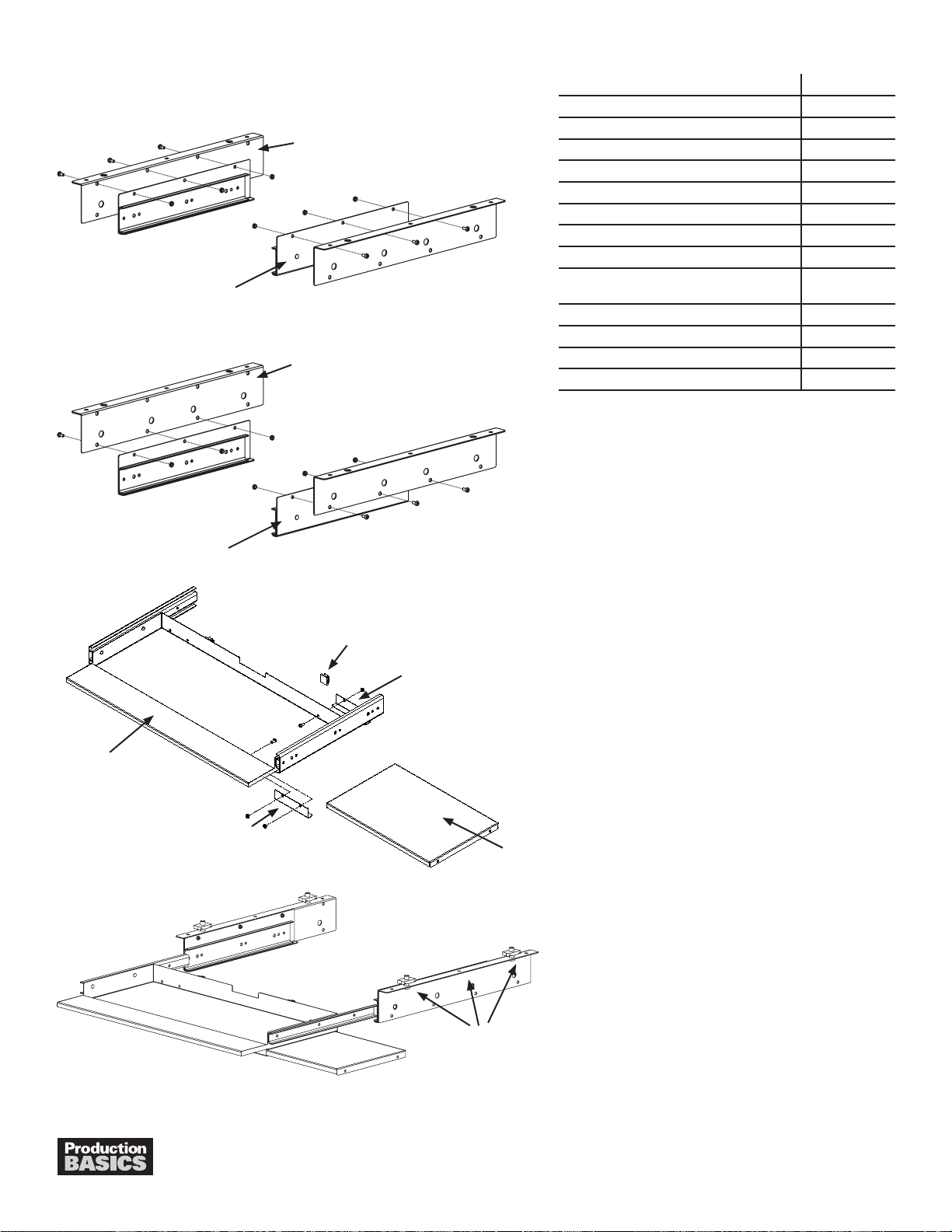
Remove the drawer from the chassis by pushing down1. on the black tabs on both sides of the drawer and pull
the drawer forward. If installing cabinet, start with Step 2.
Using the allen wrench, punch out the lock knock-out on2. the front side of the drawer or cabinet. Assemble lock
mechanism as shown. Ensure the unthreaded part of the
lock and key teeth face upward.
Insert a Basic Bolt from the inside of the drawer or3. cabinet chassis and secure with Basic Nut, turning one
revolution. Repeat for all four corners.
Insert attached Basic Nuts into Worksurface Support4. Rail channel and turn Basic Bolt 90 degrees clockwise to
grip. Position chassis under worksurface as desired and
tighten bolts.
If stacking items, insert small bolt from above intoa. the pre-drilled hole in bottom back of chassis and
lightly secure with nut and washer.
Align second chassis’ back keyhole slot with nutsb. and pull forward. This will help you support the
drawer while securing other nuts and bolts for
stacking drawers.
Give all nuts and bolts a final tightening.c.
Push in drawer slides on chassis and insert complete5. drawer into chassis.
DRAWERS & SUSPENDED CABINET:
C-LEG AND EASY-LIFT, DUAL LEG UNITS
Item Numbers 8600, 8605, 8607, 8610, 8613, 8615, 8617 PARTS AND HARDWARE QUANTITY
Drawer 1
Drawer or Cabinet Chassis 1
Lock Mechanism 1
Keys 2
Basic Bolts 4
Basic Nuts 4
Bolts (used for stacking drawers) 4
Kep Nuts (used for stacking drawers) 4
Washers (used for stacking drawers) 4
Allen Wrench 1
Other Items Needed (not included)
Phillips head screwdriver
Open end wrench
Black tabs- push in to release drawer
Keyhole details for
stacking drawers
Use hole set for hanging
first drawer -step 3
10

Production Basics, Inc. Massachusetts, USA 800.318.2770 617-926-8100 Fax: 617-926-8010 www.pbasics.com
ASSEMBLY MANUAL
Keyboard tray is positioned between monitor and1. mounting plate. Use provided screws to secure all 3 items
in order shown.
To adjust tension and swivel of Flat Screen Monitor Arm,2. remove plastic end caps and use included T-handle
wrench to adjust.
Before assembling the keyboard support with the
1. enclosed instructions, attach mounting plate to adapter
using button head bolts and nuts provided. See diagram
at left.
Insert a Basic Bolt into the corner holes of the adapter2. and secure with a Basic Nut. See diagram at left. For
RTW Tables, proceed to step 4a.
Insert nuts attached to adapter into Worksurface Support3. Rails on your workstation, as shown. Turn Basic Bolt 90
degrees clockwise to grip. Tighten the bolts.
Proceed with enclosed instructions for your keyboard.4.
For RTW Tables, insert wood screws through holesa. on tabs to attach Keyboard Support to underside of
worksurface.
Secure the wrist support by inserting plastic screws from
5. the bottom and tighten.
FLAT SCREEN MONITOR ARM WITH ADD-ON KEYBOARD TRAY
Item Numbers 8632 + 8633
ADJUSTABLE KEYBOARD SUPPORT
Item Numbers 8680
PARTS AND HARDWARE QUANTITY
Keyboard Tray 1
Phillips head screws 4
Other Items Needed (not included)
Phillips Head Screwdriver
ACCESSORIES
PARTS AND HARDWARE QUANTITY
Adapter Plate 1
Mounting Plate 1
8/32 Button head bolt 6
Nuts 6
Washers 6
Wood screws 4
Basic Bolts 4
Basic Nuts 4
Allen Wrench 1
Small Allen Wrench 1
See Step 1
Adapter Plate
See Step 4a for RTW Tables,
Easy-Lift 4-Post
See Step 2 for C-Leg,
Easy-Lift Dual-Leg
Mounting Plate
Adapter Plate
11
Need Help? Call Assembly Support at 800.318.2770
Using three (3) 3/8” nuts and bolts, assemble Upper and1. Lower Side Brackets as shown for right and left brackets,
according to your style of workstation (C-Leg, Easy-Lift,
RTW or PedSys). Set aside until step 4.
Choose right or left side for mouse tray. Using two (2)2. 3/8” bolts, hex nuts and washers, install the mouse pad
bracket onto the keyboard tray under the back lip of the
wrist rest. Slide the tray onto the bracket and repeat
for the rear mouse pad bracket with tray in place. The
mouse tray should slide freely. A lip on the tray acts as
a stop.
Attach adhesive backed cable clip to back of keyboard3. tray. These hold your mouse and keyboard wires in
place.
For C-Leg and Easy-Lift workstations insert a Basic4. Bolt through the two (2) large holes on top of each
bracket from step 1. Secure with a Basic Nut. Turn one
revolution.
For RTW, use wood screws to attach to underside ofa. worksurface. Go to Step 6.
Position the keyboard under the workstation. Insert the
5. Basic Nuts attached to the bracket into the Worksurface
Support Rail and tighten the bolts.
Slide keyboard onto left and right side brackets as6. shown.
PARTS AND HARDWARE QUANTITY
Upper Side Bracket 2
Lower Side Bracket 2
Basic Bolts 4
Basic Nuts 4
Keyboard Drawer 1
Cable Clip 2
Mouse Pad Bracket 2
Mouse Tray 1
Nuts & 3/8” Bolts for Upper and Lower
Side Brackets, Mouse Pad Bracket 10
Wood Screws 6
Small Allen Wrench 1
Other Items Needed (not included)
Phillips head drill
KEYBOARD DRAWER
item Number 8681
Upper side Bracket- C-leg/Easy-Lift Dual Leg, left side
Lower Side Bracket C-Leg/EasyLift Dual Leg, right side
Upper side Bracket- RTW/Easy-Lift 4-Post, left side
Lower Side Bracket RTW/Easy-Lift 4-Post, PedSys, left side
Cable Clip
Mouse Tray
Completed Keyboard Drawer for
C-Leg/Easy Lift Dual Leg
See Step 4a for RTW Table,
Easy-Lift 4-post, PedSys
Wrist Rest
Rear Mouse Pad Bracket
Mouse Pad Bracket
12
This manual suits for next models
1
Table of contents
Other Production Basics Indoor Furnishing manuals


Popular Indoor Furnishing manuals by other brands


Wisteria Lane
Wisteria Lane KX-AL01-1 instruction manual

BDI
BDI CLOUD 9 1183 instruction manual

VONDOM
VONDOM SUAVE 44310 Assembling instructions

Bestway
Bestway P3073 owner's manual

Home Decorators Collection
Home Decorators Collection Ellia HDC30MFV Use and care guide

Furinno
Furinno 11013 Assembly instruction

Furniture of America
Furniture of America YNJ-15409 Assembly instructions

CHIEF
CHIEF CM6QH SERIES installation instructions

Keter
Keter PIU-TALL Assembly instructions

Richard Lampert
Richard Lampert EIERMANN 1 Assembly instruction

John Lewis
John Lewis 836 78003 manual

Badger Basket
Badger Basket 09130 Assembly instructions