Prodys ProntoNet User manual

Feb 2012
Rev 2.2

Prodys S.L. Tel: +34 91 6896880 Fax: +34 91 6943777 Email: sales@prodys.net Web: www.prodys.com
Page 2
Index
Index ................................................................................ 2
CE Declaration of Compliance.................................................. 6
Introduction....................................................................... 7
I.1 The set of Manuals .................................................................. 7
I.2 The Application Notes .............................................................. 8
I.3 The Hardware and Reference Manual ............................................ 8
Installation Guide ................................................................ 9
II.1 Initial checks ........................................................................ 9
II.2 Installation .......................................................................... 9
II.3 The rear panel .....................................................................10
II.3.1 Power.............................................................................10
II.3.2 Communication Interfaces ....................................................11
II.3.2.1. Ethernet port –the LAN Connector .....................................11
II.3.2.2. ISDN Port ....................................................................13
II.3.2.3. X21 Port .....................................................................14
II.3.3 RS 232 Ports .....................................................................15
II.3.4 GPIO Port ........................................................................16
II.3.4.1. Inputs ........................................................................17
II.3.4.2. Outputs......................................................................17
II.3.5 Audio interfaces ................................................................17
II.3.5.1. Analog audio I/O ...........................................................17
II.3.5.2. AES/EBU Interface .........................................................17
II.3.6 Microswitches ...................................................................18
An introduction to the Front Panel .........................................19
III.1 Display..............................................................................20
III.1.1 STATUS SCREEN ................................................................20
III.2 Control Keys .......................................................................25
III.2.1 The CALL 1 and CALL 2 keys..................................................25

Prodys S.L. Tel: +34 91 6896880 Fax: +34 91 6943777 Email: sales@prodys.net Web: www.prodys.com
Page 3
III.2.1.1. Establishing a call when ProntoNet is configured as an IP
Unicast/Multicast codec.............................................................26
III.2.1.2. Establishing a call when ProntoNet is configured as an IP Multi-
Unicast codec (NET = IP) ............................................................27
III.2.1.3. Establishing a call when ProntoNet is configured as an ISDN codec
(NET = ISDN)...........................................................................28
III.2.1.4. Establishing a call when ProntoNet is configured as an X21 codec
(NET = X21)............................................................................28
III.2.2 The INFO key ...................................................................29
III.2.2.1. Screen 1: Audio input VU meters .......................................29
III.2.2.2. Screen 2: Audio output VU meters .....................................29
III.2.2.3. Screen 3: Decoding algorithm ...........................................30
III.2.2.4. Screen 4: encoding algorithm ...........................................30
III.2.2.5. Screen 5: LAN port configuration parameters .......................31
III.2.2.6. Screen 6: Net configuration .............................................31
III.2.2.7. Screen 7: Audio Input Configuration ..................................32
III.2.2.8. Screen 8: GPIO and Serial Port bit rate................................32
III.2.3 The BOOK Key ..................................................................32
The Front Panel Menu .........................................................34
IV.1 The Controls: Navigation keys ..................................................34
IV.2 Main Menu .........................................................................35
IV.3 NET: Selecting a communications port. .......................................35
IV.3.1 IPCODEC ........................................................................36
IV.4 ENC: Encoder algorithm selection menu ......................................37
IV.4.1 Configuration of Encoder 1...................................................37
IV.4.2 PCM ..............................................................................38
IV.4.3 G711 .............................................................................39
IV.4.4 G722: ............................................................................39
IV.4.5 MPEG Layer II...................................................................39
IV.4.6 MPEG Layer III ..................................................................39
IV.4.7 AAC 2,4 LC ......................................................................40
IV.4.8 AAC LD...........................................................................41
IV.4.9 AAC HE ..........................................................................41
IV.4.10 AAC ELD ........................................................................41
IV.4.11 aptX ............................................................................42
IV.4.11.1. STD APTX .................................................................42
IV.4.11.2. ENH APTX .................................................................43
IV.5 Configuration of Encoder 2......................................................44
IV.6 CONF: General configuration Menu ............................................46

Prodys S.L. Tel: +34 91 6896880 Fax: +34 91 6943777 Email: sales@prodys.net Web: www.prodys.com
Page 4
IV.6.1 CONF –AUD .....................................................................46
IV.6.1.1. AUDIO IN....................................................................47
IV.6.1.2. AUDIO LEVELS .............................................................48
IV.6.2 CONF-PORTS ....................................................................48
IV.6.2.1. LAN..........................................................................48
IV.6.2.2. ISDN .........................................................................51
IV.6.2.3. X21 ..........................................................................54
IV.6.2.4. RS232 .......................................................................54
IV.6.3 CONF-SYS .......................................................................55
IV.6.3.1. Loop.........................................................................55
IV.6.3.2. PLL ..........................................................................56
IV.6.3.3. BACKUP .....................................................................56
IV.6.3.4. FAN..........................................................................58
IV.6.3.5. AUXDATA ...................................................................59
IV.6.3.6. KEYPAD .....................................................................60
IV.6.3.7. BUZZER .....................................................................61
IV.6.3.8. RESET .......................................................................61
IV.6.4 CONF-BOOK .....................................................................61
IV.6.5 CONF-STREAMING ..............................................................63
IV.6.6 CONF-PRESETS .................................................................63
IV.7 INF ..................................................................................64
IV.7.1 VERSIONS........................................................................64
IV.7.2 TA ................................................................................65
IV.7.3 AUX DATA .......................................................................65
Technical Specifications.......................................................66
V.1 Audio Interfaces ...................................................................66
V.1.1 Stereo Audio Inputs ............................................................66
V.1.2 Stereo Audio Outputs ..........................................................66
V.2 Audio properties*..................................................................67
V.3 Compression........................................................................67
V.4 Communications Ports ............................................................67
V.4.1 ISDN ..............................................................................67
V.4.2 LAN port .........................................................................67
V.4.3 GPIO Port ........................................................................67
V.4.4 RS232 Port.......................................................................68
V.4.5 X21 Port..........................................................................68
V.5 Power Supply.......................................................................68
V.5.1 Main ..............................................................................68
V.5.2 Secondary (Optional) ..........................................................68

Prodys S.L. Tel: +34 91 6896880 Fax: +34 91 6943777 Email: sales@prodys.net Web: www.prodys.com
Page 5
V.6 Dimensions and Weight ...........................................................68
V.7 Environment........................................................................69
Double LAN Interface ..........................................................70
VI.1 Double LAN option................................................................70
VI.2 Types of data: audio & control .................................................71
VI.3 Configuration......................................................................72
VI.4 Ethernet Interface specification ...............................................74
VI.5 LAN 2 Down status warning on the display....................................75
VI.6 Disabing LAN2 Interface .........................................................76
Prodys S.L. Tel: +34 91 6896880 Fax: +34 91 6943777 Email: sales@prodys.net Web: www.prodys.com
Page 6
CE Declaration of Compliance
Procesamiento Digital y Sistemas S.L., hereby declares that ProntoNet bearing
the CE168X parking are in compliance with Electromagnetic Compatibility
Directive (89/336/EEC), and the Low Voltage Directive (72/23/EEC) of the
European Union.
A “Declaration of conformity” for ProntoNet is available on file at Prodys offices in
CAUTION
ProntoNet uses a Lithium battery.
Danger of explosion if battery is incorrectly replaced. Replace only with the same
or equivalent type recommended by the manufacturer. Dispose of used batteries
according to the manufacturers instructions.
Your product is designed and manufactured with high quality
materials and components, which can be recycled and reused.
When this crossed-out wheeled bin symbol with black bar underneath
is attached to a product it means that product is covered by the
European Directive 2002/96/EC.
Please, inform yourself about the local separate collection system for
electrical and electronic products.
Please act according to your local rules and do not dispose of your old
products with your normal household waste. The correct disposal of
your old product will help prevent potential negative consequences for
the environment and human health.

Prodys S.L. Tel: +34 91 6896880 Fax: +34 91 6943777 Email: sales@prodys.net Web: www.prodys.com
Page 7
INTRODUCTION
ProntoNet expands the Prodys audio codec family building on the features
provided in previous models. ProntoNet extends its performance possibilities as
dual audio codec by supporting MPEG 2/4 AAC LC, MPEG 4 LD, ELD & HE and
apt-XTM amongst its standard algorithms as well as bidirectional uncompressed
audio transmission over IP.
ProntoNet is also a Multi-network audio codec that can be used in different
industry standard types of communication networks:
ISDN 1-BRI (U or S/T interfaces).
X21 synchronous data transmission links (Digital Leased Line: DLL).
LAN connector, 10/100Base-TX Ethernet interface for audio transmission and
control (audio streaming over private IP networks or Internet)
3G/3.5G mobile through a USB modem.
I.1 The set of Manuals
The Prodys IP Family User Manual is applicable to most of the common features
provided by the Prodys IP Family of codecs.
For some specific features or restrictions, the user is referred to the proper
Hardware and Reference Manual applicable to the codec in use. Installation
requirements, physical and electrical parameters are also included in this
document.
Hardware and Reference Manuals are available for:
ProntoNet
ProntoNet LC
Chapter I

Prodys S.L. Tel: +34 91 6896880 Fax: +34 91 6943777 Email: sales@prodys.net Web: www.prodys.com
Page 8
ProntoNet IP Decoder
Nereus
Nereus One
Nomada IP W
Nomada IP XL
If several Prodys IP Family codecs are managed by means of the ProdysControl
application please refer to the ProdysControl Manual as well.
Prodys IP codecs provide the user with a control protocol which allows the user
to develop customized management software. The control interface for this
protocol is either the RS232 serial port or the Ethernet port. For detailed
description please refer to the Prodys IP Family codec SDK User’s Manual.
I.2 The Application Notes
For specific subjects, Applications Notes and release update (What is new,
ChangeLog…) the user is kindly referred to check our download area at
www.prodys.net or contact support@prodys.net
I.3 The Hardware and Reference Manual
The information is arranged as follows:
Chapter II –Installation Guide.
This chapter provides hardware requirements and instructions for installing
the ProntoNet unit.
Chapter III –An introduction to the Front Panel.
ProntoNet can be configured and controlled from the controls located on its
frontal panel. This chapter describes an introduction to this user interface.
Chapter IV –The Front Panel Menu.
This chapter describes the front panel menu path, the associated options and
parameters.
Appendix A –Technical Specifications.
Technical details are described in this chapter.

Prodys S.L. Tel: +34 91 6896880 Fax: +34 91 6943777 Email: sales@prodys.net Web: www.prodys.com
Page 9
INSTALLATION GUIDE
This chapter describes the ProntoNet hardware and user installation.
The installation and servicing instructions in this manual are for use by qualified personal.
II.1 Initial checks
Before unpacking the unit please check its packaging for any signs of damage or
mishandling during transportation. Report any damage to the shipping company
immediately. Unpack the unit carefully, if you find any damage or the unit does
not work correctly, you should contact Prodys or its distributor as soon as
possible.
II.2 Installation
The ProntoNet is designed to be housed in a standard 19” rack. The unit is
44.45mm high (1U, or 1.75 inches). When choosing a suitable place for
installation, please bear the following in mind:
The position must allow for easy connection of cables to the back of
the unit.
The front panel must also be accessible, both for connections and to
be able to see the Display, keyboard and LED indicators.
The air vents must not be obstructed.
We do not recommended that the unit be mounted directly above
other equipment, especially ones that generate a lot of heat.
Chapter II

Prodys S.L. Tel: +34 91 6896880 Fax: +34 91 6943777 Email: sales@prodys.net Web: www.prodys.com
Page 10
II.3 The rear panel
The majority of the connections of the ProntoNet are found on the back panel.
They are grouped together according to their function, as below:
II.3.1 Power
On the back panel you will find the main power inlet and the fuse holder. The
ProntoNet unit is designed to take AC universal power, from 100 to 240 VAC with
frequency between 50Hz and 60Hz.
You will also find a fuse holder that holds two fuses, one for each phase of input.
When it is necessary to replace either fuse, it is important to make sure that it
complies with the technical specifications outlined below that will ensure
adequate protection.
Fuse requirements:
Fuse type:
Type T
Amps
2A
Power
250V
ATTENTION –CHANGING THE FUSE
Disconnect the power cable BEFORE changing the fuse.
24 OR 48 VDC SECONDARY POWER SOURCE
THIS IS OPTIONAL AND DOES NOT COME FITTED AS STANDARD.
The unit will switch automatically from the primary power source to the
back-up power source in the event of a cut in the primary power supply.
Power
communication
interfaces
GPIO Port
RS232
Port
Audio (analog & AES/EBU)
Prodys S.L. Tel: +34 91 6896880 Fax: +34 91 6943777 Email: sales@prodys.net Web: www.prodys.com
Page 11
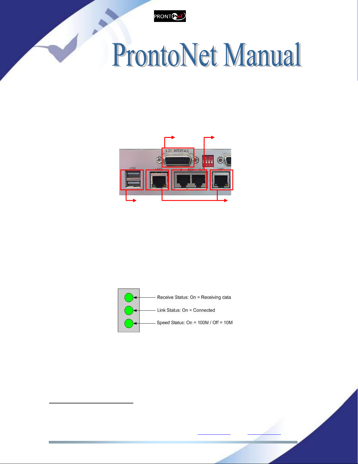
II.3.2 Communication Interfaces
The ProntoNet is equipped with three different communication interfaces –
Ethernet, ISDN and X21 plus two USB1ports where different communications
devices such as 3G modems can be inserted. These are all accessed on the rear
panel, as shown in the following diagram:
II.3.2.1. Ethernet port –the LAN Connector
The LAN socket is a standard 10/100Base-Tx (10/100 Mbps) Ethernet connection
that takes the typical RJ45 plug2. Through this Ethernet port it is possible to
transmit and receive audio, as well as manage the equipment. Next to the
socket there are three LEDs that indicate different states for the connection and
these are very useful in problem-solving situations.
LAN LED’s:
Connection to a Hub or Switch
In the majority of cases you can simply connect the unit’s LAN port to your
Ethernet network’s Hub or Switch using an Ethernet cable (CAT5). In this
case you should use a standard ‘straight-through’ Ethernet cable (not a
‘cross-over’ cable). This kind of cable can normally be found in any IT shop.
In any case, this cable is described in more detail below:
1USB interfaces are optional and are provided within the double Ethernet option.
2Refer also to the appendix if the codec includes a double Ethernet option.
LAN Ethernet
PORT
ISDN
X21
USB

Prodys S.L. Tel: +34 91 6896880 Fax: +34 91 6943777 Email: sales@prodys.net Web: www.prodys.com
Page 12
Connection to a PC
In some cases, such as when you configure the equipment, it is possible
that you will want to connect the unit directly to a PC. In this case the PC
must have a free Ethernet port to connect to and you must use a ‘cross-
over’ Ethernet cable. Again, any good IT shop will stock these cables. This
time the wiring is as follows:

Prodys S.L. Tel: +34 91 6896880 Fax: +34 91 6943777 Email: sales@prodys.net Web: www.prodys.com
Page 13
II.3.2.2. ISDN Port
The ProntoNet incorporates an ISDN terminal adapter that allows connection to
a basic ISDN line (2B+D). It supports different ISDN protocols (EURO_ISDN,
DMS100, AT&T 5ESS and NAT1). To connect there are two RJ45 connectors: one
for connecting to an S/T interface and the other for connecting to a U interface.
Pin
S/T Connector
U Connector
1
NC
NC
2
NC
NC
3
Tx +
NC
4
Rx+
RING
5
Rx-
TIP
6
Tx-
NC
7
NC
NC
8
NC
NC
The U connector is only available if an NT1 interface is installed.
The NT1 interface is optional and is not supplied as standard.
When the ProntoNet is connected to a basic rate interface with bus configuration
and the unit is the termination point, it must be loaded with 100 Ohm resistors.
These may be already fitted in the connection socket, if you do not have external
termination, the ProntoNet has jumpers available internally that can be set to
terminate the ISDN line. The jumpers are found next to the RJ45 connectors.
P2 P3
100RESISTORS CONNECTED
Prodys S.L. Tel: +34 91 6896880 Fax: +34 91 6943777 Email: sales@prodys.net Web: www.prodys.com
Page 14
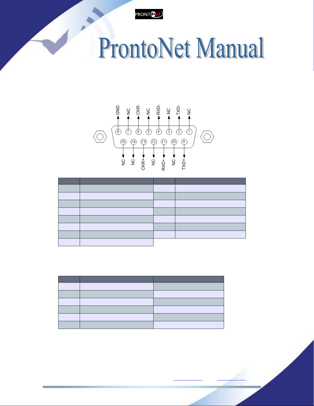
II.3.2.3. X21 Port
The X21 Port allows the transmission and reception of audio via a dedicated
digital connection. The socket is the standard 15 ways sub-D with the following
connections:
Pin
Function
Pin
Function
1
NC
9
Transmit Data TxD+
2
Transmit Data TxD-
10
NC
3
NC
11
Receive Data RxD+
4
Receive Data RxD-
12
NC
5
NC
13
Clock +
6
Clock -
14
NC (Internally used)
7
NC (Internally used)
15
NC
8
GND
To connect a V35 port one must bear in mind the following correlation between
signals:
Pin
X21 ProntoNet
V35 Signal
2
Transmit Data TxD-
P
9
Transmit Data TxD+
S
4
Receive Data RxD-
R
11
Receive Data RxD+
T
6
Clock -
V
13
Clock+
X

Prodys S.L. Tel: +34 91 6896880 Fax: +34 91 6943777 Email: sales@prodys.net Web: www.prodys.com
Page 15
II.3.3 RS 232 Ports
There are two RS232 ports for use as auxiliary data ports. These ports allow the
transmission and reception of data along with encoded audio. Port A is always
ready. Port B is only available if the ProntoNet is configured as a DUAL Codec,
therefore able to operate two totally independent communication channels3.
Note that these sockets are RJ45 connections, as opposed to the typical 9-pin
sub-D connections. To make the conversion between RJ45 and RS232 there are
modular connectors available that should be wired as follows:
S-Cluster
RJ45
Connector
9-pin female
D-sub
Connector
1 (NC)
1
2 (Rx)
3
3 (GND)
5
4 (NC)
4
5 (NC)
6
6 (GND)
7
7 (Tx)
2
8 (NC)
8
1,4,5,8 must be unconnected
The ports are always set to 8 DATA bits, NO parity, 1 START bit and 1 STOP bit.
The bit rate can be adjusted to between 300 and 9600 bps via software.
The ProntoNet acts as a DCE device, therefore the connection to each of the
RS232 ports is wired in the following way:
ProntoNet –Pin 7 connector RJ45.........................Pin 2 PC
ProntoNet –Pin 2 connector RJ45.........................Pin 3 PC
ProntoNet –Pin 3,6 connector RJ45......................Pin 5 PC
The ProntoNet ignores hardware handshaking signals.
3DUAL codec: ProntoNet is able to operate as a DUAL codec over ISDN and over IP (when
configured in ‘DOUBLE’ mode).
Prodys S.L. Tel: +34 91 6896880 Fax: +34 91 6943777 Email: sales@prodys.net Web: www.prodys.com
Page 16
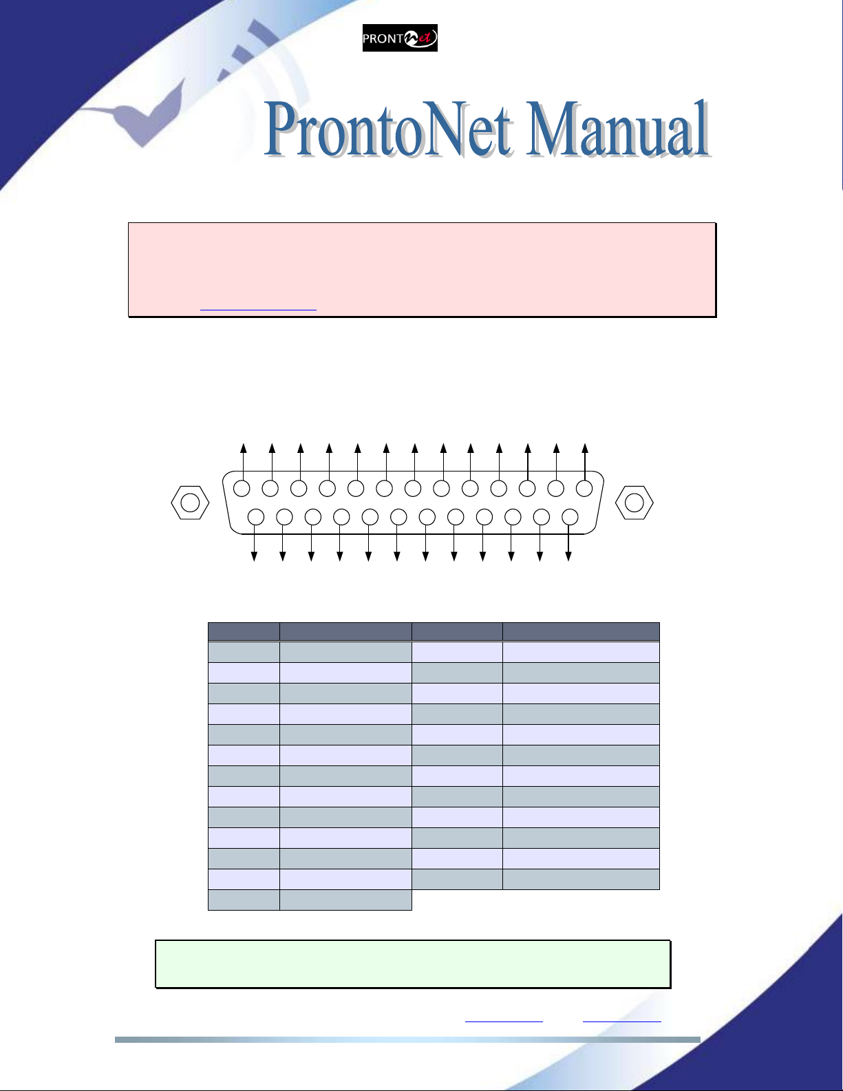
II.3.4 GPIO Port
WARNING
GPIO has been modified in ProntoNet with serial number 8938/00250 or higher.
Since this production, the GPIO is provided with 7 inputs and 7 outputs. Please
A sub-D 25 ways socket provides a general purpose connection with 7 inputs and
7 outputs. The connections must be wired according to the following diagram:
12345
15
9 678
1617181920
10111213
25 24 23 22 21 14
NC
NC
NC
NC
OUT1
OUT3
OUT5
OUT7
NC
OUT2
OUT4
OUT6
GND
VCC
NC
IN2
IN4
IN6
NC
NC
IN1
GND
IN3
IN5
IN7
Pin
Function
Pin
Function
1
+5VDC
14
IN 7
2
IN 6
15
IN 5
3
IN 4
16
IN 3
4
IN 2
17
IN 1
5
NC
18
NC
6
NC
19
NC
7
GND
20
GND
8
OUT 7
21
OUT 6
9
OUT 5
22
OUT 4
10
OUT 3
23
OUT 2
11
OUT 1
24
NC
12
NC
25
NC
13
NC
Pin 1 is connected to +5 volts. If you need it , run this power supply through
your device with a resistor in series to limit the maximum current to 300 mA.
Prodys S.L. Tel: +34 91 6896880 Fax: +34 91 6943777 Email: sales@prodys.net Web: www.prodys.com
Page 17
II.3.4.1. Inputs
The inputs are active for grounding (active low).
II.3.4.2. Outputs
The outputs are “open collector”. They allow an output of 5VDC on one pin to
facilitate interconnection with the outputs. Each output supports up to a
maximum of 40VDC / 40 mA and will require a pull-up resistor to function with
other logic inputs. An appropriate value is 2.2 Kohms.
II.3.5 Audio interfaces
II.3.5.1. Analog audio I/O
The analog audio I/O is connected through the XLR connections on the rear
panel. The wiring conforms to the following scheme:
Pin
Function
1
Ground
2
Audio+
3
Audio-
II.3.5.2. AES/EBU Interface
An AES/EBU interface is available via three XLR connectors on the rear panel of
the unit. The central connector provides the option to connect an externally
synchronised signal. The user can select via software if the digital output is to
synchronise with the audio input or with an external sync signal. The connectors
are wired in the following way:
Pin
Function
1
Ground
2
AES/EBU IN-OUT-SYNC +
3
AES/EBU IN-OUT-SYNC -
Prodys S.L. Tel: +34 91 6896880 Fax: +34 91 6943777 Email: sales@prodys.net Web: www.prodys.com
Page 18
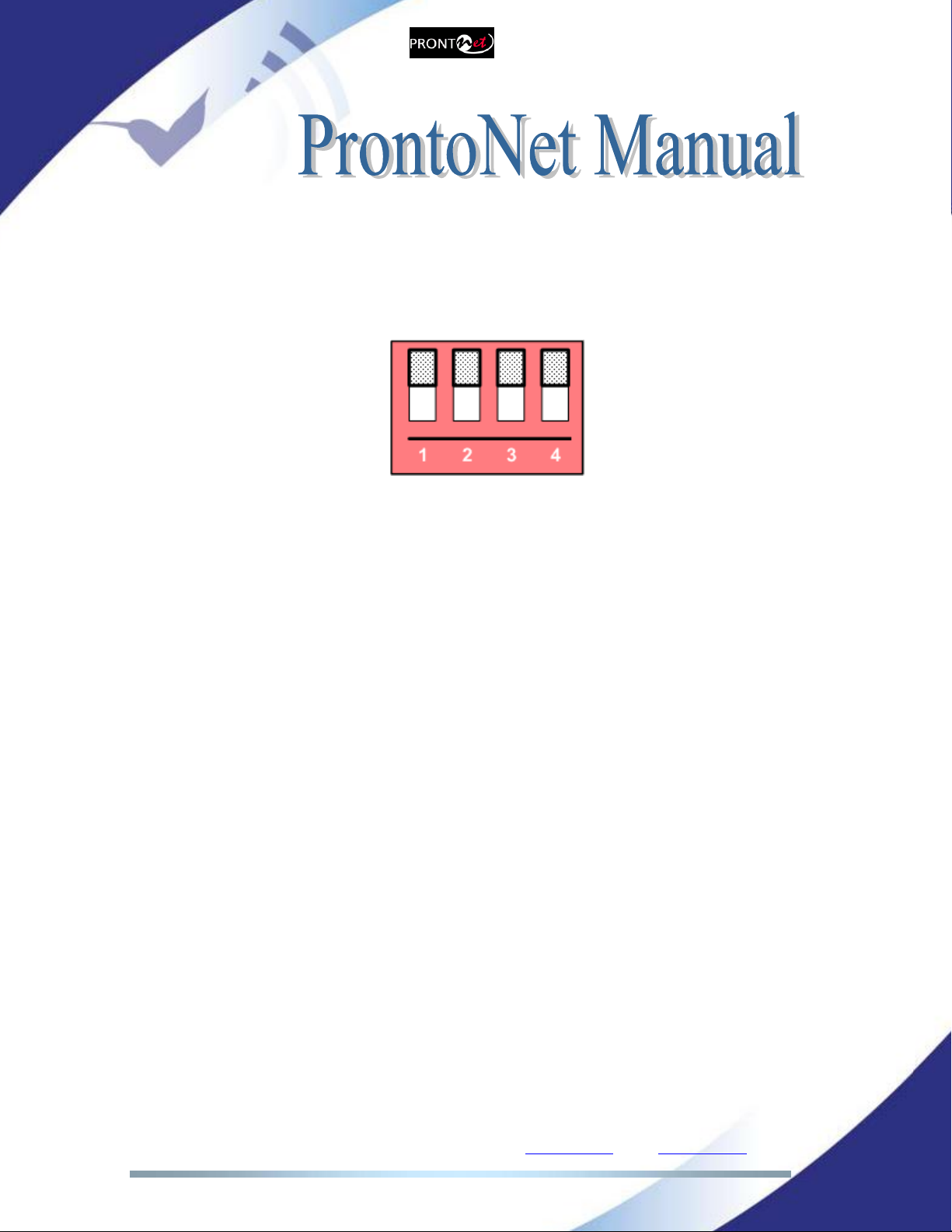
II.3.6 Microswitches
There are 4 microswitches on the back panel which are reserved for special
functions. Before turning on the unit the user must check that they are
configured according to the following diagram, which is the standard start-up
configuration:
Switch number 3 will restore the default factory configuration. The IP address
will be changed to 192.168.100.100 and the netmask to 255.255.255.0.
Prodys S.L. Tel: +34 91 6896880 Fax: +34 91 6943777 Email: sales@prodys.net Web: www.prodys.com
Page 19
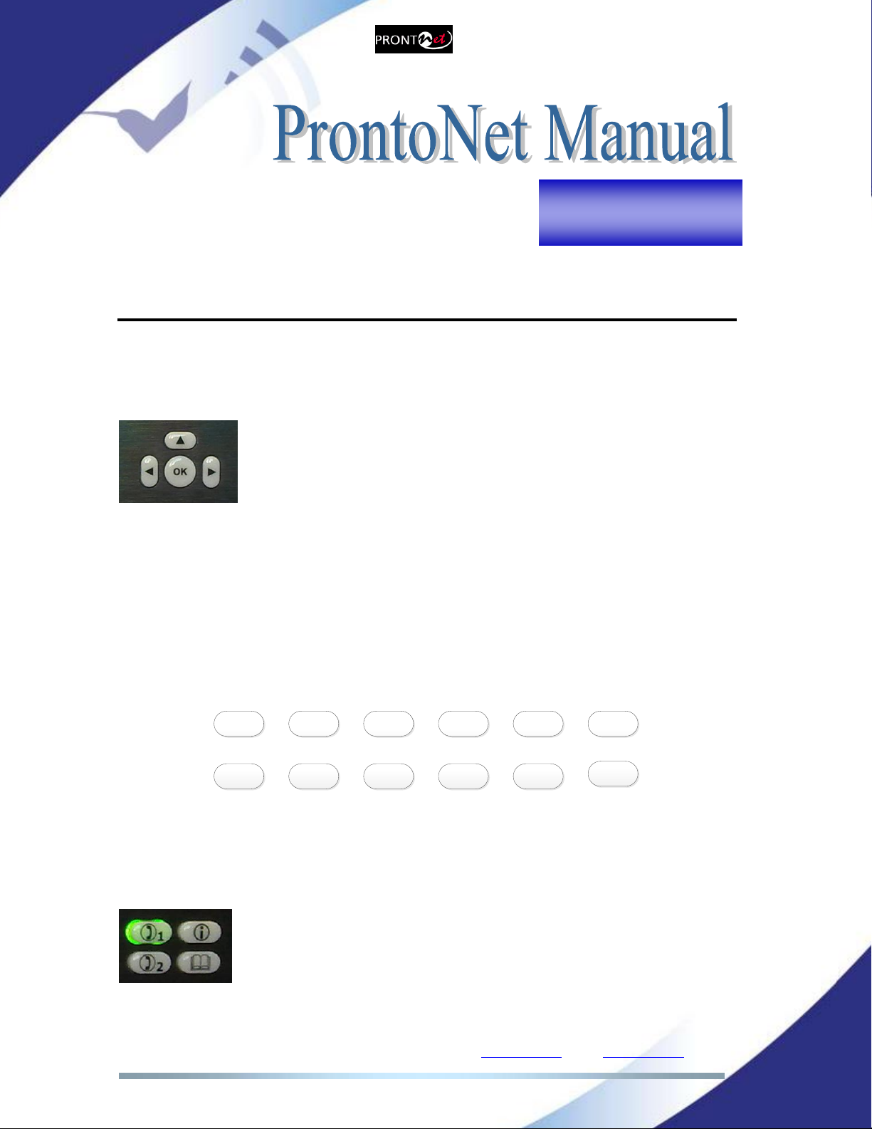
AN INTRODUCTION TO THE FRONT PANEL
The front panel of the ProntoNet has a display and keypads that allow you to
control and configure the unit. The keys are laid out in the following manner:
Navigation Keys: The keys , , , are used for moving
around the menus and the <OK> is for selecting/accepting the
desired action or parameter.
Alphanumeric keypad: This keypad is used to enter information such as the IP
address or ISDN number that you wish to connect to. From firmware version
6.5.8 onwards, it is also possible to both edit phone book entries and make calls
to destination addresses containing alphanumeric characters.
Even though the hardware of your current Prodys codec does not come equipped
with an alphanumeric labelled keypad, this new firmware supports the following
keypad layout:
2abc 3def 4ghi 5jkl *.1@
7pqrs 8tuv 9wxyz 0+ #:
6mno
The operation is just like in a regular mobile phone, just press several times the
same key in order to get the different characters.
CONTROL Keys: There are several special keys grouped together:
<CALL1> and <CALL2> are for establishing and terminating
connections, and also to monitor the called/calling number.
<i> is for viewing status information.
<BOOK> for establishing communications using a
configuration saved in the Address Book.
Chapter III

Prodys S.L. Tel: +34 91 6896880 Fax: +34 91 6943777 Email: sales@prodys.net Web: www.prodys.com
Page 20
L 1 : I D L E ( 0 ) I S D N
L 2 : I D L E ( 0 ) B K U P O N
III.1 Display
To help explain the ProntoNet DISPLAY we should distinguish between the status
screen and the menu screen:
The status screen shows information about the communication lines and
the status of the Decoder.
The Menu screen shows the different configuration menu options and is
only displayed when you press OK on the navigation menu keys.
III.1.1 STATUS SCREEN
This is the default screen that you will see when the ProntoNet is ‘at rest’, that is,
when you are not navigating or using the front panel keys. It reports the status
of the communications and the Decoder.
More information about this in the following sections.
The display will show information in the following way:
The first line shows information about the status of communication Line 1,
followed by status information of the audio Decoder.
The second line shows information about the status of communication Line 2.
(This line will only be enabled when working as a DUAL codec4) .
The communication lines will be in one of the following states:
DOWN:The communication line is not physically detected. Most likely the
interface is not plugged in. The Display shows “DOWN”:
4DUAL codec: ProntoNet is able to operate as a DUAL codec over ISDN and over IP (when
configured in ‘DOUBLE’ mode).
L1C O N N E C T E D F R A M E D
L 2 : I D L E
L1:DOWN ISDN
L2:DOWN
Status
Line 1
Status
Decoder 1
Backup
status
Other manuals for ProntoNet
3
Table of contents
Other Prodys Recording Equipment manuals


