Professional Entertainment Technology StairVille MH-360 User manual


- 2 -
Congratulations on your purchase of this Moving Head.
To get the most from your equipment you must read all of this
manual before using it rst time.
Table of Contents
1. Safety Instruction .......................................................................... 3
Warning ....................................................................................... 3
Caution ........................................................................................ 4
Installation ................................................................................... 4
2. Technical Specification ................................................................... 4
2.1 Change Beam Angle ............................................................. 5
3. How To Set The Unit ..................................................................... 5
3.1 Control Panel ......................................................................... 5
3.2 Main Function ......................................................................6
3.3 Home Position Adjust ......................................................... 11
4. How To Control The Unit ........................................................... 11
4.2 POCKET-MASTER I .............................................................. 12
4.3 Universal DMX Controller .................................................... 12
4.4 DMX 512 Configuration ....................................................... 13
4.5 DMX512 Connection .......................................................... 14
5. Troubleshooting .......................................................................... 15
6. Fixture Cleaning .......................................................................... 16
7. Disposal ...................................................................................... 16

- 3 -
1. Safety Instruction
You have to carefully read the instruction, which includes
important information about the installation, usage and
maintenance.
• Please keep this User Guide for future consultation. If you sell
the unit to another user, be sure that they also receive this in-
struction booklet.
• Unpack and check carefully there is no transportation damage
before using the unit.
• Before operating, ensure that the voltage and frequency of power
supply match the power requirements of the unit.
• It’s important to ground the yellow/green conductor to earth in
order to avoid electric shock.
• The unit is for indoor use only. Use only in a dry location.
• The unit must be installed in a location with adequate ventila-
tion, at least 50cm from adjacent surfaces. Be sure that no ven-
tilation slots are blocked.
• Disconnect main power before replacement or servicing.
• Make sure there is no ammable materials close to the unit
while operating as it is re hazard.
• Use safety cable when xes this unit. Don’t handle the unit by
taking its head only, but always by taking its base.
• Maximum ambient temperature is TA: 40°C. Don’t operate it
where the temperature is higher than this.
• Unit surface temperature may reach up to 85°C. Don’t touch the
housing bare-hand during its operation. Turn off the power and
allow about 15 minutes for the unit to cool down before replac-
ing or serving.
• In the event of serious operating problem, stop using the unit
immediately. Never try to repair the unit by yourself. Repairs
carried out by unskilled people can lead to damage or malfunc-
tion. Please contact the nearest authorized technical assistance
center. Always use the same type spare parts.
• Do not touch any wire during operation as high voltage might be
causing electric shock.
Warning
• To prevent or reduce the risk of electrical shock or re, do not
expose the unit to rain or moisture.

- 4 -
• Do not open the unit within ve minutes after switching off.
• The housing, the lenses, or the ultraviolet lter must be replaced
if they are visibly damaged.
Caution
There are no user serviceable parts inside the unit. Do not open
the housing or attempt any repairs by yourself. In the unlikely
event your unit may require service, please contact your nearest
dealer.
Installation
The unit should be mounted via its screw holes on the bracket. Al-
ways ensure that the unit is rmly xed to avoid vibration and slip-
ping while operating. Always ensure that the structure to which you
are attaching the unit is secure and is able to support a 10 times
weight of the unit.
2. Technical Specification
• Voltage: AC 230V 50Hz
• The unit is DMX 512 xture. It features full DMX 512 control. It
can be also linked together in master/slave connection, as many
as required and run by built-in program chase sequences auto-
matically or by sound activation through an internal microphone
to create an intelligent effect.
• It can be operated by DMX 512 control or can be used as an in-
dividual unit without a controller.
• Features different preprogrammed chase patterns.
• Please use a cable when connecting units together.
• Accurate focusable optics system and ultra smooth stepping mo-
tors, Fan cooled.
• Pan: 540 deg.
Tilt: 220 deg.
• Dimension:
260x 285 x 317 mm
• Weight: 9.0 kg

- 5 -
2.1 Change Beam Angle
In this CM series, if you want to change the beam angle of xture,
you can change lens of the xture as below:
3. How To Set The Unit
3.1 Control Panel
Display
To show the various menus and the selected functions
LED
DMX On DMX input present
MASTER On Master Mode
SLAVE On Slave Mode
SOUND Flashing Sound activation
angle art.-no.
15° 219955
25° 219957 (standard)
45° 219956

- 6 -
Button
MENU To select the programming functions
DOWN To go backward in the selected functions
UP To go forward in the selected functions
ENTER To conrm the selected functions
Mainsinput
IEC socket and integrated fuse holder, connect to main power ca-
ble.
Onlyforremotecontrol
By connect to the 1/4’’ microphone jack to control the unit for
Stand by, Function and Mode function.
Sensitivity
To adjust the sound receiving sensitivity
DMXinput/output
For DMX512 link, use 3-pin XLR plug cable to link the unit togeth-
er.
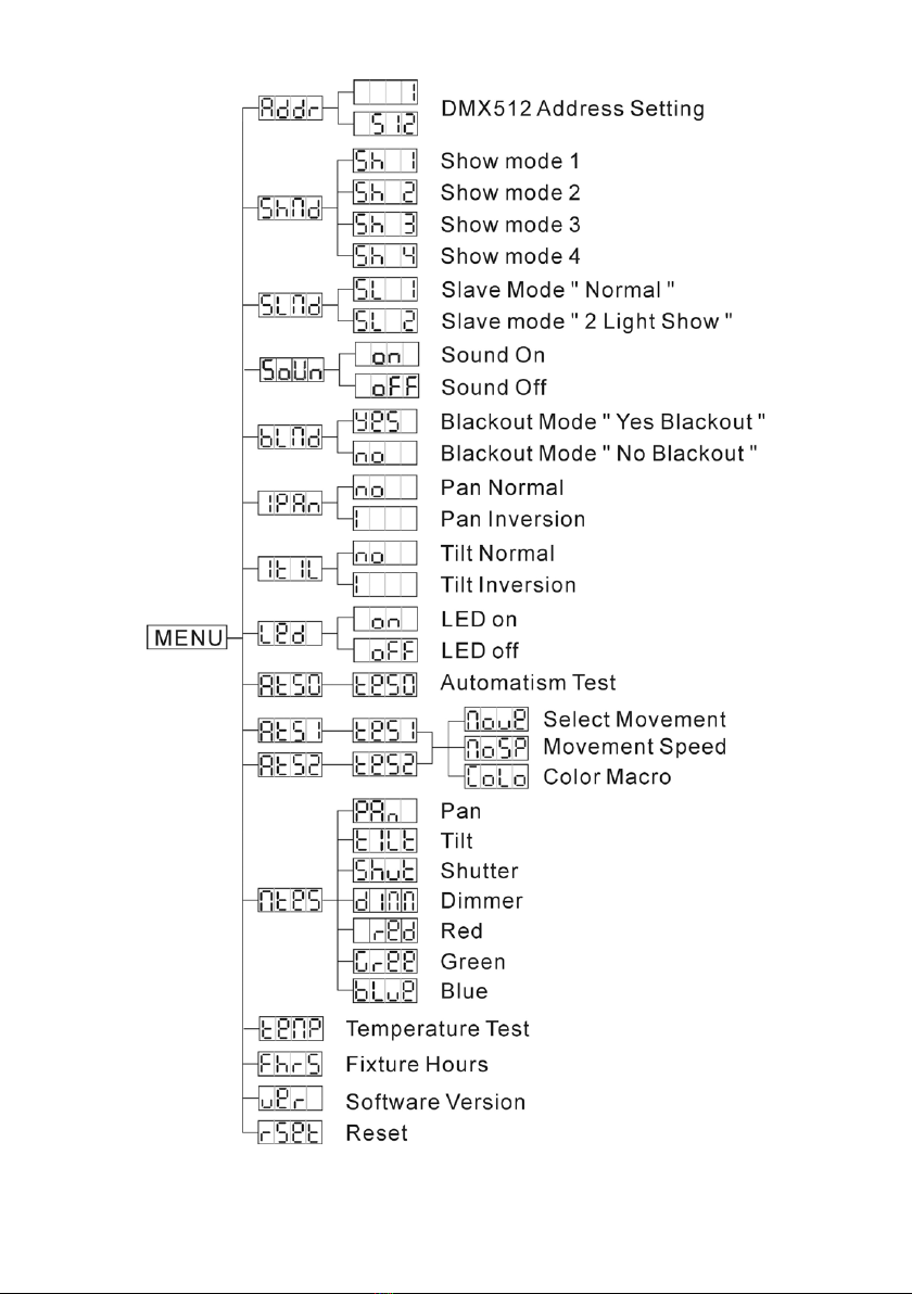
3.2 Main Function
To select any of the given functions, press the MENU button up to
when the required one is showing on the display. Select the func-
tion by ENTER button and the display will blink. Use DOWN and
UP button to change the mode. Once the required mode has been
selected, press the ENTER button to setup or it will automatically
return to the main functions without any change after idling 8
seconds. To go back to the functions without any change press the
MENU button. The main functions are showing below:
- 7 -
- 8 -
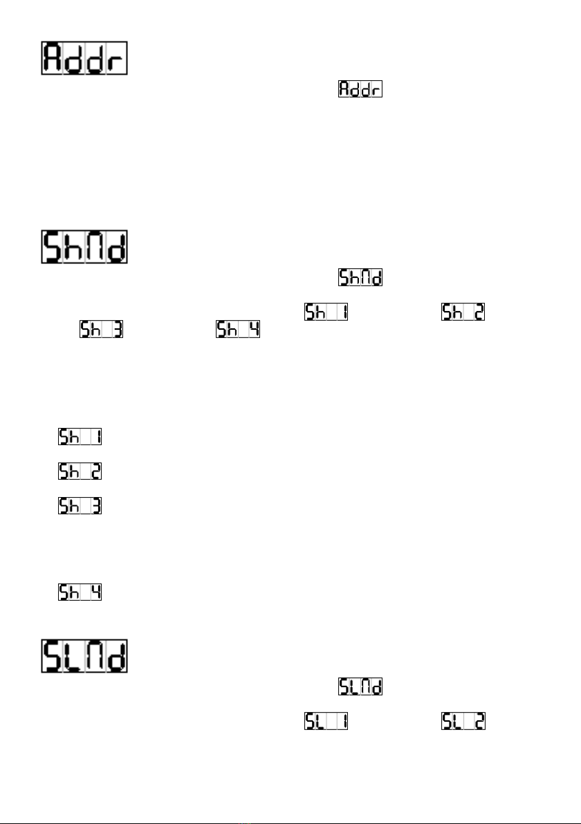
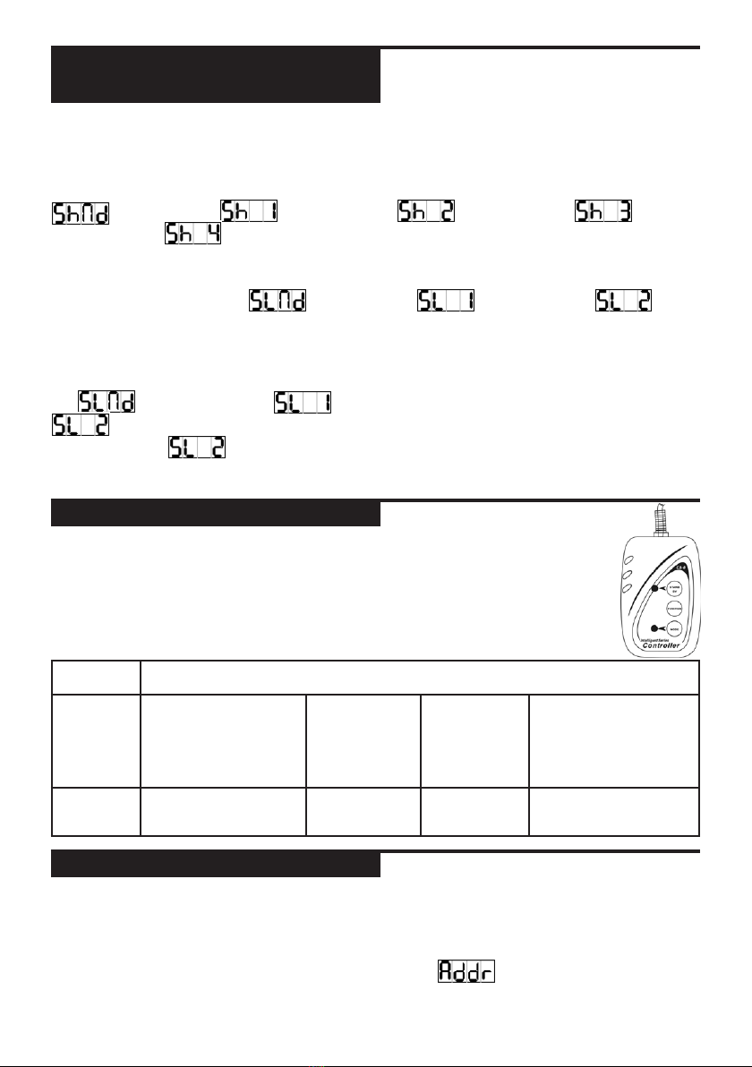
DMX 512 Address Setting
Press the MENU button up to when the is showing on the
display. Pressing ENTER button and the display will blink. Use
DOWN and UP button to change the DMX512 address. Once the
address has been selected, press the ENTER button to setup or au-
tomatically return to the main functions without any change after
8 seconds. To go back to the functions without any change press
the MENU button again.
Show Mode
Press the MENU button up to when the is showing on the
display. Pressing ENTER button and the display will blink. Use
DOWN and UP button to select the (show 1) or (show
2) or (show 3) or (show 4) mode. Once the mode has
been selected, press the ENTER button to setup or automatically
return to the main functions without any change after 8 seconds.
To go back to the functions without any change press the MENU
button again.
Show 1 mode - Fixture is placed on the oor. Tilt
movement angle 210°.
Show 2 mode - Fixture is xed under ceiling. Tilt
movement angle 90°.
Show 3 mode - Fixture is placed on the speaker, The
spot is always projecting to the audience’s direction;
i.e in front of the stage. Pan movement angel (left to
right to left): 160°. Tilt movement angel: 90° (60°
above horizon; 30° below horizon.)
Show 4 mode - Fixture is xed under ceiling. The spot
is mainly projecting in front of the stage. Pan
movement angel (left to right to left):160°. Tilt
movement angel: 90° (vertically, front 75°; back 15°)
Slave Mode
Press the MENU button up to when the is showing on the
display. Pressing ENTER button and the display will blink. Use
DOWN and UP button to select the (normal) or (2
light show) mode. Once the mode has been selected, press the EN-
TER button to setup or automatically return to the main functions
without any change after 8 seconds. To go back to the functions
- 9 -
without any change press the MENU button again.
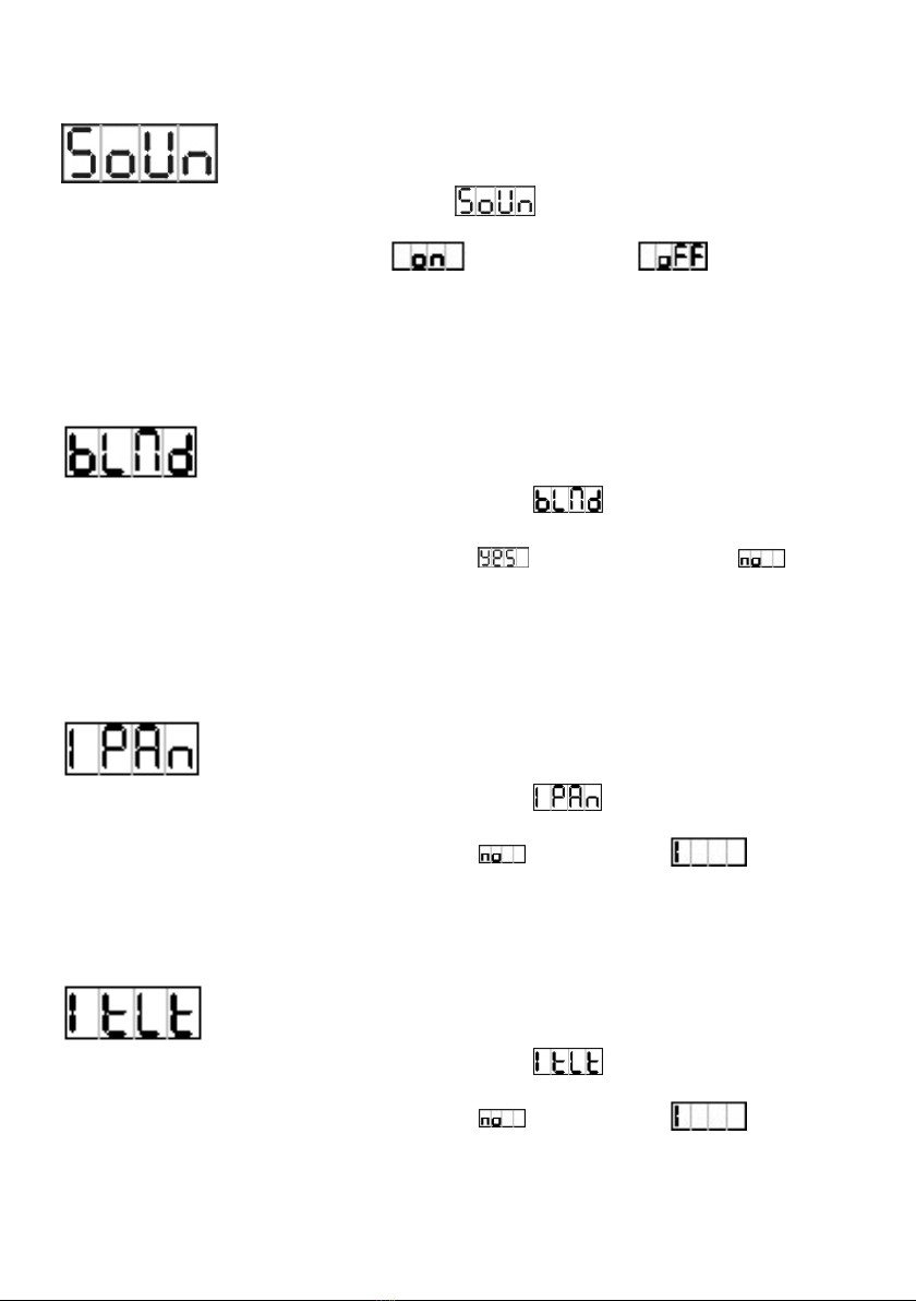
Sound Mode
Press the MENU button until the is showing on the display.
Pressing ENTER button and the display will blink. Use DOWN
and UP button to select the (sound on) or (sound off)
mode. Once the mode has been selected, press the ENTER button
to setup or automatically return to the main functions without any
change after 8 seconds. To go back to the functions without any
change press the MENU button again.
Blackout Mode
Press the MENU button up to when the is showing on the
display. Pressing ENTER button and the display will blink. Use
DOWN and UP button to select the (yes blackout) or (no
blackout) mode. Once the mode has been selected, press the EN-
TER button to setup or automatically return to the main functions
without any change after 8 seconds. To go back to the functions
without any change press the MENU button again.
Pan Inversion
Press the MENU button up to when the is showing on the
display. Pressing ENTER button and the display will blink. Use
DOWN and UP button to select the (normal) or (pan
inversion) mode. Once the mode has been selected, press the EN-
TER button to setup or automatically return to the main functions
without any change after 8 seconds. To go back to the functions
without any change press the MENU button again.
Tilt Inversion
Press the MENU button up to when the is showing on the
display. Pressing ENTER button and the display will blink. Use
DOWN and UP button to select the (normal) or (tilt
inversion) mode. Once the mode has been selected, press the EN-
TER button to setup or automatically return to the main functions
without any change after 8 seconds. To go back to the functions
without any change press the MENU button again.
- 10 -
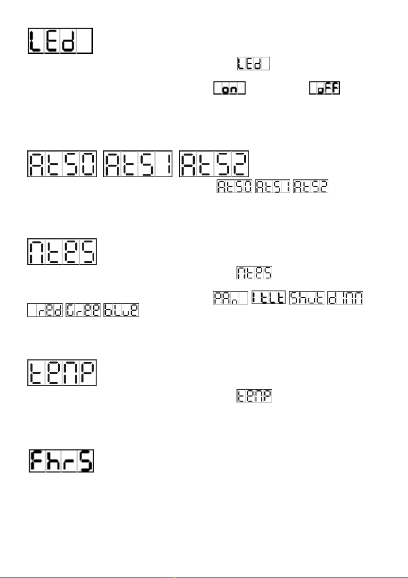
Led Display
Press the MENU button up to when the is showing on the
display. Pressing ENTER button and the display will blink. Use
DOWN and UP button to select the (Led on) or (Led
off) mode. Once the mode has been selected, press the ENTER but-
ton to setup or automatically return to the main functions without
any change after 8 seconds. To go back to the functions without
any change press the MENU button again.
Test
Press MENU button up to when the is show
on the display. Pressing ENTER button and the unit will run Self
test by built in program and can test by program. Back to the
functions press MENU button again.
Master Mode
Press the MENU button up to when the is showing on the
display. Pressing ENTER button and the display will blink. Use
DOWN and UP button to select the
. Once the mode has been selected, press the
ENTER button to setup or automatically return to the main func-
tions without any change after 8 seconds. To go back to the func-
tions without any change press the MENU button again.
Temperature Test
Press the MENU button up to when the is blinking on the
display. Pressing ENTER button and the display will show the tem-
perature of the unit. To go back to the functions press the MENU
button.
Fixture Hours
Press the MENU button up to when the is blinking on the display.
Pressing ENTER button and the display will show the number of
working hours of the unit. To go back to the functions press the
MENU button again.

- 11 -
Software version
Press the MENU button up to when the is blinking on the display.
Pressing ENTER button and the display will show the version of
software of the unit. To go back to the functions press the MENU
button again.
Reset
Press the MENU button up to when the is blinking on the display.
Pressing ENTER button and all channels of the unit will return to
their standard position. To go back to the functions without any
change press the MENU button again.
3.3 Home Position Adjust
Press Enter button for at least 5 seconds into offset mode to ad-
just the home position, use DOWN and UP button up to function
(Pan, Tilt, B-red, B-green, B-blue) is shown on the display. Press-
ing ENTER button and the display will blink. Use DOWN and UP
button to adjust the home position. Once the position has been
selected, press the ENTER button to setup or automatically return
to the offset functions without any change press the MENU button
again, To go back to the main functions without any change after 8
seconds.
4. How To Control The Unit
You can operate the unit in three ways:
1. By master/slave built-in preprogram function
2. By pocket-master I
3. By universal DMX controller
No need to turn the unit off when you change the DMX address, as
new DMX address setting will be effected at once. Every time you
turn the unit on, it will move all the motors to their ‘home’ position
and you may hear some noises for about 20 seconds. After that the
unit will be ready to receive DMX signal or run the built in pro-
grams.
- 12 -
4.1 Master/Slave Built In
Preprogrammed Function
By linking the units in master/slave connection, the rst unit
will control the other units to give an automatic, sound activated,
synchronized light show. This function is good when you want an
instant show. You have to set the rst unit in master mode
and select (show 1) or (show 2) or
(show 3) or (show 4) mode. Its DMX input jack will have
nothing plugged into it, and Its master LED will be constantly on
and sound LED will ash to the music. The other units will have
to set in slave mode and select (normal) or (2
light show) mode, their DMX cables plugged into the DMX input
jacks (daisy chain) and the slave led lights will constantly on.
2-lightshow
In (slave mode), means the unit works normally and
means 2-light show. In order to create a great light show,
you can set on the second unit to get contrast movement to
each other, even if you have two units only.
4.2 POCKET-MASTER I
The easy remote control is used only in master/slave
mode. By connecting to the 1/4” microphone jack of
the rst unit, you will nd that the remote control on
the rst unit will control all the other units functions
press the MENU button again.
Stand By Blackout the unit
Function 1. Sync. Strobe
2. Two-light strobe
3. Sound Strobe
Select Show
1-4
Fade Speed
Fast
Middle
Slow
1. Pan Positioning
2. Tilt Positioning
3. Dimmer or Color
change
Mode Sound (LED OFF) LED Normal
Blinking
LED ON LED fast Blinking
4.3 Universal DMX Controller
An universal DMX controller to control the units, you have to set
DMX address from 1 to 512 channel so that the units can receive
DMX signal.
Press the MENU button up to when the is showing on the
display. Pressing ENTER button and the display will blink. Use
- 13 -
DOWN and UP button to change the DMX512 address. Once the
address has been selected, press and keep ENTER button pressed
up to when the display stops blinking or storing automatically
8 seconds later. To go back to the functions without any change
press the MENU button again. If you use please refer to the follow-
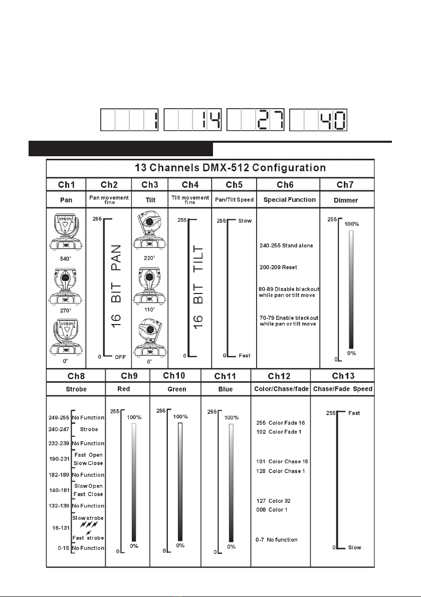
ing diagram to address your DMX512 channel for the rst 4 units.
13 channels
4.4 DMX 512 Configuration

- 14 -
4.5 DMX512 Connection
The DMX 512 is widely used in intelligent lighting control, with a
maximum of 512 channels.
1. If you using a controller with 5 pins DMX output, you need to
use a 5 to 3 pin adapter-cable.
2. At last unit, the DMX cable has to be terminated with a termi-
nator. Solder a 120 ohm 1/4W resistor between pin 2(DMX-)
and pin 3(DMX+) into a 3-pin XLR-plug and plug it in the
DMX-output of the last unit.
3. Connect the unit together in a `daisy chain` by XLR plug from
the output of the unit to the input of the next unit. The cable
can not branched or split to a `Y` cable. DMX 512 is a very
high-speed signal. Inadequate or damaged cables, soldered
joints or corroded connectors can easily distort the signal and
shut down the system.
4. The DMX output and input connectors are pass-through to
maintain the DMX circuit, when power is disconnected to the
unit.
5. Each lighting unit needs to have an address set to receive the
data sent by the controller. The address number is between

- 15 -
0-511 (usually 0 & 1 are equal to 1).
6. The end of the DMX 512 system should be terminated to re-
duce signal errors.
7. 3 pin XLR connectors are more popular than 5 pin XLR.
3 pin XLR: Pin 1: GND, Pin 2: Negative signal (-), Pin 3: Positive
signal (+)
5 pin XLR: Pin 1: GND, Pin 2: Negative signal (-), Pin 3: Positive
signal (+)
5. Troubleshooting
Following are a few common problems that may occur during op-
eration. Here are some suggestions for easy troubleshooting:
A.Theunitdoesnotwork,nolightandthefandoesnotwork
1. Check the connect power and main fuse.
2. Check the mains outlet for proper functioning.
3. Check the power on LED.
B.NotrespondingtoDMXcontroller
1. DMX LED should be on. If not, check DMX connectors, cables
to see if link properly.
2. If the DMX LED is on and no response to the channel, check
the address settings and DMX polarity.
3. If you have intermittent DMX signal problems, check the pins
on connectors or on PCB of the unit or the previous one.
4. Try to use another DMX controller.
5. Check if the DMX cables run near or run alongside to high
voltage cables that may cause damage or interference to DMX
interface circuit.
C.Someunitsdon’trespondtothepocket-masterI
1. You may have a break in the DMX cabling. Check the LED for
the response of the master/ slave mode signal.
2. Wrong DMX address in the unit. Set the proper address.
D.Noresponsetothesound
1. Make sure the unit is not receiving DMX signal.
2. Check microphone to see if it is good by tapping the micro-
phone.

- 16 -
E.Oneofthechannelsisnotworkingwell
1. The stepper motor might be damaged or the cable connected to
the PCB is broken. Consult your dealer then.
2. The motor’s drive IC on the PCB might be out of condition.
Consult your dealer then.
F.IfThepanbeltisbroken...
. . . consult your dealer.
6. Fixture Cleaning
The cleaning of the head lens must be carried out periodically to
keep the light output optimum. Cleaning frequency depends on the
environment in which the xture operates: damp, smoky or par-
ticularly dirty surrounding can cause greater accumulation of dirt
on the unit’s lens.
• Clean with soft cloth using normal glass cleaning uid.
• Always dry the parts carefully.
• Clean the head lens at least every 20 days.
7. Disposal
Donotdisposeofthedeviceattheendofhisoperat-
inglifeinyournormaldomesticwaste.Thisdeviceis
subjecttotheEuropeanGuidelines2002/96/EC.
• Have the product disposed of by a professional disposal compa-
ny of by your communal disposal facility.
• Observe the currently applicable regulations. In case of doubt
contact your disposal facility.
• Dispose of packaging materials in an environmentally
responsible manner.

- 17 -
ECDeclarationofConformity
We declare that our products (lighting equipments) comply with
the following specication and bears CE mark in accordance with
the provision of the Electromagnetic Compatibility (EMC) Directive
89/336/EEC.
EN55014-2: 1997 A1:2001, EN61000-4-2: 1995;
EN61000-4-3:2002;
EN61000-4-4: 1995; EN61000-4-5: 1995, EN61000-4-6:1996,
EN61000-4-11: 1994.
&
HarmonizedStandard
EN 60598-1: 2000 +ALL: 2000+A12: 2002
Safety of household and similar electrical appliances, Part 1: Gen-
eral requirements.

- 18 -

- 19 -

Contact:
Musikhaus Thomann e.K.
Treppendorf 30
96138 Burgebrach
Germany
www.thomann.de
Table of contents
Popular Light Fixture manuals by other brands


Wolf
Wolf WOLFLITE H-251 Operation & maintenance instructions

Intermatic
Intermatic WL250HPS installation instructions

Lightolier
Lightolier QVS2GPFOB232 Installation

Masco
Masco IR50 spot operating instructions

Cooper Lighting Solutions
Cooper Lighting Solutions Lumark AP installation instructions

Boca Flasher
Boca Flasher HPNFC-RT installation manual


