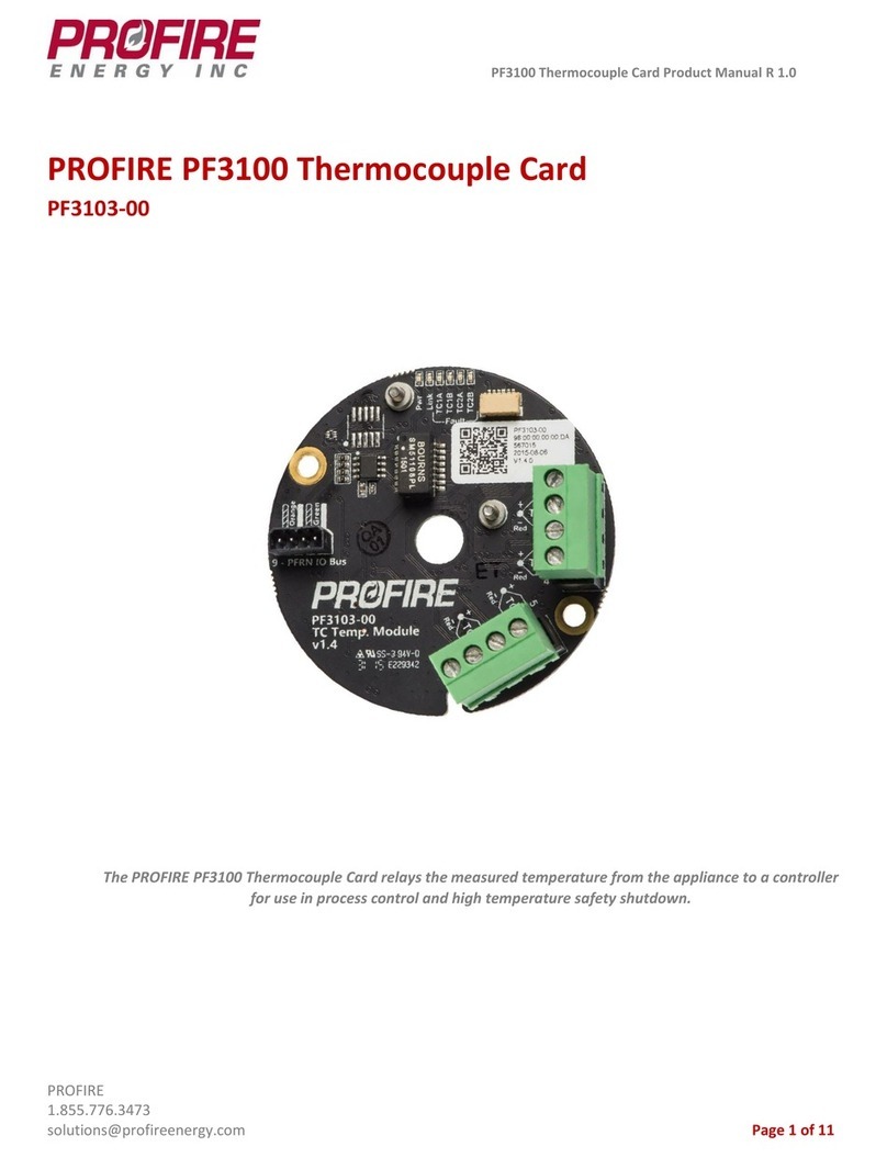
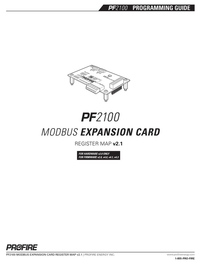
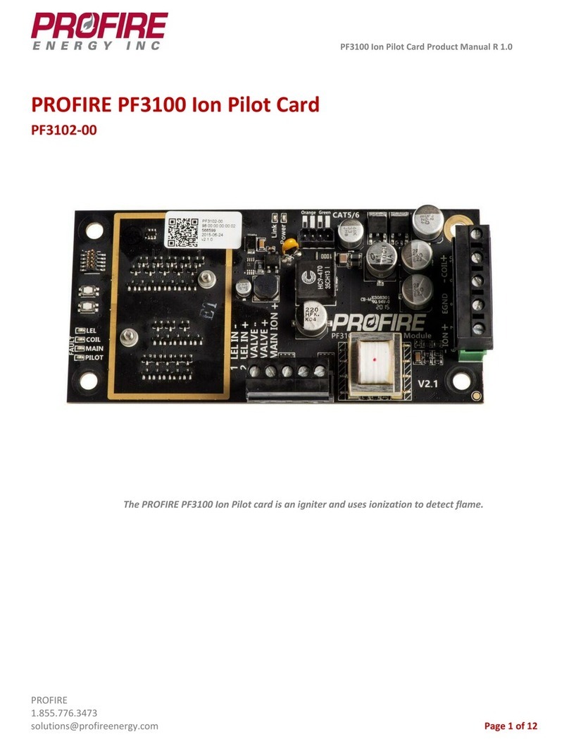
ProFire PF3100 Series User manual

PF3100 Modbus Card Product Manual R 1.0
PROFIRE
1.855.776.3473
solutions@profireenergy.com Page 1 of 10
PROFIRE PF3100 Modbus Card
PF3107-00
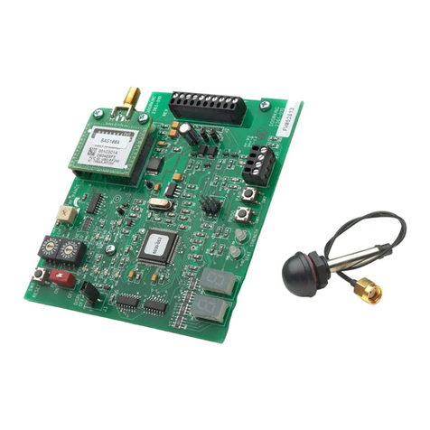
The PROFIRE PF3100 IO Modbus RS-485 card allows a PF3100 system to interact with other devices.

PF3100 IO Modbus Card Product Manual
PROFIRE
1.855.776.3473
solutions@profireenergy.com Page 2 of 10
1. Introduction............................................................................................................................................... 3
2. Certifications..............................................................................................................................................3
3. Card Information........................................................................................................................................4
4. Wiring Diagram .......................................................................................................................................... 6
5. Mounting Instructions ................................................................................................................................7
6. Enclosure Specifications ............................................................................................................................. 8
7. Instructions for Use .................................................................................................................................... 8
8. Preventative Maintenance & Inspection .....................................................................................................8
9. Important Safety Information.....................................................................................................................9
10. PROFIRE Contact Information ................................................................................................................... 10

PF3100 IO Modbus Card Product Manual
PROFIRE
1.855.776.3473
solutions@profireenergy.com Page 3 of 10
1. Introduction
Functional Description
The PROFIRE PF3100 Modbus RS-485 card allows the PF3100 system to interact with other devices, such as PLCs
and SCADA networks that support RS-485 two wire (half-duplex) communication via Modbus RTU Protocol. This
card is always a Modbus slave device. Separate Modbus master devices can start/stop the system, read system
status and process values, and modify settings.
Model Types
Model Number
Name
Description
PF3107-00A
Modbus TCP and Modbus RTU
Standalone - polyester painted steel enclosure.
2. Certifications
PROFIRE strives to ensure that certifications are updated as quickly as they become available for all of our products.
Modbus Card - Hazardous Location Rating
Certification: Class I, Div 2, Grp ABCD; T4; Type 4
CSA 22.2 No. 60730-2-5, UL 60730-2-5.
The board includes the following symbols:
Caution: possibility of electric shock.
Caution: documentation must be consulted in all cases where this symbol is marked.

PF3100 IO Modbus Card Product Manual
PROFIRE
1.855.776.3473
solutions@profireenergy.com Page 4 of 10
3. Card Information
Card Specifications
The ambient temperature rating for the Modbus Card is -40°C (-40°F) to +60°C (+140°F).
Card Diagram

PF3100 IO Modbus Card Product Manual
PROFIRE
1.855.776.3473
solutions@profireenergy.com Page 5 of 10
Terminal Specifications
Terminal
Number
Terminal Name
Expected Connections
Input/Output
Safety
Rated
Electrical Ratings
Voltage
Current
1
Power 12-24 VDC
Vin -
Input power from a DC source
12/24 VDC Power
Input
N/A
Nominal:
12 VDC or
24 VDC
Max: 30V
Max: 6A
2
Common 12-24
VDC Vin +
Ground back to DC source
Ground
N/A
N/A
N/A
3
EGND
Earth Ground
Ground
N/A
N/A
N/A
6 + 7
Status Out
Not implemented.
Not
implemented.
No
120VAC
50/60Hz or
12/24 VDC
80mA
4
Start Signal In
Not implemented.
Not
implemented.
No
30 VDC
5mA
5
Start PWR Out
Not implemented.
Not
implemented.
No
12 VDC or
24VDC
(same as
voltage
supply
150mA
8
RS-485 D+
Connect to a RS-485 Bus
connected to a PLC or similar
device.
RS-485
Input/Ouput
No
+/-6V
250mA
9
RS-485 D-
Connect to a RS-485 Bus
connected to a PLC or similar
device.
RS-485
Input/Ouput
No
+/-6V
250mA
10
RS-485 Reference
(Terminal 10)
Connect to a RS-485 Bus
connected to a PLC or similar
device.
Ground
N/A
N/A
N/A
Port
Number
Port Name
Expected Connections
Input/Output
Safety
Rated
Electrical Ratings
Voltage
Current
1
PFRN Port 1
The PFRN IO connect ports are
used for IO modules to
communicate with the BMS
card.
I/O
N/A
36 VDC
500mA
2
PFRN Port 2
The PFRN IO connect ports are
used for IO modules to
communicate with the BMS
card.
I/O
N/A
3
PFRN Port 3
The PFRN IO connect ports are
used for IO modules to
communicate with the BMS
card.
I/O
N/A
4
PFRN Port 4
The PFRN IO connect ports are
used for IO modules to
communicate with the BMS
card.
I/O
N/A

PF3100 IO Modbus Card Product Manual
PROFIRE
1.855.776.3473
solutions@profireenergy.com Page 6 of 10
Terminal Descriptions
Power, Common
Input power 12/24 VDC, 6.3A max.
EGND
Internally connected to Common; must be wired to a nearby Earth Ground.
RS-485 D+/D-
-7V to 12V absolute.
+/- 3VDC differential recommended.
The baud rates supported are from 9600 baud to 19200.
RS-485 Reference (Terminal 10)
Shared common ground with customer PLC. Must be wired in.
Terminator Selector Switch
The termination selector switch is used to apply a 120ohm resistance to the signal. By applying this resistance,
it in turn “terminates” the signal. It should only be used when you want to terminate the signal.
4. Wiring Diagram

PF3100 IO Modbus Card Product Manual
PROFIRE
1.855.776.3473
solutions@profireenergy.com Page 7 of 10
Wiring Specifications
12-30 AWG can be used for all connections. External fuses must be installed according to the local electrical code.
Wire gauge size must also be selected in accordance with local electrical codes.
5. Mounting Instructions
Mounting the Card in the Enclosure
1. Install four (4) #10-32 screws through the Modbus card (as indicated in the image below) and attach them to
the upper set of enclosure stand-offs. Please note the board orientation.
2. Torque to 26 in*lb.

PF3100 IO Modbus Card Product Manual
PROFIRE
1.855.776.3473
solutions@profireenergy.com Page 8 of 10
6. Enclosure Specifications
The Modbus card can be mounted in a fire-proof enclosure that is safe for the area of operation (e.g. –
hazardous/non-hazardous.) The UIX, CTX, and AUX enclosures described below are examples:
Enclosure Type
Specifications
UIX
CTX
AUX
Dimensions
Height 30.9cm (12.15 inches)
Width 23.4cm (9.23 inches)
Depth 13.4cm (5.28 inches)
Height 30.9cm (12.15 inches)
Width 23.4cm (9.23 inches)
Depth 13.4cm (5.28 inches)
Height 30.9cm (12.15 inches)
Width 23.4cm (9.23 inches)
Depth 13.4cm (5.28 inches)
Hazloc Rating
Class I Div 2, IP66
Class I Div 2, IP66
Class I Div 2, IP66
Mounting
Channel Bar or Direct Mount
Channel Bar or Direct Mount
Channel Bar or Direct Mount
Enclosure Construction
Poly Painted Steel
Poly Painted Steel
Poly Painted Steel
Operating Temperature
-40°C (-40°F) to 60°C (140°F)
-40°C (-40°F) to 60°C (140°F)
-40°C (-40°F) to 60°C (140°F)
Storage Temperature
-40°C (-40°F) to 60°C (140°F)
-40°C (-40°F) to 60°C (140°F)
-40°C (-40°F) to 60°C (140°F)
7. Instructions for Use
The Modbus card is designed to be used with a certified BMS controller as part of the PF3100 platform.
Operation
Operating controls and their uses are described under “Terminal Descriptions” above. For an outline of all registers
supported through Modbus, please see the link below for the document “Modbus Register Map”:
http://3100.profireenergy.com/pf3100-documentation/
8. Preventative Maintenance & Inspection
In order to ensure that the Modbus card works correctly and efficiently, the following maintenance and inspection
procedures should be followed:
➢Ensure that all wires are connected correctly.
➢Minimize copper wire exposure.
➢Check for corrosion and ensure that no wires are frayed or worn out, and all insulation is intact.
➢Confirm no moisture or condensation is apparent on the board or in the enclosure.
➢Ensure that the board does not show any sign of mechanical damage (e.g. –damage from an impact such as
dropping an item).
➢Ensure that the board does not show any sign of electrical damage (components should not be burnt or
damaged in any way).
➢Check that the device is not subject to excessive vibration.
➢Confirm that the temperature of the board is within ambient temperature operating limits.
➢Check that the enclosure is secured and that the device is not subject to excessive vibration.
➢Routine inspections of all equipment should be performed. If any abnormality is found, corrective actions should
be taken. If the abnormality cannot be corrected, contact PROFIRE.

PF3100 IO Modbus Card Product Manual
PROFIRE
1.855.776.3473
solutions@profireenergy.com Page 9 of 10
➢A qualified technician should perform any tests necessary to confirm that the equipment is still in a safe
condition.
Cleaning
If the card becomes dirty it can be cleaned with compressed air. Do NOT use solvents, cleaners, or liquids to clean
the board. Caution must be exercised when cleaning the board in order to prevent damage from ESD (electrostatic
discharge).
Replacement Parts
Please contact PROFIRE should any replacement parts be required.
9. Important Safety Information
Before installing the PF3100 Modbus card, please review the list of warnings below. Product use in a manner not
specified by PROFIRE is not recommended. Failure to observe the following warnings may result in death,
electrocution, property damage, product damage, product damage, government fines, or malfunction of the
product itself.
WARNING: Explosion Hazard
➢Do not disconnect while circuit is live unless area is known to be non-hazardous or equivalent.
➢Substitution of components may impair suitability for specified zones.
➢Do not service unless the area is known to be non-hazardous.
➢Do not open when energized.
➢Installation and use must conform to the directions in this guide.
➢System must be properly connected to earth-ground for effective operation of flame detection circuitry.
Installation Warnings
➢Ensure that the PF3100 enclosures are securely closed each time after opening the enclosure. This protects
the internal circuitry from moisture damage and other environmental concerns. Moisture damage is not
covered by the product warranty.
➢Do not connect wires or handle the device when powered.
➢Properly fuse the board according to local codes.
➢Do not disassemble or modify the board in any way. The board is not field repairable and must be sent back to
PROFIRE for replacement if damaged.

PF3100 IO Modbus Card Product Manual
PROFIRE
1.855.776.3473
solutions@profireenergy.com Page 10 of 10
10. PROFIRE Contact Information
If you have any concerns or questions about this product, please contact PROFIRE as follows:
U.S.
1.801.796.5127
321 South, 1250 West Suite 1
Lindon, UT
84042, USA
solutions@profireenergy.com
CANADA
1.780.960.5278
Box 3313, Bay 12, 55 Alberta Ave
Spruce Grove, AB
T7X 3A6, Canada
solutions@profireenergy.com
http://www.profireenergy.com/
Other manuals for PF3100 Series
6
This manual suits for next models
1
Table of contents
Other ProFire Control Unit manuals
Popular Control Unit manuals by other brands
National Instruments
National Instruments NI 9870 Getting started guide

National Instruments
National Instruments FlexRIO PXIe-79 R Series installation guide
National Instruments
National Instruments CompactRIO cRIO-FRC Operating instructions and specifications
Lutron Electronics
Lutron Electronics QSGRK-6D Quick installation and operation guide

Arduino
Arduino MKR1000 Getting started
EBS
EBS CPX200NW user manual
