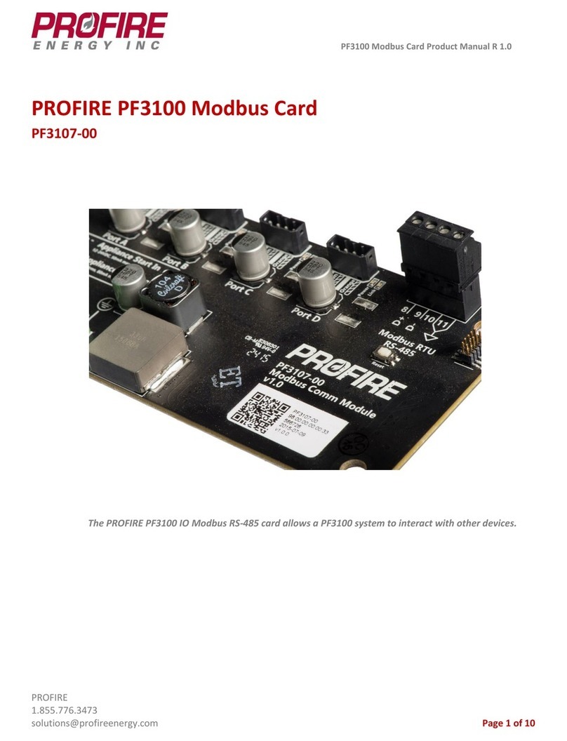
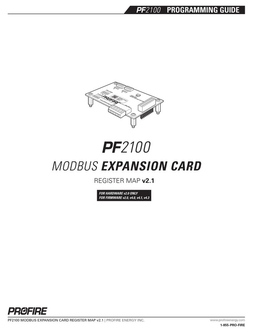
ProFire PF3102-00A User manual

PF3100 Ion Pilot Card Product Manual R 1.0
PROFIRE
1.855.776.3473
solutions@profireenergy.com Page 1 of 12
PROFIRE PF3100 Ion Pilot Card
PF3102-00
The PROFIRE PF3100 Ion Pilot card is an igniter and uses ionization to detect flame.

PF3100 Ion Pilot Card Product Manual
PROFIRE
1.855.776.3473
solutions@profireenergy.com Page 2 of 12
1. Introduction ..........................................................................................................................................3
2. Certifications .........................................................................................................................................3
3. Card Information ...................................................................................................................................4
4. Wiring Diagram......................................................................................................................................6
5. Mounting Instructions............................................................................................................................9
6. Enclosure Specifications....................................................................................................................... 10
7. Instructions for Use.............................................................................................................................. 10
8. Preventative Maintenance & Inspection............................................................................................... 10
9. Important Safety Information .............................................................................................................. 11
10. PROFIRE Contact Information............................................................................................................... 12

PF3100 Ion Pilot Card Product Manual
PROFIRE
1.855.776.3473
solutions@profireenergy.com Page 3 of 12
1. Introduction
Functional Description
The PROFIRE PF3100 Ion Pilot card is used to generate a spark to ignite a pilot burner and to detect the flame
of both a pilot and main burner. This card is powered through the PFRN network via a controller or network
card (a BMS controller card, or a Network card).
Model Types
Model Number
Name
Description
PF3102-00A
Ion Pilot Card - Zone 1
Aluminum enclosure.
2. Certifications
PROFIRE strives to ensure that certifications are updated as quickly as they become available for all of our
products.
Ion Pilot Card - Hazardous Location Rating
Certification: Class I, Div 1, Grp BCD; T6, IP66, Type 4
IEC 61508 SIL 2, CSA 22.2 No. 60730-2-5, UL 60730-2-5.
The board includes the following symbols:
Caution: possibility of electric shock.
Caution: documentation must be consulted in all cases where this symbol is marked.

PF3100 Ion Pilot Card Product Manual
PROFIRE
1.855.776.3473
solutions@profireenergy.com Page 4 of 12
3. Card Information
Card Specifications
The ambient temperature rating for the Ion Pilot Card is -40°C (-40°F) to +60°C (+140°F).
Card Diagram

PF3100 Ion Pilot Card Product Manual
PROFIRE
1.855.776.3473
solutions@profireenergy.com Page 5 of 12
Terminal Specifications
Terminal
Number
Terminal
Name
Expected Connections
Input/Output
Safety Rated
Electrical Ratings
Voltage
Current
1
LEL In -
Connect to an external LEL sensor (4-
20mA or dry).
Digital/4-20mA Input
Yes
0-15 VDC
25mA
2
LEL In +
12/24VDC Power Output
Yes
12 VDC
50mA
3
Valve -
Connect to Pilot Valve terminal . Do
NOT connect to ground.
Powered Output
Yes
0-12 VDC
1A
4
Valve +
Connect to Pilot Valve terminal 1.
Powered Output
Yes
5
Main Ion +
Connect to main flame rod.
Flame Ionization Input
Yes
200 VAC
10mA
6
Ion +
For a dual rod configuration:
connect to the pilot flame rod. For a
single rod configuration, connect to
the Ion + terminal of the coil (red
wire).
Flame Ionization Input
Yes
200VAC
10mA
7
EGND
Earth Ground and Enclosure Ground
Ground
N/A
N/A
N/A
8
Coil -
Connect to the primary winding of
the ignition coil (black wire).
Coil Drive Output
Yes
N/A
N/A
9
Coil +
Connect to the primary winding of
the ignition coil (white wire).
Coil Drive Output
Yes
14 VDC
360mA
Terminal Descriptions
Main Ion, Pilot Ion
Connect each of these inputs to a Kanthal flame rod placed directly in the pilot/main flame. The pilot and
main nozzles must be grounded for the flame detection to function properly. These inputs are protected
from high voltage, and can be connected in series with the high voltage terminals of an external ignition coil;
this allows a single flame rod to be used for both pilot ignition and pilot flame detection. A 65 VAC (voltage
AC) signal is applied to the flame rod. The source impedance is very high, so there is no danger of sparking
during detection.
Coil
Connect the primary terminal of the ignition coil to these terminals. A 12V pulsed DC signal is applied by the
card to the coil. This output is protected by a 250mA thermal fuse.
LEL In
This input can be connected to an optional LEL (Lower Explosive Limit) sensor to detect explosive gas
concentrations in the burner housing. The input can be configured in software to be disabled, to require an
LEL switch, or to require an LEL 4-20mA transmitter. The system will not start if the contact is open, or if the

PF3100 Ion Pilot Card Product Manual
PROFIRE
1.855.776.3473
solutions@profireenergy.com Page 6 of 12
4-20mA LEL input is above the trip point. It also has Aux In capability and can be used for thermocouple flame
detection.
Valve
Solenoid valves must be connected between the positive and negative terminals. The negative terminal is
NOT directly connected to ground. This output is driven by 12V and will only work with 12V solenoid valves.
EGND
This terminal must be connected to the same earth ground as the pilot and main burner assemblies. Modules
come pre-wired with a connection to the enclosure ground lug, which must be connected to earth ground.
4. Wiring Diagram
General Wiring Diagram

PF3100 Ion Pilot Card Product Manual
PROFIRE
1.855.776.3473
solutions@profireenergy.com Page 7 of 12
Single Rod Pilot Wiring
The single rod pilot configuration is used for a single rod for flame detection and pilot detection.
Older Model with Gen 2 Coil
Newer Model with Gen 3 Coil

PF3100 Ion Pilot Card Product Manual
PROFIRE
1.855.776.3473
solutions@profireenergy.com Page 8 of 12
Dual Rod Pilot Wiring
Dual rod configuration is used when two separate rods for pilot ignition and flame detection are used.
Older Model with Gen 2 Coil
Newer Model with Gen 3 Coil

PF3100 Ion Pilot Card Product Manual
PROFIRE
1.855.776.3473
solutions@profireenergy.com Page 9 of 12
Wiring Specifications
Wire
Location
Connection Description
Wire Type and
Minimum Gauge
Maximum Length
5
Board to Main Flame Detect Rod
7mm (0.25
inches) ignition
wire
Wire should be
limited to 3 meters
(10 ft).
6
Board to Pilot Flame Detect (Dual
Rod Pilot only)
7mm (0.25
inches) ignition
wire
Wire should be
limited to 3 meters
(10 ft).
7
Board to Burner
14 AWG
Wire should be
limited to 3 meters
(10 ft).
10
Coil to Pilot Ignition Rod
7mm (0.25
inches) ignition
wire
Wire should be
limited to 3 meters
(10 ft).
5. Mounting Instructions
Mounting the Card in the Enclosure
1. Install four (4) #10-32 screws through the Ion Pilot card (as indicated in the image below) and attach them
to the upper set of enclosure stand-offs. Please note the board orientation.
2. Torque to 26 in*lb.

PF3100 Ion Pilot Card Product Manual
PROFIRE
1.855.776.3473
solutions@profireenergy.com Page 10 of 12
6. Enclosure Specifications
The Ion Pilot card is mounted in the EPX enclosure
Specifications
EPX Enclosure
Dimensions
Top Width 11.7cm (4.61 inches)
Base Width 16.8cm (6.63 inches)
Height 21.7cm (8.53 inches)
Depth 13.3cm (5.25 inches)
Hazloc Rating
Class I, Div 1, GRP BCD, Type 4x; Class I, Zone 1, Aex d IIB + H2 T6
Gb; Ex db IIB + H2 T6 Gb, IECEx
Mounting
Channel Bar or Direct Mount
Enclosure Construction
Aluminum
Operating Temperature
-40°C (-40°F) to 60°C (140°F)
Storage Temperature
-40°C (-40°F) to 60°C (140°F)
7. Instructions for Use
The Ion Pilot card is designed to be used with the PF3101-00 BMS controller card as part of the PF3100 platform.
Operation
Operating controls and their uses are described under “Terminal Descriptions” above.
8. Preventative Maintenance & Inspection
In order to ensure that the Ion Pilot card works correctly and efficiently, the following maintenance and
inspection procedures should be followed:
➢Ensure that all wires are connected correctly.
➢Minimize copper wire exposure.
➢Check for corrosion and ensure that no wires are frayed or worn, and all insulation is intact.
➢Confirm no moisture or condensation is apparent on the board or in the enclosure.
➢Ensure that the board does not show any sign of mechanical damage (e.g. –damage from an impact such as
dropping an item).
➢Check that the board does not show any sign of electrical damage (components should not be burnt or
damaged in any way).
➢Confirm that the temperature of the board is within ambient temperature operating limits.
➢Check that the enclosure is secured and that the device is not subject to excessive vibration.
➢Routine inspections of all equipment should be performed. If any abnormality is found, corrective actions
should be taken. If the abnormality cannot be corrected, contact PROFIRE.
➢A qualified technician should perform any tests necessary to confirm that the equipment is still in a safe
condition.
oEnsure power LED is lit (blue)

PF3100 Ion Pilot Card Product Manual
PROFIRE
1.855.776.3473
solutions@profireenergy.com Page 11 of 12
oEnsure link LED is lit (green)
oDisconnect ignition wire from coil and measure from ignition wire to EGND to ensure there is no
continuity.
oWith the ignition wire disconnected, measure from ION+ to EGND in volts AC. A functional board
will have a measurement between 17-38 VAC.
oPlug the ignition wire back into the coil and repeat the prior test. This test should show the same
readings as before. If not, there is a short between the ignition wire or rod and EGND.
Cleaning
If the card becomes dirty it can be cleaned with compressed air. Do NOT use solvents, cleaners, or liquids to
clean the board. Caution must be exercised when cleaning the board in order to prevent damage from ESD
(electrostatic discharge).
Replacement Parts
Please contact PROFIRE should any replacement parts be required.
9. Important Safety Information
Before installing the PF3100 Ion Pilot card, please review the list of warnings below. Product use in a manner
not specified by PROFIRE is not recommended. Failure to observe the following warnings may result in death,
electrocution, property damage, product damage, product damage, government fines, or malfunction of the
product itself.
WARNING: Explosion Hazard
➢Do not disconnect while circuit is live unless area is known to be non-hazardous or equivalent.
➢Substitution of components may impair suitability for specified zones.
➢Do not service unless the area is known to be non-hazardous.
➢Do not open when energized.
➢Installation and use must conform to the directions in this guide.
➢System must be properly connected to earth-ground for effective operation of flame detection
circuitry.
Installation Warnings
➢Ensure that the PF3100 enclosures are securely closed each time after opening the enclosure. This
protects the internal circuitry from moisture damage and other environmental concerns. Moisture
damage is not covered by the product warranty.
➢Do not connect wires or handle the device when powered.
➢Properly fuse the board according to local codes.
➢Do not disassemble or modify the board in any way. The board is not field repairable and must be sent
back to PROFIRE for replacement if damaged.
➢Check the spark gap for the igniter. Optimally it should have a spark gap around 1/4”.

PF3100 Ion Pilot Card Product Manual
PROFIRE
1.855.776.3473
solutions@profireenergy.com Page 12 of 12
➢There is a high potential for electric shock due to the high voltages of the ignition coil. The Coil + and
Coil –terminals, as well as the Ion+ and the secondary of the ignition coil all pose this risk.
10. PROFIRE Contact Information
If you have any concerns or questions about this product, please contact PROFIRE as follows:
U.S.
1.801.796.5127
321 South, 1250 West Suite 1
Lindon, UT
84042, USA
solutions@profireenergy.com
CANADA
1.780.960.5278
Box 3313, Bay 12, 55 Alberta Ave
Spruce Grove, AB
T7X 3A6, Canada
solutions@profireenergy.com
http://www.profireenergy.com
Table of contents
Other ProFire Control Unit manuals
Popular Control Unit manuals by other brands
Circor
Circor D Series his document is the property of Circor Flow Technologies India Pvt Limited should not copiINSTALLATI

bee
bee KSN77 PN 16 Operating and assembly instruction
Siemens
Siemens SIPROTEC PROFINET IO manual
Monacor
Monacor TXA-802MBT manual

King gates
King gates Star 2230 instruction manual

Kübler
Kübler BM Series manual
Momentum
Momentum MN 39 Series Operator's manual

ADTRAN
ADTRAN ATLAS 800 Series Module QUAD E1 user manual
CandCNC
CandCNC THC Sensor PWM Setting up
Minebea Intec
Minebea Intec Combics YDO07-X installation instructions

Vag
Vag GA Figure 220-D Installation, operation and maintenance manual
Satel
Satel ETHM-1 Plus Quick installation guide
