Prology DVD-557 User manual

S P E C IF IC ATION
S E R VIC E MANUAL
C AR DVD P LAY E R
P R OL OG Y DVD-557
P ower requirement 12 V DC car battery
(negative earth)
oo
Operating temperature -10 C to +70 C
Dimens ions Approx 50mm x178mm
x165mm
(W/h/d)
oo
S torage temperature: -30 C ~ +80 C
Operational humidity: 45% ~80%R H
Atmos phere pressure: 860mbar~1060mbar
TAB LE OF C ONT E NT S
1. G E NE R AL ___________________________________________ 2-3
2. B L OC K DIAG R AM_____________________________________ 4-5
3. E LE C T R IC AL T R O UB LE S HOOT ING G UIDE ________________ 6-21
4. P R INTE D C IR C UIT _____________________________________ 22-28
5. E LE C T R IC AL P AR TS LIS T____________________________ 29-40
1

PRODUCT SAFETY SERVICING GUIDELINES FOR VIDEO PRODUCTS
CAUTION: DO NOT ATTEMPT TO MODIFY THIS PRODUCT IN ANY WAY AND NEVER SUBJECT: X-RADIATION
PERFORM CUSTOMIZED INSTALLATIONS WITHOUT MANUFACTURER'S APPROVAL.
NAUTHORIZED MODIFICATIONS WILL NOT ONLY VOID THE WARRANTY, BUT MAY LEAD TO 1.BE SURE PROCEDURES AND INSTRUCTIONS TO ALL SERVICE PERSONNEL COVER THE
YOUR BEING LIABLE FOR ANY RESULTING PROPERTY DAMAGE OR USER INJURY. SUBJECT OF X-RADIATION. THE ONLY POTENTIAL SOURCE OF X-RAYS IN CURRENT T.V.
RECEIVERS IS THE PICTURE TUBE. HOWEVER, THIS TUBE DOES NOT EMIT X-RYS WHEN THE
SERVICE WORK SHOULD BE PERFORMED ONLY AFTER YOU ARE THOROUGHLY FAMILIAR HIGH VOLTAGE IS AT THE FACTORY SPECIFIED LEVEL. THE PROPER VALUE IS GIVEN IN THE
WITH ALL OF THE FOLLOWING SAFETY CHECKS AND SERVICING GUIDELINES. TO DO APPLICABLE SCHEMATIC. OPERATION AT HIGHER VOLTAGES MAY CAUSE A FAILURE OF
OTHERWISE, INCREASES THE RISK OF POTENTIAL HAZARDS AND INJURY TO THE USER. THE PICTURE TUBE OR HIGH VOLTAGE SUPPLY AND, UNDER CERTAIN CIRCUMSTANCES,
MAY PRODUCE RADIATION IN EXCESS OF DESIRABLE LEVELS.
.WHILE SERVICING, USE AN ISOLATION TRANSFORMER FOR PROTECTION FROM A.C. LINE
SHOCK. 2. ONLY FACTORY SPECIFIED C.R.T ANODE CONNECTORS MUST BE USED
DEGAUSSING SHIELDS ALSO SERVE AS AN X-RAY SHIELD IN COLOR SETS,
SAFETY CHECKS ALWAYS RE-INSTALL THEM.
AFTER THE ORIGINAL SERVICE PROBLEM HAS BEEN CORRECTED, A CHECK SHOULD BE 3. IT IS ESSENTIAL THAT SERVICE PERSONNEL HAVE AVAILABLE AN ACCURATE AND
MADE OF THE FOLLOWING. RELIABLE HIGH VOLTAGE METER. THE CALIBRATION OF THE METER SHOULD BE CHECKED
PERIODICALLY AGAINST A REFERENCE STANDARD, SUCH AS THE ONE AVAILABLE AT YOUR
DISTRIBUTOR.
SUBJECT: FIRE & SHOCK HAZARD
4. WHEN THE HIGH VOLTAGE CIRCUITRY IS OPERATING PROPERLY, THERE IS NO
1. BE SURE THAT ALL COMPONENTS ARE POSITIONED IN SUCH A WAY AS TO AVOID POSSIBILITY OF AN ACCURATE AND RELIABLE HIGH VOLTAGE METER. THE CALIBRATION OF
POSSIBILITY OF ADJACENT COMPONENT SHORTS. THIS IS ESPECIALLY IMPORTANT ON THE METER SHOULD BE CHECKED PERIODICALLY AGAINST A REFERENCE STANDARD,
THOSE MODULES WITCH ARE TRANSPORTED TO AND FROM THE REPAIR SHOP. SUCH AS THE ONE AVAILABLE AT YOUR DISTRIBUTOR.
2. NEVER RELEASE A REPAIR UNLESS ALL PROTECTIVE DEVICES SUCH AS INSULATORS, 5. WHEN TROUBLESHOOTING AND MAKING TEST MEASUREMENTS IN A PRODUCT WITH A
BARRIERS, COVERS, SHIELDS, STRAIN RELIEFS, POWER SUPPLY CORDS, AND OTHER PROBLEM OF EXCESSIVE HIGH VOLTAGE AVOID BEING UNNECESSARILY CLOSE TO THE
HARDWARE HAVE BEEN REINSTALLED PER ORIGINAL DESIGN. BE SURE THAT THE SAFETY PICTURE TUBE AND THE HIGH VOLTAGE SUPPLY DO NOT OPERATE THE PRODUCT LONGER
PURPOSE OF THE POLARIZED LINE PLUG HAS NOT BEEN DEFEATED. THAN IT IS NECESSARY TO LOCATE THE CAUSE OF EXCESSIVE VOLTAGE.
3. SOLDERING MUST BE INSPECTED TO DISCOVER POSSIBLE COLD SOLDER JOINTS, 6. REFER TO HV. B+ AND SHUTDOWN ADJUSTMENT PROCEDURES DESCRIBED IN THE
SOLDER SPLASHES OR SHARP SOLDER POINTS. BE CERTAIN TO REMOVE ALL LOOSE APPROPRIATE SCHEMATIC AND DIAGRAMS(WHERE USED).
FOREIGN PARTICLES.
4. CHECK FOR PHYSICAL EVIDENCE DF DAMAGE OR DETERIORATION TO PARTS AND SUBJECT: IMPLOSION
COMPONENTS, FOR FRAYED LEADS AND DAMAGED INSULATION (INCLUDING A.C.
CORD), AND REPLACE IF NECESSARY FOLLOW ORIGINAL LAYOUT, LEAD LENGTH AND 1. ALL DIRECT VIEWED PICTURE TUBES ARE EQUIPPED WITH AN INTEGRAL IMPLOSION
DRESS. PROTECTION SYSTEM, BUT CARE SHOULD BE TAKEN TO AVOID DAMAGE DURING
INSTALLATION, AVOID SCRATCHING THE TUBE. IF SCRATCHED REPLACE IT.
5. NO LEAD OR COMPONENT SHOULD TOUCH A RECEIVING TUBE OR A RESISTOR RATED
AT 1 WATT OR MORE. LEAD TENSION AROUND PROTRUDING METAL SURFACES MUST BE 2. USE ONLY RECOMMENDED FACTORY REPLACEMENT TUBES.
AVOIDED.
SUBJECT: TIPS ON PROPER INSTALLATION
6. ALL CRITICAL COMPONENTS SUCH AS FUSES. FLAMEPROOF RESISTORS, CAPACITORS,
ETC. MUST BE REPLACED WITH EXACT FACTORY TYPES, DO NOT USE REPLACEMENT
COMPONENTS OTHER THAN THOSE SPECIFIED OR MAKE UNRECOMMENDED CIRCUIT 1. NEVER INSTALL ANY PRODUCT IN A CLOSED-IN RECESS. CUBBYHOLE OR CLOSELY
MODIFICATIONS. FITTING SHELF SPACE, OVER OR CLOSE TO HEAT DUCT, OR IN THE PATH OF HEATED AIR
FLOW.
7. AFTER RE-ASSEMBLY OF THE SET, ALWAYS PERFORM AN A.C. LEAKAGE TEST ON ALL
EXPOSED METALLIC PARTS OF THE CABINET, (THE CHANNEL SELECTOR KNOB, ANTENNA 2. AVOID CONDITIONS OF HIGH HUMIDITY SUCH AS: OUTDOOR PATIO INSTALLATIONS
TERMINALS. HANDLE AND SCREWS) TO BE SURE THE SET IS SAFE TO OPERATE WITHOUT WHERE DEW IS A FACTOR, NEAR STEAM RADIATORS WHERE STEAM LEAKAGE IS A FACTOR,
DANGER OF ELECTRICAL SHOCK. DO NOT USE A LINE ISOLATION TRANSFORMER DURING ETC.
THIS TEST, MAKE SURE TO USE AN A.C. VOLTMETER. HAVING 5000 OHMS PER VOLT OR
MORE SENSITIVITY, IN THE FOLLOWING MANNER; CONNECT A 1500 OHMS 10 WATT 3. AVOID PLACEMENT WHERE DRAPERIES MAY OBSTRUCT REAR VENTING. THE CUSTOMER
RESISTOR, PARALLELED BY A.15 MFD. 150V A.C. TYPE CAPACITOR BETWEEN A KNOWN SHOULD ALSO AVOID THE USE OF DECORATIVE. SCARVES OR OTHER COVERINGS WHICH
GOOD EARTH GROUND (WATER PIPE, CONDUIT, ETC.) AND THE EXPOSED METALLIC PARTS, MIGHT OBSTRUCT VENTILATION.
ONE AT A TIME. MEASURE THE A.C. VOLTAGE ACROSS THE COMBINATION OF 1500 OHM 4. WALL AND SHELF MOUNTED INSTALLATIONS USING A COMMERCIAL MOUNTING KIT,
RESISTOR AND 15 MFD CAPACITOR. REVERSE THE A.C. PLUG AND REPEAT A.C. ANY MUST FOLLOW THE FACTORY APPROVED MOUNTING INSTRUCTIONS. A PRODUCT
VOLTAGE MEASUREMENTS FOR EACH EXPOSED METALLIC PART. VOLTAGE MEASURED MOUNTED TO A SHELF OR PLATFORM MUST RETAIN ITS ORIGINAL FEET (OR THE
MUST NOT EXCEED 75 VOLTS R.M.S. THIS CORRESPONDS TO 0.5 MILLIAMP A.C. ANY EQUIVALENT THICKNESS IN SPACERS). TO PROVIDE ADEQUATE AIR FLOW ACROSS THE
VALUE EXCEEDING THIS LIMIT CONSTITUTES A POTENTIAL SHOCK HAZARD AND MUST BE BOTTOM. BOLTS OR SCREWS USED FOR FASTENERS MUST NOT TOUCH ANY PARTS OR
CORRECTED IMMEDIATELY. WIRING. PERFORM LEAKAGE TEST ON CUSTOMIZED INSTALLATIONS.
5. CAUTION CUSTOMERS AGAINST THE MOUNTING OF A PRODUCT ON SLOPING SHELF
OR A TILTED POSITION, UNLESS THE PRODUCT IS PROPERLY SECURED.
6. A PRODUCT ON A ROLL-ABOUT CART SHOULD BE STABLE ON ITS MOUNTING TO THE
CART CAUTION THE CUSTOMER ON THE HAZARDS OF TRYING TO ROLL A CART WITH
SMALL CASTERS ACROSS THRESHOLDS OR DEEP PILE CARPETS.
7. CAUTION CUSTOMERS AGAINST THE USE OF A CART OR STAND WHICH HAS NOT BEEN
GOOD EARTH GROUND LISTED BY UNDERWRITERS LABORATORIES, INC. FOR USE WITH THEIR SPECIFIC MODEL OF
SUCH AS THE WATER TELEVISION RECEIVER OR GENERICALLY APPROVED FOR USE WITH TV'S OF THE SAME OR
PIPE, CONDUIT, ETC. LARGER SCREEN SIZE.
8. CAUTION CUSTOMERS AGAINST THE USE OF EXTENSION CORDS. EXPLAIN THAT A
FOREST OF EXTENSIONS SPROUTING FROM A SINGLE OUTLET CAN LEAD TO DISASTROUS
SUBJECT GRAPHIC SYMBOLS CONSEQUENCES TO HOME AND FAMILY.
The lightening flash with arrowhead symbol, within an equilateral
triangle, is intended to alert the user to the presence of uninsulated
"dangerous voltage" within the product's enclosure that may be of
sufficient magnitude to constitute a risk of electric shock to persons.
The exclamation point within an equilateral triangle is intended to alert
the user to the presence of important operating and maintenance
(servicing) instructions in the literature accompanying the appliance.
PLACE THIS PROBE
ON EACH EXPOSED
METAL PART
2

CAUTION : Before servicing the DVD covered by this service Electrostatically Sensitive (ES) Devices
data and its supplements and ADDENDUMS, read and Some semiconductor (solid state) devices can be
follow the SAFETY PRECAUTIONS NOTE : if unforeseen damaged easily by static electricity. Such components
circumstances create conflict between the following commonly are called Electrostatically Sensitive (ES) Devices.
servicing precautions and any of the safety precautions in Examples of typical ES devices are integrated circuits and
this publications, always follow the safety Precautions. some field effect transistors and semiconductor chip
Remember Safety First: components. The following techniques should be used to
help reduce the incidence of component damage
caused by static electricity.
General Servicing Precautions
1. Immediately before handling any emiconductor
1. Always unplug the DVD DC power cord from the DC component or semiconductor-equipped assembly, drain
power source before: off any electrostatic charge on your body by touching a
(1) Removing or reinstalling any component, circuit board, known earth ground. Alternatively, obtain and wear a
module, or any other assembly. commercially available discharging wrist strap device,
(2) Disconnection or reconnecting any internal electrical which should be removed for potential shock reasons
plug or other electrical connection. prior to applying power to the unit under test.
Caution : A wrong part substitution or incorrect polarity
installation of electrolytic capacitors may result in an 2. After removing an electrical assembly equipped with ES
explosion hazard. devices, place the assembly on a conductive surface
such as aluminum toil, to prevent electrostatic charge
2. Do not spray chemicals on or near this DVD or any of its buildup or exposure of the assembly.
assemblies.
3. Use only a GROUNDED-tip soldering iron to solder or
3. Unless specified otherwise in this service data, clean unsolder ES devices.
electrical contacts by applying an appropriate contact
cleaning solution to the contacts with a pipe cleaner, 4. Use only an anti-static solder removal device. Some
cotton-tipped swab, or comparable soft applicator. solder removal devices not classified a "anti-static" can
Unless specified otherwise in this service data, lubrication generate electrical charges sufficient to damage ES
of contacts is not required. devices.
4. Do not defeat any plug/socket B+ voltage interlocks with 5. Do not use freon-propelled chemicals. These can
which instruments covered by this service manual might generate electrical charge sufficient to damage ES
be equipped. devices.
5. Do not apply AC power to this DVD and/or any of its 6. Do not remove a replacement ES device from its
electrical assemblies unless all solid-state device heat protective package until immediately before you are
sinks are correctly installed ready to install it. (Most replacement ES devices are
.packaged with leads electrically shorted together by
6. Always connect test instrument ground lead to the conductive foam, aluminum foil, or comparable
appropriate ground before connection the test conductive material.)
instrument positive lead. Always remove the test
instrument ground lead last. 7. Immediately before removing the protective material
from the leads of a replacement ES device, touch the
protective material to the chassis or circuit assembly into
Insulation Checking Procedure which the device will be installed.
Disconnect the attachment plug trom the AC outlet and Caution : Be sure no power is applied to the chassis or
turn the power on. Connect an insulation resistance circuit, and observe all other safety precautions.
meter(500V) to the blades of the attachment plug. The
insulation resistance between each blade of the 8. Minimize bodily motions when handling unpackaged
attachment plug and accessible conductive parts (Note 1) replacement ES devices. (Normally harmless motion
should be more than 1M ohm. such as the brushing together of your clothes fabric or
the lifting of your foot from a carpeted floor can
Note 1 : Accessible Conductive Parts including Metal generate static electricity sufficient to damage an ES
panels, input terminals, Earphone jacks, etc. device.)
SERVICING PRECAUTIONS
3

TR+
FO+
TR-
FO-
VCC
GND
GND
LD
V/2
VR
PD
VC
VA
GND
VB
VD
VDS
GND
V/2
VCC
GND
LD
VC
VR
PD
VA
VE
GND
VF
VB
1
10
20
30
CN2
CN7
1SLOAD-
SLOAD+
CN3
A2
A1
H-
H1-
H1+
H2-
H2+
H3-
H3+
H+
1
11
CN6
1SLED+
SLED-
CN8
1SW1-1
RFGND
CN5
1 SW-1
SW-2
GND
SW-4/6
GND
SW-3
TO PICK UP MECHANISM CHASSIS
TO PICK UP MECHANISM CHASSIS
RF AMP
U2
SP3721
SERVO
&TRAY
DRIVER
BA5954
&BA6849
SERVO AND DVD PROCESSOR
M5705
33.8688MHz
MPEG-2 DECODER
U5
VEDIO ENCODER
EEPROM
W29C011AP-15
16MSDRAM
HY57V16160DTC
16MSDRAM
HY57V16160DTC
8MFLASH
CS4340
AUDIO DAC
CN202
1
10
+5V
+5V
+5V
DGND
DGND
DGND
DGND
+12V
SLOAD-
SLOAD+
CN203
1
10
20
AGND
AGND
SW1
SW2
SW4/6
SW3
STB
DATA
CLK
MPEG_CMD
L
R
PARKING
AGND
AGND
AGND
AGND
MIC_ON
AGND
AIN
AGND
VD
AGND
AMUTE
1
CVBS1
CVBS2
SPDIF
VGND
VGND
DGND
CN204
U9 U10
U1
U8
U7
SST39VF800
U12
U502
TO MAIN BOARD
TO MAIN BOARD
SERVO AND DECODER BOARD
U4
A3
TO PICK UP
MECHANISM
CHASSIS
TO PICK UP
MECHANISM
CHASSIS
TO PICK UP
MECHANISM
CHASSIS
27MHz
Y1
Y3
BLOCK DIAGRAM
TO THE
EXTERIOR
TO PICK UP
MECHANISM
CHASSIS
4

MAINBORAD BLOCK DIAGRAM
+5V
+5V
+5V
DGND
DGND
DGND
+12V
SLOAD-
SLOAD+
1
10
20
AGND
AGND
SW1
SW2
SW4/6
SW3
STB
DATA
CLK
MPEG_CMD
L
R
PARKING
AGND
AGND
AGND
AGND
MIC_ON
AGND
AIN
AGND
VD
AGND
AMUTE
1
10
DGND
DGND
LCD_INH
CCB-LCD-CE
CCB-LCD-DO
CCB-CL
CCB-DI
PAN_INH
SW4-6
POWER-LED
EJECT
ENCODER_B
ENCODER_A
8V
REMOTE
P5V
U201
TMP87CM21DF-100
LB1641
TEA6320T
8M 32.768k
1
AUXL
AAGND
AAGND
AUXR
BA3121F
U504
U301
TDA7386
TLC2272
U601 U602
U503
GND
LIGHT
PAKING
TEL MUTE
FL-
FL+
FR-
FR+
RR+
RR-
RL+
RL-
AMP.CONT
AUTO.CONT
ACC+
B+
1
10
1
10
BUS
B+
AGND
ACC
NC
R-CH
L-CH
VM1
DGND
DGND
DGND
1
FRONT-L
FRONT-R
AGND
AGND
AGND
SBW
CN601
REAR-L
REAR-R
AGND
AGND
CN604
TLC2272
U604
U701
Pt2257
U706
TLC2272
U101
TC9257F
U102
FAE347-A28
U707
LC72722M
TO KEY BOARD
TO SERVO AND DECODER BORAD
TO SERVO AND DECODER BORAD
OPERATIONAL AMPLIFIER
POWER AMPLIFIER
SOUND FADER CONTROL
8BIT MCU
U203
MOTOR DIRVER
TUNER RECEIVER
GROUND ISOLATION AMPLIFIER
RDS
Signal-Processing
PLL
OPERATIONAL
AMPLIFIER
DGND
CN201
CN402
1
10
CN301CN2 CN501
7.2M
TO THE
EXTERIOR
TO THE
EXTERIOR
TO THE
EXTERIOR
TO THE
EXTERIOR
TO THE
EXTERIOR
BA3121F
U501
GROUND ISOLATION AMPLIFIER
5

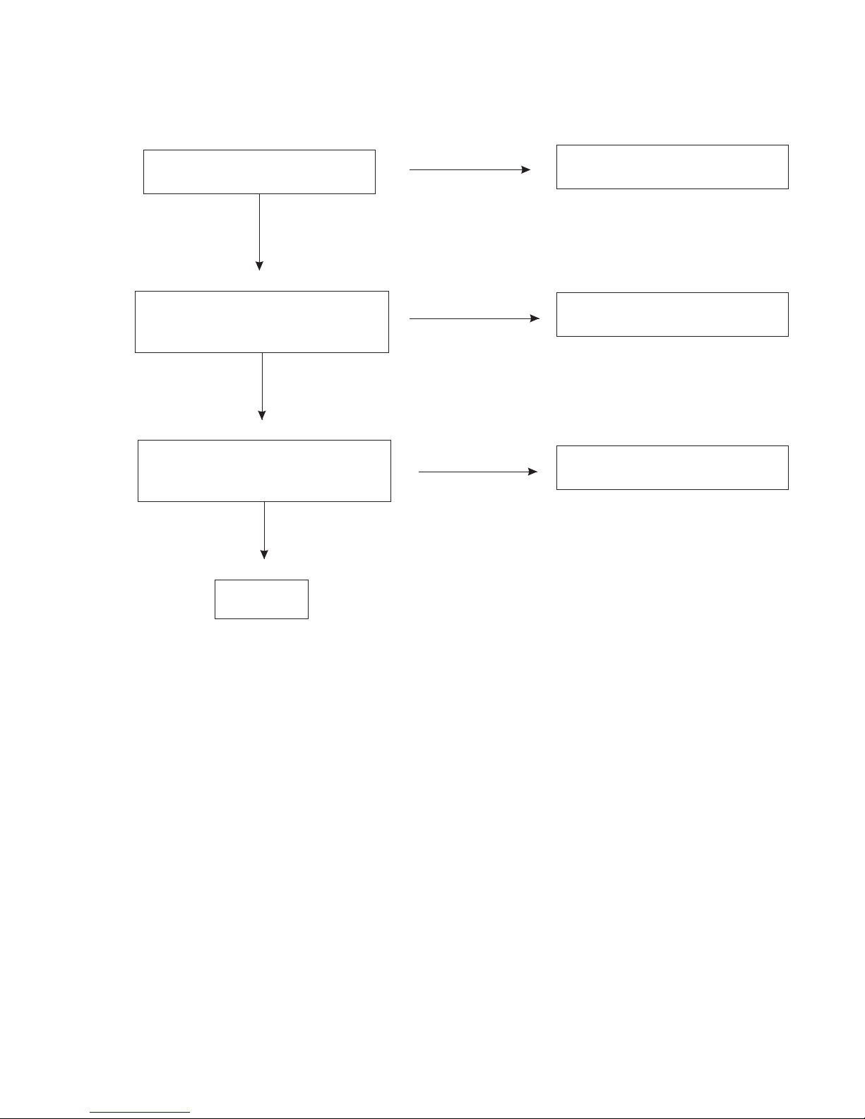
Electrical Trouble Shooting Guide
Connection of unit is correct
Setting of unit is correct
Is power noraml?
Is fluoresce
display corrct?
Is open/close
noraml?
Is audio normal?
Can disc be read?
Is video normal?
Normal
Refer to power guide
Refer to display guide
Refer to open/close guide
Refer to read disc guide
Refer to video guide
Refer to audio guide
NO
YES
YES
YES
YES
YES
YES
NO
NO
NO
NO
NO
Is LOGOout? Refer to logo guide
YES
NO
Is tuner normal? Refer to tuner guide
YES
NO
Is CDC normal? Refer to cdc guide
YES
NO
6

A Power Circuit abnormal(For main board)
START
Is 1pin of Q404 DC 12V? Check D307
Is 40pin of U201 DC 5V?
Is 33pin of U201 DC 5V?
Is 5pin of Q404 DC 12V?
Is 2pin of U404 DC 5V?
Is net of 8V DC 8V?
Is 39pin of U201 DC 3.3V?
Normal
YES
NO
Check Q401 U403 L401and peripheral
components.
Check U201 and peripheral components
Check Q404 Q408 and peripheral components
Check U404 and peripheral components
Check ZD439 and peripheral components
Check U402 and peripheral
components
YES
YES
YES
YES
YES
NO
NO
NO
NO
NO
NO
Is 26pin of U201 DC 5V?
Check Zd401 and peripheral components.
NO
YES
Check ACC and ACC fuse.
7

B Display abnormal (For main board)
START
Does the screen appear?
Is display normal?
Normal
Check if pin14 of CN201voltage of DC 8V?
Check if pin 16 of 201 voltage of DC5V?
Check the key board according to key
schematic
Cn
Check the key board according to key
schematic
YES
NO
YES
NO
8

C IN/OUT abnormal (For main board)
THE disc can't be injected
Is 7,8pin of Lb1641 DC 12V?
Is Voltagebetween 2 and 10pin ofLb1641
DC 4.6V after eject-key being pressed?
Is voltage between 2 and 1pin of
cn7 at S&D board DC 4.5V?
Check R205 R245 L201
2.Check Zd201 ,Lb1641
Check connection between main
board and S&D board
1.Check cn8 at S&D board , connection
between it and MCU
Normal
YES
YES
YES
NO
NO
NO
9

D Logo Display abnormal(For S&D board(SERVO and Decoder board))
Is vlotage for CN202 normal?
No Logo display
Having picture,no color or color
disappered during playback.
Check Connection of Main board and
S&D board
Change S&D board
Check decoder part and change Y1
Normal
YES
NO
YES
NO
YES
NO
10

E Read disc abnormal(For S&D board)
DISC IN
Focus on?
Is laser normal?
Does the disc turn?
Can TOC be read?
Refer to Focus abnormal
Refer to laser abnormal
Refer to disc turn abnormal
Refer to TOC abnormal
Normal
YES
YES
YES
YES
NO
NO
NO
NO
11
F Video abnormal
Only Logo display
Having picture, no colour or colour
disappeared during playback.
Having picture, but picture
disappeared during playback.
Check the connection of M5705 and Zr36748
Check decoder part and change Y2
Check decoder part and change Y2
Normal
YES
YES
YES
NO
NO
NO
12

G Audio abnormal(For main board)
Is the rear channel normal?
Is the front channel and
sbw channel normal?
Is the power amplifier
normal?
Normal
Refer to rear out abnormal
Refer to front out abnormal
YES
YES
YES
NO
NO
NO Check U301 and peripheral components.
13

H Turner abnormal(For main board)
Auto search abnormal
Is 13pin of U101 9V?
Is X101 oscillating?
Is 12pin of U101 9V at FM
mode and 0V at AM mode?
Normal
Autosearch normal
but audio abnormal
Is 3,4,29,30pin of
U503 normal?
Normal
RDS abnormal
Normal
Check P9V, if P9V is 9V,check Q110 Q115
and peripheral components.
If P9V is 0V, check according to main board
power schematic
Check Tc9257 X101 and peripheral components
Check 17pin of Tc9257 Q103 Q108 and
peripheral components
Check connection between 16,17pin of U101
and U503
Replace U503
Check U707 and peripheral components
YES
YES
YES
YES
YES
YES
NO
NO
NO
NO
NO
NO
14

I CDC abnormal(For main board)
CDC does not work
Is 2,4pin of CDC normal? Check Fb503
Is connection of 1pin of CDC with U201 normal?
Normal
Check correlative print wire
CDC audio abnormal
Is 1,7pin of U501 normal?
Is 3,4,29,30pin ofU503 normal?
Normal
Is pin8 of U501 Dc9? If not, check correlative printed wire
else, check peripheral components.
If still abnormal, change U501
Check U503 and peripheral components.
Is 31pin of U503 DC9V?
If still abnormal, change U503
YES
YES
YES
YES
NO
NO
NO
NO
15

No focus
Does normal voltage at FO+
and FO- of CN2?
Does normal voltage
at U9 pin 14,7?
Does data output at U2 pin42?
Normal
J Focus abnormal(For S&D board)
1. Check connection cord..
2. Replace pickup
1.Check connection between 14,7pin of BA5954
and FCS+,FCS- of CN2
2.Check if Y3 normal operation
3.Check BA5954 and peripheral components.
1.Check connection between U2 and U9
2.Check connection between U2 and peripheral
components.
Check U2 and peripheral components.
Is 28,30,35,58pin of U2 DC5V?
Is normal voltage at 18,26,27pin of U2? Check U3 and peripheral components
YES
YES
YES
YES
YES
NO
NO
NO
NO
NO
16

No laser
Does normal voltage at pin 25 of U2?
K Laser abnormal(For S&D board)
Does normal voltage at 24,22pin of U2?
Does normal Voltage at cathode of D2,D3?
Normal
YES
YES
YES
1.Check connections between M5705 and
Sp3721
2.check Sp3721 and peripheral components.
Check Sp3721 and peripheral components
YES
Check Q1 Q2 and peripheral components
Change pick up
17

L Turn abnormal(For S&D board)
Disc doesn't turn
Check if voltage of H- and H+,H1-and H1+,H2-
and H2+,H3- and H3+ of CN3 are different.
Check If voltage of 11 and 12 pin of
U9 are different.
Check if voltage of 26 pin of U2 is normal
Check if voltage of 13,9 pin of u2 is normal
Normal
Check connection of mechanism
Check connections between Ba 5954 and
CN6
check Ba5954 and peripheral components
Check connections between Sp3721 pin 26
and Ba5954 pin 4,27
Check Sp3721 and peripheral components.
Check connections between U2 5,23 pins and
U1 pins 13,9
Check U1 and peripheral components
YES
YES
YES
YES
NO
NO
NO
NO
18

M TOC abnormal(For S&D board)
TOC does not read
Limited switch is closed.
Is laser on?
Is FOK normal?
Does normal A, B, C, D signal at 11-14
pin of U2?
Does normal RFIN at 2 pin of U1?
Normal
Refer to laser guide
Check slide motor and connections to decoder
board.
1.Check connections between 11,13 pin of U2
and 13pin of CN2
2.Check 12,14pin of U2 and 15pin of CN2
3.Replace pickup
1.Check connection between U1 and U2.
2.Check U2 and peripheral components
YES
YES
YES
NO
NO
NO
19

N Rear out abnormal(For main board)
Rear out no sound or
sound abnormal
Is the 13,15 pin of
CN603 normal?
Is the 4,14 pin of
U603 abnormal?
Is the 1,7 pin of
U604 abnormal?
Is mute control normal?
Normal
Check connections between Main board and
S&D board
Check connections between CN603 and U603
Check U604 and peripheral components
Check Q605 Q607 Q609 Q610 and peripheral
components
YES
YES
YES
YES
YES
NO
NO
NO
NO
20
Other manuals for DVD-557
1
Table of contents
Other Prology Car Video System manuals


