Promaker PRO-TR300 User manual

Corded Drill 300W
User’s Manual
Model No.: PRO-TR300
English: 2 I Español: 14

2

3

4
NOTE: BEFORE THE TOOL IS
USED FOR THE FIRST TIME, READ
THIS INSTRUCTION MANUAL
AND KEEP IT FOR FUTURE
REFERENCE.
DETAILED SAFETY REGULA TIONS
WARNING: Safety regulations must
be observed, when the device is
operated. This instruction manual and
general safety information should be
read for your own and bystanders
safety, before the tool is operated.
This instruction manual should be kept
for future reference.
REMEMBER: The operator or user is
responsible for accidents or hazards
occurring to other people or the
environment.
• When the tool is operated, work
safety and hygiene regulations in force
should be strictly observed.
• Before operation is commenced,
check the unwound power cord for
damage or wear.
• Before connecting to the power
source, always make sure the supply
voltage is compatible with the value
specied on the nameplate of the tool.
• The tool can be connected only to
an electrical system equipped with a
differential current protection that will
cut the power off when earth leakage
current exceeds 30 mA in less than 30
ms.
• Do not allow the tool to be operated
by children and people not familiarized
with the instruction manual.
• Before you begin working, make
sure there is enough free space and
proper lighting over the work station.
• Check the workpiece for correct
fastening.
• Do not use the tool in rooms with
explosive atmospheres.
• Make sure that ventilation holes of
the tool are passable and kept clean
during operation.
• Before cleaning, the tool must be
disconnected from power supply.
Clean the tool using a brush.
• Always use eye and ear protection.
• It is also recommended to use
personal protection equipment, such
as dust mask and protective apron.
• Do not attempt to repair the tool on
your own.
• All repairs should be performed
by a qualied person only, or in an
authorised service centre, using
original spare parts.
NOTE! The tools is intended for
indoor works.
Despite using the construction,
which is safe by design itself,
protection means and additional
safety features, there is always
a residual risk of injuries during
operation.
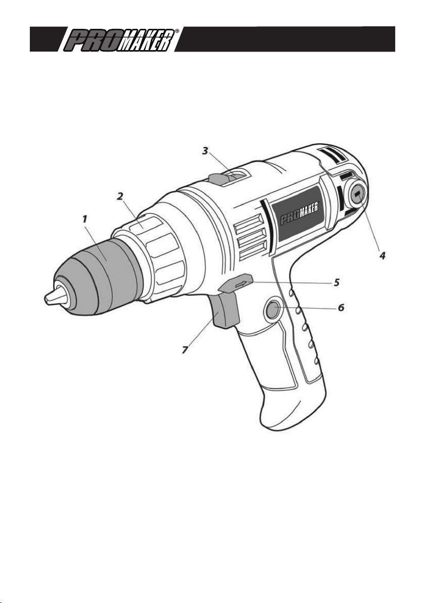
CONSTRUCTION AND APPLICATION
The drill and driver is an electric

5
hand tool driven with a single-phase
commutator motor, whose speed
is reduced by means of the gear
transmission. Power tools of this type
are widely used for tightening and
loosening of screws, making holes in
wood and wood-like materials, steel,
ceramics, etc. The electric drill and
driver can also be used with a series
of drill bits, sockets, screwdriver bits
of various lengths. The range of
applications of the drill driver include
renovation, carpentry, locksmithing
and building works, as well as all types
of DIY and around the house works.
The power tool should be used
according to its purpose.
DESCRIPTION OF GRAPHIC
PAGES
The below list refers to device
components shown in the graphic
pages of this instruction manual.
1. Quick-coupling chuck
2. Torque control ring
3. Speed change switch
4. Carbon brush cover
5. Speed direction switch
6. Switch lock button
7. Switch
* There can be differences between
the drawing and real product.
DESCRIPTION OF USED GRAPHIC
SIGNS
CAUTION
i
WARNING
ASSEMBLY/SETTINGS /Tv
iINFORMATION
PREPARATION FOR WORK
FASTENING WORKING TOOLS
• Loosen the quick coupling chuck
ring (1), until a required opening of
jaws is obtained, allowing to insert
a drill bit or screwdriver bit.
• Insert the working tool sliding it
all the way to the quick coupling
chuck (1) and fasten it tightening
the loosened ring.
• The working tool is removed in
the reverse order to the installation.
iIf a new drill bit or screwdriver bit is
installed, once the tool is started,
observe the tool for excessive
play, which may be prove of an
incorrect fastening in the quick
coupling chuck.
OPERATION / ADJUSTMENTS
SWITCHING ON /SWITCHING OFF
The mains voltage must correspond
to the value specied on the tool
nameplate.
Switching on - press the switch
button (7) and hold in this position.
Switching off - release the pressure
on the switch button (7).
The switch lock (continuous
operation)

6
Switching on:
• Press the switch button (7) and hold
in this position.
• Press the switch lock button (6) (g. A).
• Release the pressure on the switch
button (7).
Switching off:
• Press and release the pressure on
the switch button (7).
SPEED ADJUSTMENT
i
The drilling or tightening speed
can be controlled during work by
increasing or decreasing pressure
on the switch button (7). The
speed control allows for slow start,
which helps to maintain working
comfort for loosening and
tightening.
TORQUE ADJUSTMENT
iThe setting of the torque control
ring (2) to a selected position locks
the clutch to a specied amount of
torque. When the set amount of
torque is reached, the overload
clutch will be automatically
disconnected. This prevents from
overtightening of a screw or
damaging the tool.
• Different values of torque are
applied to various types of screws
and materials.
• The higher is the number
corresponding to a given posit on,
the higher is the torque (g. B).
• Set the torque control ring (2) to
a specied amount of torque.
• The work should be started with
a lower value of torque.
• The torque should be increased
gradually until satisfying results
are obtained.
• Higher settings should be used
to tighten screws.
• Settings marked with a drill bit
symbol must be used for drilling.
The highest value of torque is
obtained in this setting.
• The ability to select proper torque
settings is gained along with with
practice.
i
The setting of the torque control
ring to the drilling position
deactivates the overload clutch.
ROTATION DIRECTIONS - LEFT
AND RIGHT
The direction of spindle rotations is
selected by means of the rotation
direction switch (5) (g. A).
Left rotations - set the rotation
direction switch (5) in the extreme
left position.
Right rotations - set the rotation
direction switch (5) in the extreme

7
right position.
• It is reserved that in some cases
the position of the rotation direction
switch in relation to rotations may
be different than described. Refer
to graphic signs located on the
rotation direction switch or on the
tool housing.
i
The direction of rotations can
not be changed, when the tool
spindle rotates.
CHANGING SPEED
i
The speed change switch (3) (g.
C) is used to increase the rotational
speed.
Speed I: lower range of rotations,
high torque.
Speed II: higher range of rotations,
lower torque.
iDepending on performed works,
the speed change switch should
be set in a proper position. If the
switch is hard to move, the spindle
must be rotated slightly.
i
The speed change switch can
not be operated, when the tool
works. This could damage the
tool.
Long-lasting drilling with low
torque of the spindle may
overheat the motor. Periodical
breaks in operation must be
taken or allow the tool to operate
with maximum speed without
load for approximately 3 minutes.
OPERATION AND MAINTENANCE
Before any operations related
to installation, adjustment,
repairs or maintenance are
commenced, u’ the plug of the
power cord should be
disconnected from the socket.
MAINTENANCE AND STORAGE
• It is recommended to clean the
tool after each use.
• Do not use water or other uids
for cleaning.
• The tool should be cleaned with
a brush or blown with compressed
air of low pressure. Do not use any
cleaning agents or solvents, since
they may damage plastic parts.
• Venting slots in the motor housing
should be cleaned on a regular
basis not to overload the tool.
• When the commutator sparks
excessively, have the condition of
motor carbon brushes checked by
a qualied person.
• The tool should always be stored
in a dry place and out of reach of
children.
REPLACEMENT OF THE QUICK
COUPLING CHUCK
The quick coupling chuck is
tightened to the spindle thread of
the electric drill driver and
additionally protected with the
screw.

8
• Open the jaws of the quick
coupling chuck (1) and screw in
the clamping screw (left thread)
(g. D).
• Fasten the hexagonal key in the
quick coupling chuck and slightly
tap the other end of the hexagon
key.
• Loosen the quick coupling chuck.
The quick coupling chuck is
installed in the reverse order to the
removal.
REPLACING THE CARBON
BRUSHES
Worn (shorter than 5 mm), burnt
or cracked motor carbon
brushes should be immediately
replaced.
Both carbon brushes should
be always replaced at the same
time.
• Loosen the covers of the carbon
brushes (4) (g. E).
• Remove the worn carbon
brushes.
• Remove any carbon dust
using compressed air of a lower
pressure.
• Insert new carbon brushes
(brushes should easily slide into
the brush holders) (g. F)
• Fasten the covers of the carbon
brushes (4).
After the carbon brushes are
replaced, switch on the tool
with any load for approximately
3 minutes to make the carbon
brushes t the motor
commutator. Carbon brushes
should be replaced by a
qualied person using original
spare parts only.
iAll types of faults and defects
should be eliminated by an
authorised service of
PROMAKER®.
ENVIRONMENTAL PROTECTION
Do not dispose of electrically
powered products with
household wastes, they
should be utilized in proper
plants. Obtain information on
wastes utilization from your
seller or local authorities.
Used up electric and
electronic equipment contains
substances active in natural
environment. Unrecycled
equipment constitutes a
potential risk for environment
and human health.
Specications
Voltage /
Frequency 120V / 60Hz
Power 300W
Speed 0-6000rpm
Chuck size 3/8”(10mm)
Weight 4.84Lbs
Cord 2m

9
WARRANTY
1. PROMAKER®,through its PX2
warranty for power tools, has the
following characteristics:
• It covers the products for 2 years
from the date of purchase against
any defect in its operation, for
faults in the materials or labor
used in its manufacture.
• Provides 2 years of free
maintenance service and labor
for replacement of consumables.
• Provides a trial period of
2 months where you can
exchange the tool for a higher
capacity one if the original does
not meet your requirement, by
paying the difference in price.
• All the attributes offered by the
warranty are valid presenting
the original purchase invoice.
2. For warranty service, please
contact the present the warranty
card and the original invoice for the
warranty service.
3. This Warranty DOES NOT
applies for:
• Transportation damages after sales.
• Services not provided by our
authorized service centers.
• Accessories and spare parts, if
any, provided in the package.
• Damage resulted by improper
commercial or industrial use, since
this machine has been designed
to withstand hard working days
with breaks so as not to expose it
to overheating.
EC DECLARATION OF
CONFORMITY
We hereby declare that the machine
described below complies with the
relevant basic safety Directives, both
in its basic design and construction
as well as in the version put into
circulation by us. This declaration
shall cease to be valid if the
machine is modied without our
prior approval.
Product: Corded Drill 300W
Type: PRO-TR300

NOTES

NOTES

www.promakertools.com

Taladro Rotativo 300W
Manual del Usuario
Modelo No.: PRO-TR300

14

15

16
ATENCIÓN: ANTES DE USAR ESTA
HERRAMIENTA ES NECESARIO
LEER LAS INSTRUCCIONES
Y GUARDARLAS PARA LAS
FUTURAS CONSULTAS.
NORMAS DE SEGURIDAD DETALLADAS
ADVERTENCIA: Durante el uso de
la herramienta se deben observar
las normas de seguridad. Para su
seguridadyladelasterceraspersonas,
se ruega lea las reglas de seguridad
generales y estas instrucciones antes
de comenzar el trabajo. Se ruega
guarde las instrucciones para las
futuras consultas.
RECUERDE: El operario o el
usuario es responsable por cualquier
accidente o situación peligrosa para
los demás o para el entorno.
• Durante el trabajo debe respetar
las leyes vigentes sobre seguridad y
salud en el trabajo.
• Antes de utilizar la herramienta,
compruebe que el cable de
alimentación no esté dañado o
desgastado.
• Antes de conectar la herramienta
a la alimentación, siempre debe
asegurarse de que la tensión de
alimentación esté acorde con
las Indicaciones en la placa de
características técnicas de la
herramienta.
• La herramienta se debe conectar
únicamente a la instalación eléctrica
con interruptor diferencial RCD que
desconecta la toma de corriente si la
corriente de pérdida supera 30mA en
un periodo inferior a 30ms.
• No deje que niños ni personas que
no hayan leído las instrucciones
utilicen la herramienta.
• Antes de empezar a trabajar debe
asegurar un espacio suciente y la
iluminación adecuada del lugar de
trabajo.
• Compruebe que el objeto trabajado
esté bien sujeto.
• No utilice la herramienta en
habitaciones con atmósfera explosiva.
• Asegúrese de que las rejillas de
ventilación no estén obstruidas y de
que estén limpias mientras realiza la
operación.
• Antes de limpiar, desconecte la
herramienta de la toma de corriente.
Limpie utilizando un pincel.
• Siempre utilice protección de ojos y
oídos.
• Se recomienda también utilizar otros
equipos de protección individual como
la mascarilla antipolvo y el delantal de
trabajo.
• No intente reparar la herramienta por
su cuenta.
• Todas las reparaciones deben ser
realizadas únicamente por personal
calicado o en un taller de servicio
autorizado, utilizando repuestos
originales.
¡ATENCIÓN! La herramienta sirve
para trabajos en los interiores.
Aunque la estructura es segura de
por sí, y aunque utilice medidas
de seguridad y de protección
adicionales, siempre existe un
riesgo residual de sufrir lesiones
corporales durante el trabajo.
ESTRUCTURA Y APLICACIÓN
Este taladrado atornillador es una

17
herramienta de propulsión con motor
monofásico conmutador cuyas
revoluciones se reducen mediante
la transmisión por engranajes. Este
tipo de herramientas eléctricas tienen
una amplia aplicación para atornillar y
destornillar pernos, perforar oricios
en madera y materiales a base de
madera, acero, cerámica, etc. El
taladro atornillador eléctrico se puede
utilizar con diferentes brocas, dados,
puntas de destornillar y puntas de
varias longitudes. La herramienta
tiene aplicación en trabajos de
remodelación, carpintería, cerrajería y
otras obras de construcción, asi como
todo tipo de (DIY) y alrededor de las
obras de la casa. Las herramientas
eléctricas deben utilizarse de acuerdo
a su propósito.
i
Se prohíbe el uso de esta
herramienta eléctrica para usos
diferentes de los aquí indicados
DESCRIPCIÓN DE LAS PÁGINAS
GRÁFICAS
La lista de componentes se reere
a las piezas de la herramienta
mostradas en la imagen al inicio del
folleto.
1. Sujeción rápida
2. Anillo de ajuste del torque
3. Interruptor de cambio de marcha
4. Tapa del cepillo de carbón
5. Cambio de dirección de giro
6. Bloqueo de interruptor
7. Interruptor
*Puede haber diferencias entre el
dibujo y el producto.
DESCRIPCIÓN DE ICONOS
UTILIZADOS
ATENCIÓN
i
ADVERTENCIA
MONTAJE/CONFIGURACIONES
i
INFORMACIÓN
PREPARACIÓN PARA TRABAJAR
MONTAJE DE PIEZAS DE
TRABAJO
• Aoje el anillo de sujeción rápida
(1), hasta la apertura de la pestaña
deseada que permita la inserción
del taladro o punta de destornillar.
• Coloque la pieza de trabajo
deslizándola hasta el nal a la
sujeción rápida (1) y asegúrela
apretando el anillo suelto.
•El desmontaje de la pieza de
trabajo se hace en orden inverso
al de su montaje.
i
Después de colocar una broca o
punta nueva debe asegurarse de
que después de poner la
herramienta en marcha no haya
excesivas desviaciones al girar, lo
que podría indicar una jación
inadecuada en la sujeción rápida.
TRABAJO / CONFIGURACIÓN
PUESTA EN MARCHA / DESCONEXIÓN
La tensión en red debe coincidir

18
con las indicaciones en la placa de
características técnicas de la
herramienta.
Puesta en marcha: pulse el
interruptor (7) y sujételo en esta
posición.
Desconexión:suelte elinterruptor
(7).
Bloqueo del interruptor (trabajo
continuo)
Puesta en marcha:
• Pulse el interruptor (7) y sujételo
en esta posición.
• Pulse el botón de bloqueo del
interruptor (6) (imagen A).
• Suelte el Interruptor (7).
Desconexión: pulse y suelte el
interruptor (7).
AJUSTE DE LA VELOCIDAD DE
GIRO
iLa velocidad de atornillado y
taladrado se puede ajustar
durante trabajo aumentando o
disminuyendo la presión ejercida
sobre el interruptor (7). El ajuste
de la velocidad permite una puesta
en marcha lenta que permite
controlar el trabajo al atornillar y
destornillar.
AJUSTE DEL TORQUE
i
La colocación del anillo de ajuste
del torque (2) en la posición
elegida provoca una conguración
permanente del embrague en el valor
elegido del torque. Después de llegar
al torque ajustado el eje de sobrecarga
se desconectará automáticanente.
Esto permite proteger contra un
atornillado demasiado fuerte del
tornillo o contra un daño de la
herramienta.
• Para diferentes brocas y diferentes
materiales se utilizan diferentes
valores del torque.
• El torque es mayor cuanto mayor sea
el número de cada posición (imagen
B).
• Coloque el anillo del torque (2) en el
valor del torque adecuado.
• Siempre debe empezar el trabajo
con el torque menor.
•Aumente el torque gradualmente
hasta conseguir el resultado
adecuado.
• Para atornillar tornillos debe elegir
posiciones superiores.
• Para taladrar debe elegir las
posiciones marcadas con el iconos
de la broca. Con esta conguración el
valor del torque será mayor.
• La capacidad de selección de la
conguración del torque se consigue
con práctica.

19
i
La conguración del anillo del
torque en la posición de taladrar
desactiva el eje de sobrecarga.
DIRECCIÓN DE GIRO A LA
DERECHA - IZQUIERDA
Con el interruptor de cambio de
marcha (5) se selecciona la
dirección de giro del eje (imagen
A).
Giro a la izquierda: coloque
el interruptor (5) en la posición
extrema izquierda.
Giro a la derecha: coloque el
interruptor (5) en la posición
extrema derecha.
• Note que en algunos casos la
posición del interruptor según
los giros puede ser otra que la
descrita.
Debe jarse en los iconos grácos
sobre el interruptor o sobre la
carcasa de la herramienta.
i
Se prohíbe cambiar la dirección
de giro mientras el eje de la
herramienta esté girando.
CAMBIO DE MARCHA
Interruptor de cambio de marcha
(3) (imagen C) permite aumentar
el alcance de la velocidad de giro.
Marcha I: Alcance de giro menor,
potencia de torque grande.
Marcha II: Alcance de giro mayor,
potencia de torque menor.
iDependiendo del tipo de trabajos
realizados, coloque el interruptor
de cambio de marcha en una posición
adecuada. Si el interruptor no se
mueve, debe girar levemente el eje.
i
Nunca debe cambiar el
interruptor de marcha mientra
la herramienta trabaje. En caso
contrario podría dañar la
herramienta eléctrica.
El trabajo a bajas revoluciones
durante un tiempo prolongado
puede causar sobrecarga del
motor. Debe hacer descansos
periódicos en el trabajo o
permitir que la herramienta
trabaje con velocidad máxima
durante unos 3 minutos.
USO Y MANTENIMIENTO
Antes de instalar, ajustar,
reparar o usar la herramienta es
necesario desenchufarla de la
toma de corriente.
MANTENIMIENTO Y ALMACENAJE
• Se recomienda limpiar la
herramienta después de cada
uso.
• Para limpiar nunca utilice agua,
ni otros líquidos.
• La herramienta debe limpiarse
con un trapo seco o con chorro de
aire comprimido a baja presión. No
utilice detergentes ni disolventes,
ya que pueden dañar los piezas
de plástico.
• Debe limpiar con regularidad los
oricios de ventilación para evitar
sobrecalentamiento del motor.

20
• Si hay demasiadas chispas en el
conmutador, debe encargar la revisión
del estado técnico de los cepillos
de carbón del motor a una persona
calicada.
• La herramienta debe estar
almacenada en un lugar seco y fuera
del alcance de los niños.
CAMBIO DE SUJECIÓN RÁPIDA
La sujeción rápida se atornilla
sobre el eje del taladro-atornillador
y se asegura con un tornillo.
• Abra las mordazas de la sujeción
rápida (1) y destornille el tornillo
de ajuste (Izquierdo) (imagen D).
• Coloque la llave hexagonal
en la sujeción rápida y golpee
levemente en la punta de la llave
hexagonal.
• Destornille la sujeción rápida.
i
El montaje de la sujeción rápida
se realiza al revés que el
desmontaje.
CAMBIO DE CEPILLOS DE
CARBÓN
Los cepillos de carbón en el
motor que estén desgastados
(es decir cuando su longitud
sea menor de 5mm), quemados
o rotos deben estar
reemplazados inmediatamente.
Siempre hay que cambiar los
dos cepillos a la vez.
• Desmonte las tapas de cepillos
de carbón (4) (imagen E).
• Retire los cepillos desgastados.
• Elimine el polvo, si es necesario, con
un chorro de aire comprimido.
• Coloque cepillos de carbón nuevos
(los cepillos deben colocarse
fácilmente en los portaceplllos)
(imagen F)
• Coloque las tapas de cepillos de
carbón (4).
Después de cambiar los
cepillos de carbón debe poner
la herramienta en marcha en
vacío y esperar unos 3 minutos
hasta que los cepillos se
ajusten al conmutador del
motor. El cambio de cepillos de
carbón debe realizarse
únicamente por personas
calicadas que utilicen piezas
originales.
iCualquier avería debe repararse
en un punto de servicio técnico
autorizado por el fabricante
PROMAKER®
Especicaciones
Voltaje/
Frecuencia 120V / 60Hz
Potencia 300W
Velocidad 0-6000rpm
Tamaño del
mandril 3/8”(10mm)
Peso 2.20Kg
Cable 2m
Table of contents
Languages:
Other Promaker Drill manuals
Popular Drill manuals by other brands

Ryobi
Ryobi P204 Operator's manual

Northwest Machine Works
Northwest Machine Works CP65 Operators & service manual

Alpha tools
Alpha tools BM 500 E operating instructions

Makita
Makita DP2010 instruction manual

Ryobi
Ryobi R12DD-LL13S Original instructions

F.F. Group
F.F. Group ID 1050 PRO Original instructions

Grizzly
Grizzly G0728 owner's manual

Parkside
Parkside PABH 20-Li A1 Original instructions

Hitachi Koki
Hitachi Koki DV 18V Handing instructions

Matco Tools
Matco Tools MCL144DDSL operating instructions

Parkside
Parkside KH 3184 2-GEAR HAMMER DRILL Operation and safety notes

Clarke
Clarke CBM1-B Operating & maintenance instructions