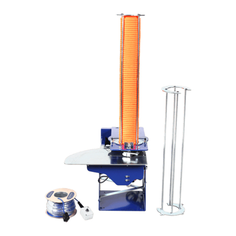
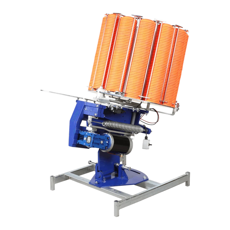
Promatic Hunter Wobble Installation manual

Serving the Clay Shooting Industry
Since 1985
Hunter Wobble
Game Trailer
Setup and Operating Instructions
Failure to read and understand these instruc-
tions before using this Clay Target Launcher
can result in death, bodily injury or property
damage.
If you have any questions regarding setup or
operation after reading this manual, call
Promatic for assistance at 888.767.2529 be-
fore proceeding.

To Order Call:
1.888.767.2529Page 2
ALWAYS USE TRAV EL BO LT WHEN MO VING TRAILER
When moving the trailer, re-insert the travel bolt into the back trap.
The bolt secures the trap for travel and is required to
prevent damage to the unit.
Always remove the travel bolt be fore operation. Failure to do so will
result in damage to the unit.
Breaker Box - Side View
Controls power to the
trap and wobble motor.
The trap will not fire
when it has been dis-
armed and the switches
on this box are in the
“off” position (the red on
the switch is visible).
Breaker Box - Front View
Arms and disarms the
trap and controls vertical
and horizontal trap move-
ment.
Mounted Receiver
Receives si nals from the
wireless transmitter to
control the trap and flush
sequences.
Wireless Transmitter
Controls firin of the trap
and starts and stops the
flush sequence.
Uses (2) CR2016 coin cell
batteries.
CAUTI N
This is an automatic machine. Targets may be released at any time.
Failure to read and understand these instructions before using this ma-
chine can result in death, bodily injury or property damage.
Read these instructions completely to insure the traps are DISARMED
properly before loading targets or performing maintenance. If you have
any questions after reading this manu al, call Promatic for assistance.
Traps should be DISARMED when the unit is not in use.
Position your body and all body parts behind the unit (tongue end of
the trailer). Never stand in front of or to the sides of the unit.
SEE PAGE 3 F R INSTRUCTI NS T DISARM THE TRAPS

Page 3
Promatic, Inc. 888.767.2529
C NTR L B X PERATI N
Arms and disarms the traps and controls their vertical and hori-
zontal movements.
ALWAYS DISARM MACHINES AND DISC NNECT BATTERY
BEF RE MAKING ADJUSTMENTS.
Position your body and all body parts behind the unit. Never
approach from the front, stand in front or to the sides o f the
unit.
ARMING T GGLE
Controls the Throwing Arm
•
In the Arm/Load (down) position, a tar et loads onto the throw-
in plate and the arm is cocked, ready for release.
•
Use the ff and Disarm/Nudge positions to DISARM the trap.
IMP RTANT: T DISARM THE TRAP: Push the Armin To le to the
ff (center) position then on up to the Disarm Nudge (up) position.
Hold the to le until the tar et is thrown, then release it.
After the tar et is thrown the machine is disarmed (throwin arm is
pointin in the 8:00 clock position). The to le returns to the ff
(center) position after disarmin the trap.
TO FULLY DISARM THE TRAP, YOU SHOULD ALSO SET THE SWITCHES
ON TH E BREAKER BOX TO OFF (THE RED ON THE SWITCH IS VISIBLE).
Arming Toggle
Although not marked
with a label, the center
position of the Disarm
Nudge -Arm/Load toggle
is the OFF position.

Page 4
Promatic, Inc. 888.767.2529
TES T / FIRE TO GGLE
Push this toggle to fire a target from the machine.
NUDGE / RO TATIO N TOGGLE
Controls the rotation (side to side) movement of the trap.
•
In the Rotation (down) position, the trap will move in a con-
tinuous side-to-side motion.
•
To activate the movement, press the Test/Fire toggle once.
Movement starts and stops at random intervals and will stop
completely if the machine is left unattended for more than 30
seconds.
•
In the Off (middle) posit ion, t he trap is locked at t he current
side angle.
•
Push the toggle to the Nudge (up) position to slightly change
the position of the fixed position of the trap.
Nudge / Rotation
Toggle
Test / Fire Toggle

Page 5
Promatic, Inc. 888.767.2529
NUDGE / ELEVATIO N TOGGLE
Controls the elevation (up & down) movement of the trap.
•
In the Elevation (down) position, the trap will move in a con-
tinuous motion as indicated by the label (elevation controls up
& down motion; rotation controls side-to-side motion).
•
To activate the movement, press the Test/Fire toggle once.
Movement starts and stops at random intervals and will stop
completely if the machine is left unattended for more than 30
seconds.
•
In the Off (middle) posit ion, t he trap does not move in the indi-
cated direction.
•
Push the toggle to the Nudge position to slightly change the
fixed position of the trap.
Nudge / Elevation
Toggle

Page 6
Promatic, Inc. 888.767.2529
WIRELESS TRANSMITTER PERATI N
Before loading targets or performing maintenance, please ensure traps are DISARMED.
FIRE BUTT N
The fire button has 2 modes of operation
•
Normal Mode - Fires the trap
•
Flush Mode - Starts the 20 Bird Flush sequence
To determine which mode the transmitter is in,
push and hold the Fire button for 2 to 3 seconds
•
If the Trap fires wh en the button is pressed, the
Transmitter is in Normal Mode
•
If the Trap fires wh en the button is released, the
Transmitter is in Flush Mode.
To change from Normal Mode to Flush Mode
Push and hold the Fire button for 8 to 10 seconds or
until the Trap STOPS cyclin - then release the Fire
button
To change from Flush Mode to Normal Mode
Push and hold the Fire button for 8 to 10 seconds or
until the Trap STARTS cyclin - then release the Fire
button
TIP
To save birds, before chan in the
firin mode (normal or flush), set the
Disarm Nud e - Arm/Load To le to
the off position.

Page 7
Promatic, Inc. 888.767.2529
SETTING A 20 BIRD FLUSH
1. Put the Transmitter into Flush mode as detailed above.
2. Push and Hold the Fire button for 4 to 5 seconds. Release the Fire button.
3. After about 5 se conds, the 20 Bird Flush will start.
4. To cancel the 20 Bird Flush, push and hold the Fire button for 10 seconds.
WIRELESS TRANSMITTER PERATI N
Before loading targets or performing maintenance, please ensure traps are DISARMED.
R TATI N BUTT N
The Rotation button controls the side-to-side move-
ment of the trap.
•
Pushin the Rotation button causes the Rota-
tion motor to run briefly.
•
Holdin the Rotation Button for 5 seconds locks
the Rotation motor ON and the motor will run
continuously.
•
To turn off the Rotation motor, push the Rota-
tion button briefly.
ELEVATI N BU TT N
The Rotation button controls the up & down move-
ment of the trap.
•
Pushin the Elevation button causes the Eleva-
tion motor to run briefly.
•
Holdin the Elevation Button for 5 seconds locks
the Elev ation motor ON and the motor will run
continuously.
•
To turn off the Elevation motor, push the Eleva-
tion button briefly.

Page 8
Promatic, Inc. 888.767.2529
T CHANGE THE BATTERIES
•
Remove antenna from top of transmitter
•
Remove back screws
•
Locate and replace 2 CR2016 coin cell batteries
•
Replace back and antenna
WARRANTY
The Hunter Wobble is covered by a 3 year warranty to the ori inal
purchaser of the machine.
R UTINE MAINTENANCE
ALWAYS DISARM MACHINES AND DISC NNECT BATTERY
BEF RE MAKING ADJUSTMENTS.
Position your body and all body parts behind the unit. Never ap-
proach from the front, st and in front or to the sides of the unit.
Proper care and maintenance will reatly extend the life of your ma-
chine. We recommend the followin :
Daily
•
Dirt, dust and tar et debris should be cleaned off the machine.
Accumulations of debris will result in broken clays, more wear on
bushin and bearin s, less than optimum performance and
erodes the protective coatin on the machine causin rust to
form. A shop vacuum or blower works well for this task.
•
Check that the batteries are fully char ed. A dead or low battery
will result in premature motor and electrical components failure.
We recommend usin a di ital battery tester.
Two to Four Times a Year
The followin maintenance should be performed two to four times a
year, dependin on tar et volume:
•
Inspect the battery cables for loose or corroded connections.

Promatic, Inc. 888.767.2529
Page 9
•
Inspect the throwin strip for uneven wear. Uneven wear can re-
sult in broken tar ets and is an indication that the throwin plate
hei ht needs to be adjusted.
•
Inspect to le switch and fire button covers for tearin and dry
rot. Replace items as needed to prevent moisture from dama in
electrical components in the housin .
•
Inspect nuts and bolts to insure nothin is loosened or over-
ti htened.
•
Lubricate all movin parts with a dry lubricant (i.e. silicone).
•
Grease the rease certs inside the carousel. DO NOT OVER
GREASE. If over reased, the rease will run onto the carousel
plate and cause erratic tar ets.

Page 10
Promatic, Inc. 888.767.2529
NOTES

Promatic, Inc. 888.767.2529
Page 11
This page intentionally left blank.

SALES and SERVICE
For any questions or help re ardin the setup or
operation of this Promatic machine, please contact
Promatic directly on one of the numbers listed be-
low.
SALES & SERVICE: 888.767.2529
EMAIL: Info@promatic.biz
ADDRESS: Promatic, Inc.
7803 West Hwy 116
Gower, MO 64454
WEBSITE: www.promatic.biz
Serving the Clay Shooting Industry
Since 1985
Table of contents
Other Promatic Accessories manuals


