Promatic Super Hawk User manual

You must treat a clay target launcher with the same cauon that you
would treat a loaded gun.
Assume at all mes that a clay target launcher is
armed and loaded and treat it accordingly
Operang Instrucons
Wobble units - Super Hawk
This document must be read in full before aempng to operate the machine
WARNING
Clay target launchers can be
dangerous and must be treated
with great care at all mes to
avoid accidents.
Never place any bodily part into
the path of any mechanical piece
whilst the machine is in moon or
likely to be so.

2
12v DC Power Source:
This product is designed to be powered from a 12v DC baery, it
SHOULD NOT BE DIRECTLY CONNECTED TO HOUSEHOLD AC POWER
Baery: Where a trap is connected to any other suitable power source
i.e. a Transformer - the relevant secons of instrucons should sll be
observed, i.e. “Disconnect the baery” and applied to this or any other
power source.
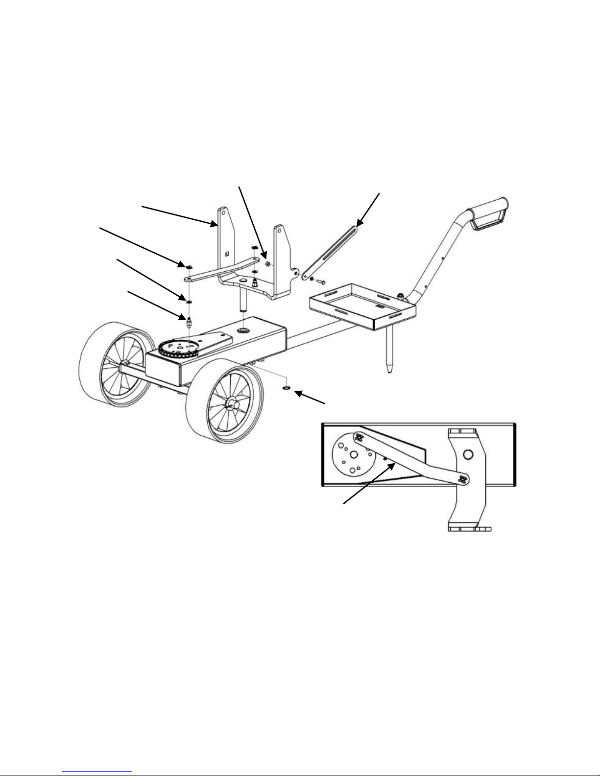
Extension
tube &
baery tray
Trolley
handle
Ground Spike
assembly
Rotaon box
WARNING THE TRAP MUST BE MADE SAFE
BEFORE CONTINUING - SEE BACK PAGE
Dis-assemble the trap from its base
The rotaon box forms the basis of the trolley
spine. A swivel piece mounted to this acts as a
mount for the trap and replaces the trap’s ex-
isng base.
As supplied your trap will be ed to a pressed
steel base plate (with diagonal braces) it should
be removed from this base complete with its
rear support stay, this stay and some of the
exisng fasteners will be required to complete
this assembly.
Assemble the Rotaon box to the trolley base:
Fit the trolley axle to the front (gear wheel) end
of the rotaon box, t the bolts from below
with the nuts secured inside the rotaon box.
For each wheel t a brass washer before &
aer and secure in place using a split pin.
Fit the extension tube baery tray assembly to
the rear end of the rotaon box, followed by
the trolley handle using the ground spike and
clam-plate assembly to complete the joint as
shown below.
Trolley
axle
3
Fit Trap mount & connect linkage to rotaon wheel:
(All versions)
Insert the trap mount’s lower pin through the bearing in the rotaon box as shown
below, secure with the circlip provided. Fit a threaded spigot to the trap mount, then
t a lightly greased washer, aach the short end of the linkage as shown below and
secure with a spring clip which simply slides into the ne groove, snapping in place
over the end of the sha.
Fit the other threaded spigot into any of the holes of the rotang wheel, t another
lightly greased washer to this spigot and connect the other end of the linkage with a
spring clip as before.
Mount the trap onto the base:
The trap should now be mounted onto the trap carrier. Use a nylock nut and washer on
the pivot points, ghten these unl the trap can just pivot freely on the base without
any resistance being felt.
Rear support stay:
If a rotaon box only is ed (DTL trap) the rear support stay (removed from the old
trap base) should be ed to the trap mount using the original bolt & washer as shown
above. Note this is xed into the hexagonal hole in the trap carrier using the locking
nut “backwards” i.e. the hexagon is placed into the hole and the bolt ed through it
so that the ange is on the inside of the trap carrier locking the assembly in place.
If an elevaon box is to be ed (ABT trap) the rear support stay should not be ed as
this could allow the frame to become locked causing damage to the elevaon motor or
linkage.
Circlip
Trap mount Rear support stay
Clip
Washer
Threaded
Spigot
Circlip
Trap mount
Rear support stay
Clip
Washer
Threaded
Spigot
Inverted anged nut
Note orientaon of linkage
4
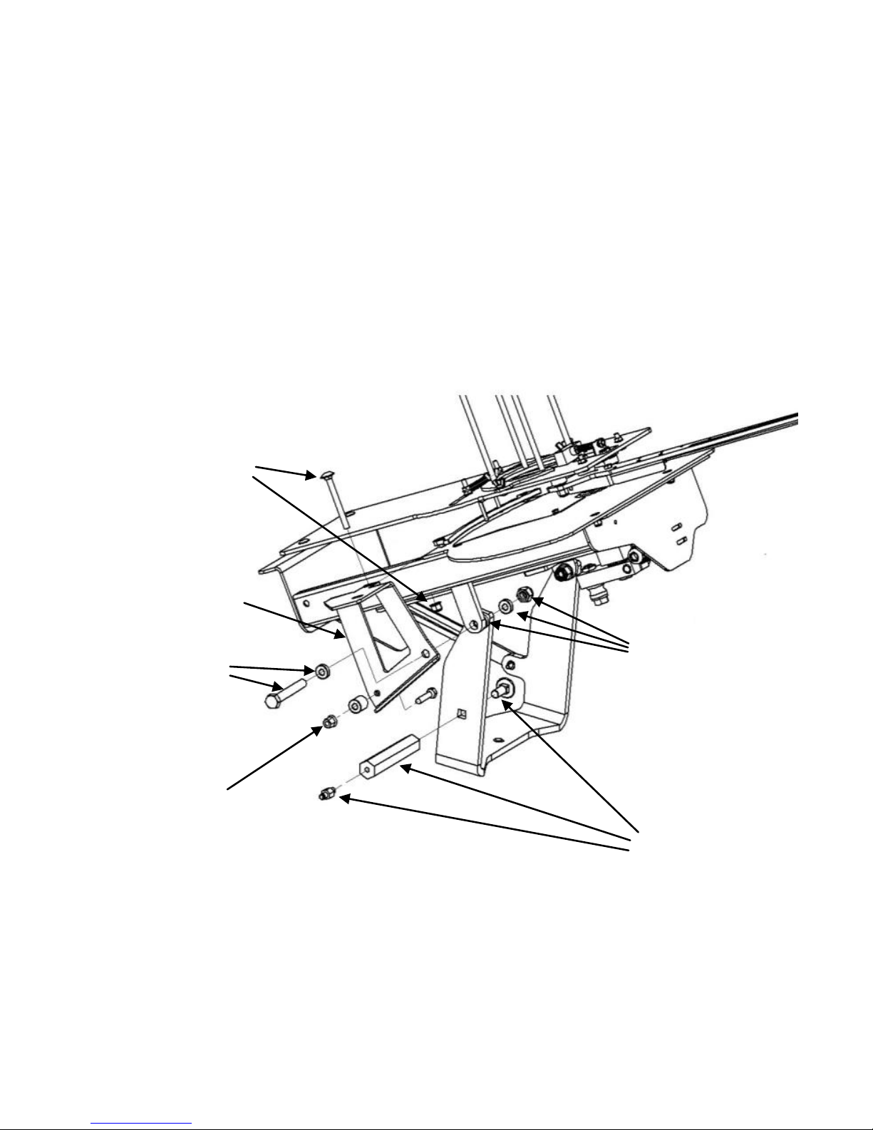
B
D
C
A
Elevaon box
mounng bracket
B
Assemble the Elevaon box and bracket (Where ed)
Insert the short M12 cup square bolt into the mounng hole in the side of the swivel
bracket and t the long hexagonal stud onto it (A on diagram) ghtening this securely
to the frame member, next insert a threaded spigot into the other end and ghten this
in place.
Aach the elevaon box mounng bracket to the trap’s right hand pivot point using
the longer M12 hex head bolt and 3 washers (B on diagram) lightly grease the centre
washer (between trap pivot and mount, then secure this assembly on the inside with
an M12 Nyloc nut. Similarly secure the trap’s le hand pivot point using the shorter
M12 hex head bolt and 3 washers, again apply grease to the centre washer and secure
with an M12 Nyloc nut. Do not over-ghten as these are the main pivot points.
Fix the bracket to the trap frame using the Long Cup square bolt vercally through trap
frame (C on diagram) secure below with an M8 nyloc nut.
At the rear of the bracket loosely place the M8x40 Cup square bolt and the shorter
nylon spacer (D on diagram) but do not t the nut yet.
Check that the trap pivots freely on its mount without any resistance being felt (too
much resistance would cause premature wear to the elevaon components as well as
excessive baery drain.
Fit the Elevaon box to the bracket
Remove the large black plasc plugs from the ends of the elevaon box (taking care
not to dislodge the electrical wiring from the motor) this will allow a clear view of the
internal keyhole slots in the rear face of the box.
The elevaon box has two keyhole shaped slots in its rear face, however on this model
these are not used in the convenonal manner.
Fit the elevaon box to the bracket at the front by passing the M10 hex head bolt
through the forward keyhole slot and securing internally with a Nyloc nut (Do not fully
ghten yet).
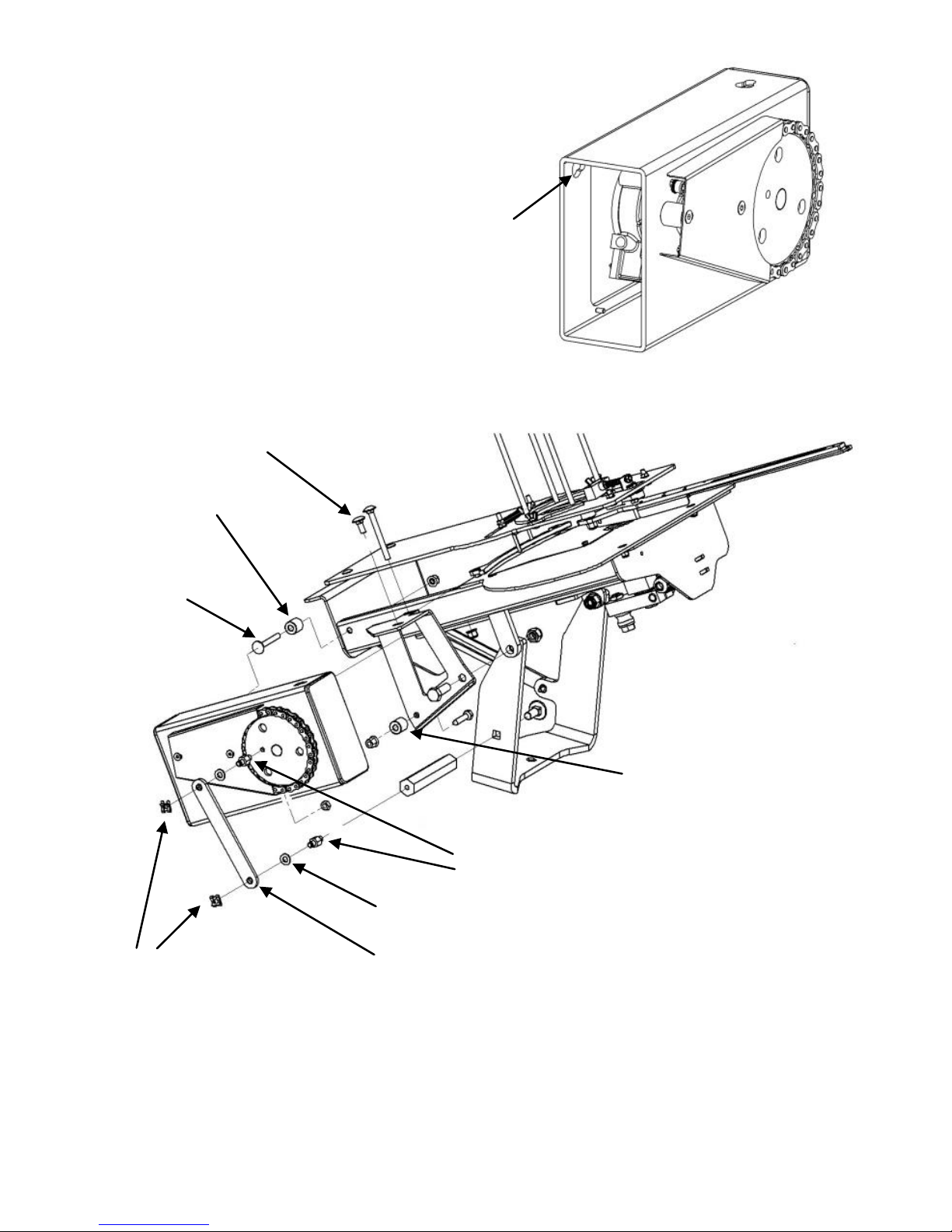
5
Each of the threaded spigots should now be ed with a lightly greased washer, fol-
lowed by the crank ed between them. The crank is secured by a spring clip at each
end which simply slides into the ne groove, snapping in place over the end of the
sha.
Keyhole
slot
At the rear of the trap pass the M8
cup square bolt through the rear key-
hole slot and the longer nylon spacer,
passing the bolt through into the hole
in the trap’s side frame ensuring that
the ats of the cup square head sit
properly within the thin part of the
keyhole slot before securing with a
Nyloc nut (Do not fully ghten yet).
Returning to the front of the elevaon
box, place the short M8 Cup square
bolt (Upper xing bolt on diagram
below) through the keyhole slot in the
upper face and securing internally
with a Nyloc nut.
At this stage all three nuts should be
fully ghtened and the plasc end
caps replaced.
Mounng
bolt
Nylon spacer
(Long)
Clip Crank
Threaded Spigots
Upper xing bolt
Washer
Nylon spacer
(Short)
6
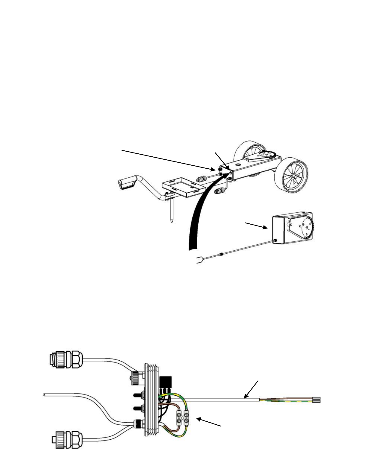
Elevaon
box
Blanking plug
Control panel
Connecng the electrical wiring:
Remove the black end plug (control panel) from the rotaon box.
The electrical assembly within the rotaon box has controls for rotaon and elevaon.
The elevaon box is connected into the exisng rotaon box, undo and discard the
white or light coloured blanking plug on the rotaon box and pass the wiring from the
elevaon box through into the rotaon box.
It is advisable to slacken the rear part of the gland to allow it to spin on the cable dur-
ing ng - this prevents the cable from twisng as the gland is screwed in.
Once the cable is in place ghten the gland into the threaded hole and t the plasc
nut to secure it in place, re-ghten the front part to seal the cable against moisture
ingress and prevent it pulling out in use.
The wiring for the elevaon unit is ed with metal boot-lace ends, and should be
ed into the terminal block connectors a shown below.
Elevaon box cable
Connecon to trap
Connector for
re buon Terminal block for elevaon
motor connecon
Rotaon motor
power cable
(ed)
Connect the wiring to the
terminal block.
The cable supplied will have
Brown and green/yellow wires
ed with metal boot-lace ends
(there may also be a blue wire cut
back—this is not used)
The brown wire should be connected to the terminal with the brown wire in it.
The green/yellow wire should be connected to the terminal with the green/yellow
wire in it.
Ensure that the screws are fully ghtened and that the gland is secure to prevent the
cable pulling out in use.
Replace the black end plug (control panel) in the end of the rotaon box ensuring that
the relays are passed inside the box and that no wires become trapped. Tap the plug
home with rm hand pressure near the edges.

7
Connect the baery:
Secure the baery to the tray using the Velcro strap(s) provided.
Ensure that the main power switch on the trap, as well as the two switches on the con-
trol panel are in the OFF (centre) posion before connecng to the baery.
The RED connector goes onto the + (or red coloured) baery terminal
The BLUE connector goes onto the - (or black coloured) baery terminal
How to operate:
Rotaon Funcon - Seng the switch down to the ROTATION posion will allow to
motor to run connuously varying the angle of the target le-to right. Pushing the
switch upwards to the NUDGE posion will give a momentary burst of movement for as
long as you connue to hold the switch toggle (automacally springing back to the OFF
posion when released) this will allow a xed trajectory to be selected.
Using the oponal holes on the rotaon disc a narrower or wider target eld can be
selected as desired.
The elevaon funcon (where ed) works in the same way, note that the pitch and
gearing of the two funcons has been designed so that the target movement in each
plane is not the same, and once the mechanisms have run for a few turns the move-
ment becomes unpredictable, making the targets that bit more challenging.
Refer to the main operang instrucons for details of specic features and operaon of
the trap, and the leaet provided with any radio which may have been purchased.
Motor wiring:
If any motor wiring has been supplied loose, or has been disconnected at any me
during trap assembly, reconnect as follows:
Warning:
THE TRAP MUST BE IN SAFE MODE BEFORE CONTINUING - SEE BACK
PAGE FOR INSTUCTIONS ON HOW TO DO THIS.

8
Promatic Inc.
801, Mid America drive
Plattsburg
MO 64477
USA.
Toll Free: 888.767.2529
Fax: 816.539.0257
E-mail: sales@promatic.biz
Website: www.promatic.biz
Promatic International Ltd.
Hooton Road
Hooton
South Wirral
CH66 7PA
United Kingdom
Tel: +44 (0) 151 327 2220 (General)
Fax: +44 (0) 151 3277075
E-mail info@promatic.co.uk
Website: www.promatic.co.uk
Super Hawk Wobble Version 1.6 March 2019
Safe Mode Procedure - Warning: Stand at rear of machine only
1. To disarm the machine press the red test fire button at the rear of the machine and
immediately push the on/off toggle switch upwards to the dis-arm position before the
machine re-arms.
2. Hold the toggle switch upwards until the throwing arm is pointing towards the front
of the machine.
3. Release the toggle switch and disconnect the baery/power source from the
machine .
Spring Removal / Tensioning:
Removal of, or tensioning of the spring can be carried out only in
the disarmed condition.
Table of contents
Other Promatic Accessories manuals


