PROMETHEUS SOLAR Plug & Play Solar Kits GT User manual

Powered By
Grid-Tied (GT) Roof-Mount
User Manual Rev. 2.1

2
Disclaimer of Liability
The use of this manual and the conditions or methods of installation, operation, use and
maintenance of the Plug & Play Grid-Tied (GT) is beyond the control of Prometheus Solar. Prometheus
Solar does not assume responsibility and expressly disclaims liability for loss, damage or expense,
whether direct, indirect, consequential or incidental, arising out of or anyway connected with such
installation, operation, use, or maintenance. Due to continuous improvements and product updates,
the images shown in this manual may not exactly match the unit purchased.
Contact Information
Prometheus Solar
11950 N US Hwy 89
Flagstaff, AZ 86004
Phone: 928.522.8103
Web: www.plugandplaysolarkits.com

3
CONTENTS
INTRODUCTION _ _ _ _ _ _ _ _ _ _ _ _ _ _ _ _ _ _ _ _ _ _ _ _ _ _ _ _ _ _ _ _ _ _ _ _ _ _ _ _ _ _ _ _ _ _ 4
SAFETY _ _ _ _ _ _ _ _ _ _ _ _ _ _ _ _ _ _ _ _ _ _ _ _ _ _ _ _ _ _ _ _ _ _ _ _ _ _ _ _ _ _ _ _ _ _ _ _ _ _ _ 4
THE PLUG&PLAY SOLAR KITS SYSTEM _ _ _ _ _ _ _ _ _ _ _ _ _ _ _ _ _ _ _ _ _ _ _ _ _ _ _ _ _ _ _ _ _ _ 6
INSTALLATION
Prior to Installation _ _ _ _ _ _ _ _ _ _ _ _ _ _ _ _ _ _ _ _ _ _ _ _ _ _ _ _ _ _ _ _ _ _ _ _ _ _ _ _ 7
Installing the Solar Panel(s) _ _ _ _ _ _ _ _ _ _ _ _ _ _ _ _ _ _ _ _ _ _ _ _ _ _ _ _ _ _ _ _ _ _ _ _ 8
Installing Add-On Solar Panel(s) _ _ _ _ _ _ _ _ _ _ _ _ _ _ _ _ _ _ _ _ _ _ _ _ _ _ _ _ _ _ _ _ _ 10
MONITOR SETUP
Linking Transmitter and Monitor _ _ _ _ _ _ _ _ _ _ _ _ _ _ _ _ _ _ _ _ _ _ _ _ _ _ _ _ _ _ _ _ _ 11
Setting the Time & Date _ _ _ _ _ _ _ _ _ _ _ _ _ _ _ _ _ _ _ _ _ _ _ _ _ _ _ _ _ _ _ _ _ _ _ _ _ 12
Setup Instructions _ _ _ _ _ _ _ _ _ _ _ _ _ _ _ _ _ _ _ _ _ _ _ _ _ _ _ _ _ _ _ _ _ _ _ _ _ _ _ _ _ 13
Instant Mode _ _ _ _ _ _ _ _ _ _ _ _ _ _ _ _ _ _ _ _ _ _ _ _ _ _ _ _ _ _ _ _ _ _ _ _ _ _ _ _ _ _ _ 15
History Mode _ _ _ _ _ _ _ _ _ _ _ _ _ _ _ _ _ _ _ _ _ _ _ _ _ _ _ _ _ _ _ _ _ _ _ _ _ _ _ _ _ _ _ 15
TROUBLESHOOTING TIPS
ELITE Wireless Electricity Monitor _ _ _ _ _ _ _ _ _ _ _ _ _ _ _ _ _ _ _ _ _ _ _ _ _ _ _ _ _ _ _ _ 16
Enphase M250 Microinverter _ _ _ _ _ _ _ _ _ _ _ _ _ _ _ _ _ _ _ _ _ _ _ _ _ _ _ _ _ _ _ _ _ _ 17
TECHNICAL INFORMATION _ _ _ _ _ _ _ _ _ _ _ _ _ _ _ _ _ _ _ _ _ _ _ _ _ _ _ _ _ _ _ _ _ _ _ _ _ _ _ 18
CUSTOMER SERVICE
Warranty _ _ _ _ _ _ _ _ _ _ _ _ _ _ _ _ _ _ _ _ _ _ _ _ _ _ _ _ _ _ _ _ _ _ _ _ _ _ _ _ _ _ _ _ _ 19
Consumer Support _ _ _ _ _ _ _ _ _ _ _ _ _ _ _ _ _ _ _ _ _ _ _ _ _ _ _ _ _ _ _ _ _ _ _ Back Cover

4
INTRODUCTION
The Plug and Play Solar Kits GT is a solar energy appliance that provides easy, affordable and
portable grid-tied or off-grid solar power to supplement your home or business energy needs through
the use of an outlet. The system can be as small as one solar panel or as large as the user desires,
simply by purchasing additional “Add-On” panels. The GT can be set up in almost any sunny spot and
can be moved to new locations easily, making it perfect for those who rent or intend to relocate.
Plug and Play has eliminated all the difficult, frustrating and confusing aspects of home solar! The
system is easy to install and there’s no need for professional installation.
IMPORTANT SAFTEY INFORMATION
Plug and Play Solar Kits makes every effort to make its products as safe and reliable as possible.
The goal is to have satisfied customers who enjoy their Plug and Play Solar kits for years to come.
However customers are required to read the following warnings and disclaimers pertaining to our
products and their use:
Plug and Play Solar kits are subject to all applicable local codes and the National Electric Code
(NEC), ANSI/NFPA 70. Check with your local permitting authority prior to performing any
electrical installations including the installation of your Plug and Play Solar kit. Additional
requirements for installing your Plug and Play Solar kit may be levied by your local permitting
authority. It is your responsibility to verify all code requirements with your local authority
prior to purchasing your Plug and Play Solar kit.
Plug and Play Solar kits are subject to all interconnection requirements levied by your local
electrical utility company. It is your responsibility to ensure your Plug and Play Solar kit meets
all requirements for interconnection prior to purchase. You must also verify the rules and
regulations in regards to net-metering agreements and excess power generation from your
Plug and Play Solar kit. Grid interactive solar devices such as the Plug and Play Solar kit that
are not pre-approved and/or inspected by your local utility may result in fines or even
permanent service disconnection from the electrical grid. Plug and Play Solar Kits assumes no
responsibility for fees, fines or electrical service interruption as a result of the interconnection
of your Plug and Play Solar kit.
Plug and Play Solar kits have been built as an appliance with the intended purpose of grid-tied
or off-grid solar energy production. Any use other than this voids all warranties and Plug and
Play Solar Kits accepts no responsibility for any adverse outcomes.

5
The outdoor outlet used to plug in the Plug and Play Solar kit(s) MUST be a dedicated outlet on
its own dedicated 15A or 20A circuit. This dedicated circuit and outlet should be installed by
qualified and/or licensed personnel only. No other loads or outlets are allowed on this
dedicated solar circuit! The maximum allowed for each outlet is six units which includes the
GT and five add-on units. For every six units purchased, an additional dedicated 15A or 20A
circuit and outdoor outlet must be used to accommodate the additional units.
Some GFCI(Ground-Fault Circuit Interrupter) outlets can be sensitive to the power produced by
the GT. To avoid nuisance GFCI tripping, it may be necessary to replace an existing GFCI outlet
with a standard 15A or 20A outlet.
Do not plug anything into your Plug and Play Solar kits other than additional Plug and Play
solar kits as described in the product Step by Step Set Up section of this manual.
Plug and Play Solar Kits GT units are not intended for installation on pitched roofs. Roof
mounting can be dangerous and difficult; Plug and Play solar accepts no responsibility for any
injuries sustained during installation. Plug and Play Solar Kits accepts no responsibility for any
damage to the unit or your property during the product installation.
Do not mount Plug and Play Solar kits to any other unstable structure. Plug and Play Solar kits
are intended for ground, flat-roof and deck use only. Mounting a Plug and Play Solar kits to
any other structure voids all Plug and Play Solar Kits warranties and Plug and Play Solar Kits
accepts no responsibility for any injuries or damage that occurs as a result of doing so.
Do not submerge any portion of the Plug and Play Solar Kits in water. All Plug and Play Solar
kits are intended for outdoor use and are created to withstand adverse weather
conditions. However no part of the Plug and Play Solar kit is intended for submersion in water.
Please monitor your Plug and Play Solar kit during wet weather to ensure that no part of the
unit is submerged in standing water, especially all power cords. Complete submersion in water
voids all warranties.
Any mechanical or electrical modifications to the Plug and Play solar unit(s) voids all
warranties.
Do not attempt to move a Plug and Play Solar kit unless you are physically able to do so. Plug
and Play Solar kits are made of high quality materials that can be heavy and awkward to move.
Plug and Play Solar Kits accepts no responsibility for any injury sustained while working with or
moving the unit(s).

6
THE PLUG&PLAY SOLAR KIT SYSTEM
The Plug and Play Solar Kits GT is the first solar product of its kind to combine interactive
features and simplicity of use. Each unit arrives fully assembled and only needs to be plugged into a
dedicated outdoor outlet in order to start producing solar power! Once it’s plugged in, the user can
truly “play” with the GT by using the interactive wireless meter to help find ideal placement and tilt-
angles.
Each lead unit comes with a wireless meter that has three displays. The displays show:
1. Kilowatts generated
2. Amount of carbon dioxide reduced
3. Average dollars saved.
This innovative interactive feature makes it easy for the user to adjust the placement and tilt-angle of
the panel to find the optimum output for the panel(s) – something that is not possible with traditional
rooftop solar.
The Plug and Play Solar GT is similar to any other appliance that plugs into a standard household
120Vac outlet. The only difference is that the unit produces power instead of consuming it! When
plugged in, a single unit will provide up to 240 Watts to anything currently using power within your
house. For example, if the house is consuming a total of 1,000 Watts of power, the GT will provide up
to 240 Watts of that power, reducing your electricity from the utility company to only 760 Watts. The
GT therefore slows your meter and reduces your electricity bill. In some conditions, it may be possible
for the GT unit to provide enough power to stop your meter or even spin your meter backward! In
this case, you can consult your local utility about selling power back to the utility company or receiving
credits on the power you’ve produced. This is often called “net-metering.” In order to net-meter, you
may need to have your utility’s approval prior to connecting your GT unit.
The GT is perfectly safe when unplugged from the dedicated outlet. The unit is designed to
immediately shut down when unplugged.
All electrical components contained within the GT unit are individually UL listed. The unit as a
whole is not UL listed.
The GT, when installed in an ideal shade-free area in Arizona, will produce an average of 1.2
kWh’s a day, or 438 kWh’s per year. This is enough energy to offset a large capacity
refrigerator or five 20-Watt light bulbs for 12 hours per day.
Up to six GT units can be connected together on one 15A or 20A dedicated outdoor outlet.
Consult Plug and Play Solar Kit's technical support if you would like to use more than six units.

7
INSTALLATION
PRIOR TO INSTALLATION
IMPORTANT NOTE: PLEASE DO NOT PLUG THE UNIT INTO OUTLET UNTIL SET UP IS COMPLETE!
Upon delivery: Each Plug and Play Kits GT unit is packaged securely in recyclable materials and
shipped via FedEx. It is important to visually inspect each unit upon arrival. Please examine each box
for any visible damage while the FedEx driver is still present. In the case of visible damage, you’ll need
to report it right away to the FedEx driver. Although damage is rare, all boxes must be opened and the
product inspected within 24 hours of delivery, so please check it out right away! Should there be any
hidden damage from shipping, Plug and Play Solar Kits must be notified within 24 hours by email so
that we can make a claim with FedEx and have a replacement unit on its way as quickly as possible.
PLEASE NOTE. WE WILL NEED PHOTOS OF THE DAMAGE TO COMPLETE THE CLAIM!
Items Required For Installation:
7/16 Combination Wrench
7/16 Ratchet Wrench
Utility Knife
Drill with Phillips Driver

8
INSTALLING THE SOLAR PANEL(S)
PLEASE READ THROUGH ALL THE DIRECTIONS BEFORE PROCEEDING WITH STEP 1.
1. Selecting a location on your roof. The ideal location is a flat surface, free of shade, as close as
possible to a dedicated outdoor outlet.
NOTE: It is highly recommended that you perform these setup instructions with two people.
2. Remove the unit from the box and remove all packing
materials.
3. Place the unit(s) on the ground. Lay the unit glass-side
down being very careful not to damage the glass.
4. Find the bolts which attach the “Z” brackets to the base
of the unit. The unit is shipped with the legs attached to the
base in the “shipping” position. (See Figure 1).
5. Loosen the bolts and rotate the “Z” brackets so that flaps
are facing out andtighten them. (See Figures 2)
Shipping
Location
F
igure 1
Installation
L
ocation
F
igure 2
9
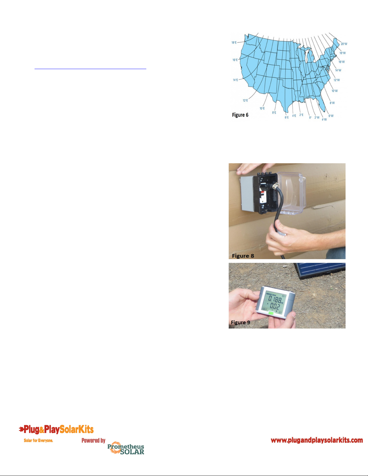
7. Point the front true south, as this direction provides the
most sunlight during the day. If you need information on how to
find true south for your location please visit
http://www.solaripedia.com/files/447 and use the chart
provided below.(See Figure 6)
8. Insert the provided ¼” by 2” lag bolts through the pre
drilled holes in the Z bracket and attach to the roof
trusses.(Optional – you can pre-drill the bolt locations with a
1/8”- 3/16” drill bit)
9. Remove the zip ties on the 30' cord and plug the GT into a
dedicated outdoor weatherproof outlet like the one shown
below. (See Figure 8) WARNING! Ensure there are no other
electrical loads connected to the circuit your GT is plugged into.
Connecting loads to this circuit may result in fire or damage to
the circuit. Refer to the “IMPORTANT SAFETY INFORMATION” in
this manual for more details.
10. After an NEC required five minute wait period, your GT
will sync with the utility grid and begin producing clean electricity
for your home. You can now use the included wireless monitor
to analyze the performance of your GT. (See Figure 9) Please
refer to the included ELITE Wireless Electricity Monitor quick
start guide for information on how to set up and use your
wireless monitor.

10
INSTALLING ADD-ON SOLAR PANEL(S)
WARNING! No more than five Add-On units can be added to your GT.
1. For each additional GT Add-On unit, follow steps 1-8 for
setting up the unit. Make sure to place each additional unit so
that it is in reach of the previously placed unit and does not cast
shade on any of the other units.
2. Once all units are set up, begin connecting the units
together. Remove the protective cap from your GT female
receiver plug. (See Figure 10)
3. Ensure the foam gasket is fully secured on the male plug
of the Add-On unit. (See Figure 11)
4. Plug the Add-On unit’s male plug into the GT unit’s
female connector. (See Figure 12)
5. Fasten the included green weatherproof cover around
each end of the connection and twist the bottom cover into the
top until it is fully seated. (See Figures 13&14)
6. Repeat steps 1-5 until all Add-On units are connected.
NOTE: Only the GT unit should be connected into the dedicated
outlet. Add-On units simply daisy chain to one another and
connect into your GT female connector.
NOTE: When installed correctly, the GT wireless meter will read
the total power produced from the GT and all Add-On units
connected to it.
11
MONITOR SETUP
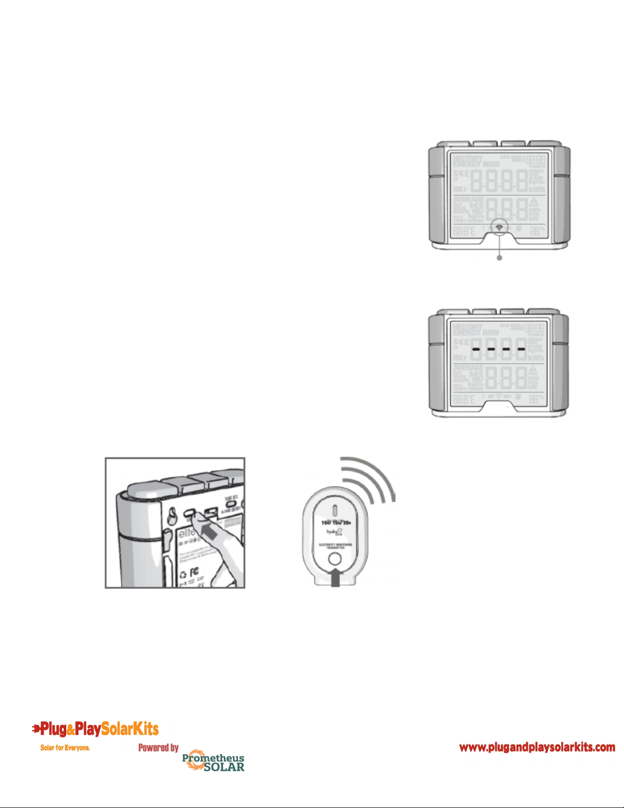
LINKING TRANSMITTER AND MONITOR
1. Ensure three AA batteries are inserted in the wireless
energy monitor. Observe polarity when inserting the batteries.
2. Press the link button on the back of the wireless energy
monitor and hold for two seconds. The transmission signal
symbol will flash for one minute or until the transmitter and
monitor are linked.
3. While the transmission signal symbol in the display
flashes, push the link button on the transmitter and wait until the
transmission signal symbol becomes solid.
Note: The default value for the transmission frequency is ten
seconds. This means the transmitter is sending information to
the display every ten seconds. You can change the frequency
from 10s to 15s or 20s by pushing and holding the transmitter
button for two seconds.
Potable display unit link button Transmitter link button
Transmission Signal Symbol
Dashes indicate signals not linked

12
SETTING THE TIME AND DATE
The elite monitor needs to know the time and date in order to
provide you with the correct information.
Set the time and date as follows:
1. On the reverse of the monitor you will find the time set
button. Press and hold for two seconds. The time setup will flash
on the monitor.
2. Set the hour to the correct time by using the backward
and forward buttons. Press the mode/set button once to save
the hours. Repeat for minutes, using the mode/set button to
confirm. Once the correct time and date have been set, push the
history button to save and move onto the date setup.
3. Set the month by using the backward and forward
buttons. Press the mode/set button to confirm and move onto
the day and year. Repeat the same process and then press the
mode/set button to save and exit.
Hold for 2 seconds

13
SETUP INSTRUCTIONS
The elite monitor needs to know unit cost per kWh charged by your electricity supplier, along with
voltage and alarm settings. The following steps will move through each of these settings.
Press and hold down mode/set button for three seconds to enter
the setting mode.
1 – Voltage
Press and hold mode/set button for two seconds. Default voltage
is set at 120V. Use backward and forward buttons to change the
voltage. Press mode/set button to save your setting and move
into currency selection setting.
2 - Currency Selection
Select the currency using backward and forward buttons. Default
currency will be “$”. Push mode/set button to confirm and to
move onto tariff selection set up.
3 - Single Tariff Set Up
On release you will see the 1 in the lower right hand corner of
the monitor. If you are charged one single tariff push mode/set
button to confirm.
4 - Electricity Cost
Default cost is set at 0.1$/kWh. Use backward and forward
buttons to change the cost per kWh. Press mode/set button to
save your setting.
14
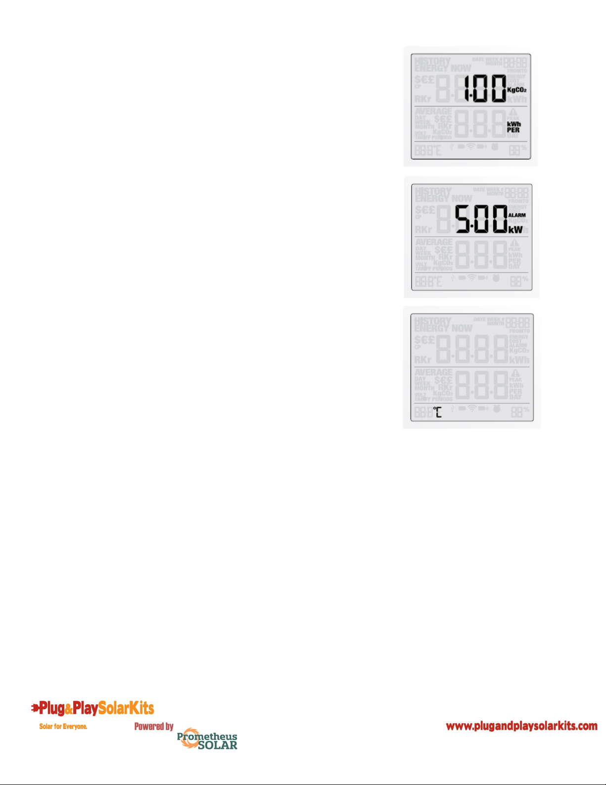
5 - Carbon Emissions Ratio
Now set your carbon emissions ratio. This value can be increased
or decreased using backward and forward buttons, press the
mode/set button to store the value. The North American average
is 1.04kg.CO2/kWh and is set as the default value.
6 - Alarm
Default alarm is set at 5kW. If the alarm function is switched on,
and you are using more than 5kW the alarm will sound and a red
light will glow from the bottom of the wireless energy monitor.
The value can be decreased or increased using the backward and
forward buttons. Press the mode/set button to store the value.
Press the history button to exit the function setting mode. To
activate and deactivate the alarm at any time push the alarm
button on the reverse of the wireless monitor.
7 – Temperature
The temperature setting can be changed between Fahrenheit and
Centigrade by pressing the backward and forward buttons.
Note: Throughout the setup process, push history button at any
time, your settings will be saved & you will exit the function
setting mode.
Note: Twenty seconds of inactivity in setting mode will return
the monitor to normal display mode without saving changes.

15
INSTANT MODE
Push the mode/set button to change information displayed from kW to cost (displayed in $).
HISTORY MODE
Push the history button to access daily, weekly, and monthly stored data. Use the backward and
forward buttons to scroll between dates and compare consumption data.
Press mode/ set button to change information from kWh to costs and Co2 emissions.

16
TROUBLESHOOTING TIPS
WIRELESS ELECTRONIC MONITOR
If I remove the batteries will I lose the information on the monitor?
The monitor has an internal memory, so if you need to change or remove the batteries and the
information stored on it will not be lost.
How do I reset the monitor (clear the stored data and start again)?
Press and hold the mode/set and history buttons simultaneously for two seconds.
How far does the device transmit?
The transmitter works up to around 230ft/40m within the home. The 433MHz range is well suited for
in-home use. This can cover three floors and is also ideal for buildings where electricity meters are
situated outside.
I have three dashes (- - -) showing on the monitor. What does this mean?
Move the monitor closer to the transmitter and press the link button. If the dashes remain on the
monitor this would indicate that the transmitter and receiver are not communicating. Please contact
our customer services to help solve the problem.
The backlight appears to work sometimes and then not others. Is it broken?
No. The backlight is on a timer to save battery life. The monitor should work at darker periods during
the day when any buttons are pressed. The LED backlight will be activated from 18:00 to 6:00 hours.
For more information about the elite go to www.efergy.us
M250 MICROINVERTER
Adhere to all the safety measures described throughout this manual.
WARNING: Do not attempt to repair the Enphase Microinverter; it contains no user-serviceable parts.
If it fails, contact Enphase customer service to obtain an RMA (return merchandise authorization)
number and start the replacement process.
STATUS LED INDICATIONS AND ERROR REPORTING
Startup LED Operation:
The status LED on the underside of each M250 lights green about six seconds after DC power is
applied. It remains lit solid for two minutes, followed by six green blinks. After that, red blinks indicate
that no grid is present if the system is not yet energized.
Six short red blinks after DC power is first applied to the microinverter indicate a failure during
microinverter startup.

17
Post-Startup LED Indications:
Use a handheld mirror to view indicator lights on the undersides of the microinverters:
Flashing Green: Indicates normal operation. The microinverter is receiving messages from the
Envoy and senses that the utility grid is within voltage/frequency specifications.
Flashing Orange: Indicates that the microinverter is not receiving messages from the Envoy, but
is otherwise operating normally. The microinverter senses that the utility grid is within
voltage/frequency specifications.
Flashing Red: Indicates that the microinverter is not operating normally. The microinverter
does not sense that the utility grid is within voltage/frequency specifications. The microinverter
cannot produce power until this is resolved.
Solid Red: DC resistance low fault. Troubleshoot as described in the following section.
DC Resistance Low Fault:
A solid red status LED when DC power has been cycled indicates the microinverter has detected a DC
Resistance Low event. The LED will remain red and the fault will continue to be reported by the Envoy
until the error has been cleared.
An Envoy is required to clear this condition. The condition usually clears with operator intervention
unless conditions causing the event have not been remedied or if the failure is permanent.
Follow the instructions in the Envoy Communications Gateway Installation and Operation Manual at
http://www.enphase.com/support to clear this condition. Or, for assistance, contact Enphase
customer support at [email protected].
Other Faults:
All other faults are reported to the Envoy. Refer to the Envoy Communications Gateway Installation
and Operation Manual at http://www.enphase.com/support for troubleshooting procedures.

18
TECHNICAL INFORMATION
Canadian Solar CS6P-265P PV Module
Operating Temperature: -40°C to~ +85°C
Cell Type: 60-cell poly-crystalline
Frame: Black anodized aluminum
Physical Dimensions: 64.5” x 38.7” x 1.57”
Compliance: IEC 61215, IEC 61730, UL1703, MCS, CE, CEC listed
Enphase M250 Microinverter
Max Continuous Output Power(AC): 240 Watts
Nominal Output Current: 1.0 A
Nominal Output Voltage(AC): 240 VAC
Operating Voltage Range(AC): 211-264 VAC
Nominal Frequency Range: 59.3 - 60.5 Hz
Peak Inverter Efficiency: 96.5%
CEC Weighted Inverter Efficiency: 96.5%
Operating Temperature: -40°C to +85°C
Compliance: UL 1741/IEEE 1547, FCC Part 15 Class B, CAN/CSA-C22.2
NO. 0-M91, 0.4-04, and 107.1-01
ELITE Wireless Electricity Monitor
Model Name/Number: EMWEMI
Frequency: 433MHz
Transmission Time: 10s. 15s. or 20s.
Transmission Range: 230ft – 328ft 40m – 70m
Voltage Range: 110V – 600V
Measuring Current: 50mA – 120A*
*Please note the CT sensor is compatible with 200A mains cables.
Carbon Ratio: 1.04 kg. CO2 / kWh
The LED backlight will be activated from 18:00Hrs to 6:00Hrs.
Transformer
Max Continuous Output Power(AC): 240 Watts
Nominal Output Voltage(AC): 120 VAC
Compliance: UL 506, CSA C22.2 No. 66, ROHS, Class B Insulation

19
CUSTOMER SERVICE
WARRANTY
25 year manufacturer's warranty on Module and Microinverter.*
10 year product warranty on parts and workmanship.*
*The above stated warranty does not apply to products which have failed due to improper
installation, misuse, alteration, unauthorized repair or modification, or acts of God.
Purchaser is responsible for transportation and handling costs of the equipment to and from
the distributor or dealer for warranty replacement or repair.
The above warranty does not include incidental or consequential damages and Prometheus Solar
disclaims any liability for any such damages. All implied warranties, if any, are limited in
duration to the above stated warranty period. Some states and provinces do not allow the
exclusion or limitation of incidental or consequential damages or a duration for an implied
warranty, so the above limitations may not apply to you. All liability is limited to the original
purchase price of the Module.

Designed and assembled in Flagstaff, Arizona
11950 N US Hwy 89 ~ Flagstaff, AZ 86004
1.800.347.2291
www.plugandplaysolarkits.com
Email your questions to:
info.usa@efergy.com for US
[email protected] for Canada
Email your technical questions to:
[email protected] for US
support@energymonitoring.ca for Canada
We aim to answer all your emails within 48 hours
www.efergy.us for US
www.energymonitoring.ca for Canada
1420 N. McDowell Blvd. Petaluma, CA 94954
http://www.enphase.com
info@enphaseenergy.com
support@enphaseenergy.com
Table of contents
Popular Solar Panel manuals by other brands


PowerTraveller
PowerTraveller EXTREME quick start guide

AEROCOMPACT
AEROCOMPACT CompactFLAT S05 Assembly instructions

Ezviz
Ezviz Solar Charging Panel-D manual

DAVIS
DAVIS EZ-Mount Solar Power Kit installation manual

Hypontech
Hypontech HMS-600W-C Quick installation guide

Laser
Laser SmartHome LSH-ODSLR-5W user manual