Promic UR-M256LC User manual

WIRELESS MICROPHONE SYSTE
M
USER'SMANUA
L
WIRELESS
MICROPHONE
SYSTEM
ENGLISH
ADD: Ningbo Free Trade Zone, WestArea.
Zhejiang, P.R.C
TEL: 86-574-86860690/0692/9743/9745
FAX: 86-574-86860689
E-mail: [email protected]
Http: //www.promic.cn
PROMICTECHNOLOGYCO.,LTD

CONTENTS
Table of Contents
1. Introduction
2. Important Safeguards
3. Parts Description
4. Specifications
5. Features &Frequency List
6. User's Guide
7. Connection
...............................................................................................................
.............................................................................................
...............................................................................
...................................................................................
......................................................................................
..............................................................................
.........................................................................................
...................................................................................................
................................................................
1
1
2~3
3
4~6
7~9
10
11
11
8. Trouble-shooting
9. Basic Set
TROUBLE SHOOTING &BASIC SET
9. Basic Set
(1) Receiver
(2) Antenna
(3) Transmitter
(4) 9V Battery
(5) Adapter
(6) 6.3 Signal Cable
(7) XLR Signal Cable
(8) User's Manual
1PC
2PCS
1PC
1PC
1PC
1PC
1PC
1PC
8.Trouble-shooting
11
Designs and specificationsare subject tochange without noticefor improvement.
Problem Solution
No sound
Noise or
interference
occurs
Distortion
Note: This system may beinterfered by radio wave.
Check receiver andmicrophone power.
Make sure transmitterand receiver frequencyis same.
Check if amplifieror other equipment'spower is on.Check if the
connection between receiverand mixer oramplifier is proper.
Check microphone batterypower.
Check receiver antennasconnection.
Check if receiveris too closeto metal partsor there is barrier
between transmitter andreceiver.
Make sure microphonebattery is installedfirmly and thereis no
interferential source.
Check if signalcable is wellconnected.
Check receiver antennasconnection.
When using 2or more microphoneset simultaneously, make
sure the frequenciesare not interferedeach other.
Check if theinterference comes fromother wireless microphone,
TV,radio and etc.
Check if amplifiervolume is toohigh or toosmall.
Check if theinterference comes fromother wireless microphone,
TV,radio and etc.
Optional parts:
Mounting rack 2PCS
High sensitivity cartridgeset

110
1. Introduction
IMPORTANT SAFEGUARDS
Thank you forchoosing our UHFsingle channel truediversity wireless microphonesystem.
Before use pleaseread this manualcarefully to understand the correct operationand have
the best results.It is aprofessional wireless microphonesystem designed forstage applications.
All the featurescompletely meet thestrict requirement ofprofessional users.
With excellent quality, affordable price,stable performance, andeasy to operate,UR-M256LC
is your bestchoice.
Use 6.3 unbalanced signal cableor 3 pinXLR balanced signal cable to connect
receiver AFOutput to MIC-INjack on mixer or amplifier.(Referto following illustration)
Before installation pleasemake sure receiverfrequency is same as transmitter
frequency.
AUDIO MIXER
LOUD SPEAKER LOUD SPEAKERAMPLIFIER
12
3456/7 8/9 10/11 LOUTPUTR
DC POWER
ADAPTOR
7. Connection
CONNECTION
2. Important Safeguards
Do not openthis product byyourself for adjustment.
When abnormity occurs,Please submit thisequipment to ourdealer for examination, adjus-
tment and repair.
One receiver cannotreceive signal fromtwo same frequencymicrophones simultaneously.
Other microphones withdifferent frequency orbrand cannot beused for thisreceiver.
Toreduce the riskof fire orelectric shock, do not remove thecover. High
voltage parts inside.
Do Not
Disassemble
Toreduce the riskof electric shock,do not touch power outlet whenit thunders,
do not pullpower plug withwet hands. Do Not
Touch
Toreduce the riskof fire orelectric shock from damaged power cord,do not
pull power cordfrom power outletstrongly. Always grasp theplug tightly then
pull it out.Turn offthe power ifthis equipment willnot be used for a longperiod
of time afterset-up.
Pull Out
AC Plug
To reduce the risk of electric shock, use only the specified power voltage. Forbidden
Toprevent damage fromdropping or inclining,do not put heavy articles onthe
top of thisequipment, do notplace this equipmenton shaking, inclining
unstable places. Forbidden
Toreduce the riskof electric shock,do not put vessel with liquidor small metal
parts on thetop of thisequipment, do notlet metal or flammable parts drop
into this equipment. Forbidden
Toreduce the riskof fire orelectric shock, do not expose thisequipment and
power cord tomoisture, dust andsun. Keep awayfrom hot apparatusor
places with oil,smoke and water. Forbidden
Keep power plugand outlet clean.Power plug andoutlet with accumulated
dust is aptto cause fire,clean them regularly. Insert powerplug into power
outlet entirely. Caution
When abnormity occurs,please pull outpower plug andcontact our dealer
when the followinghappens:
When smoke comesout from thisequipment and burningsmell can be smelt.
Water orother article goes into this equipment.
Drop on theground and unitis damaged. No sound output.
Power cord damaged.(Cord core exposesor cord broken)
FCC Caution :To assure continuedcompliance, any changesor modifications notexpressly
approved by theparty responsible forcompliance could voidthe user's authority to operate
this equipment. (Example- use onlyshielded interface cableswhen connecting to computer
or peripheral devices).
This device complieswith Part 15of the FCCRules. Operation is subject to thefollowing two
conditions:
(1) This devicemay not causeharmful interference, and (2) This device must accept any
interference received, includinginterference that maycause undesired operation.
Caution
29
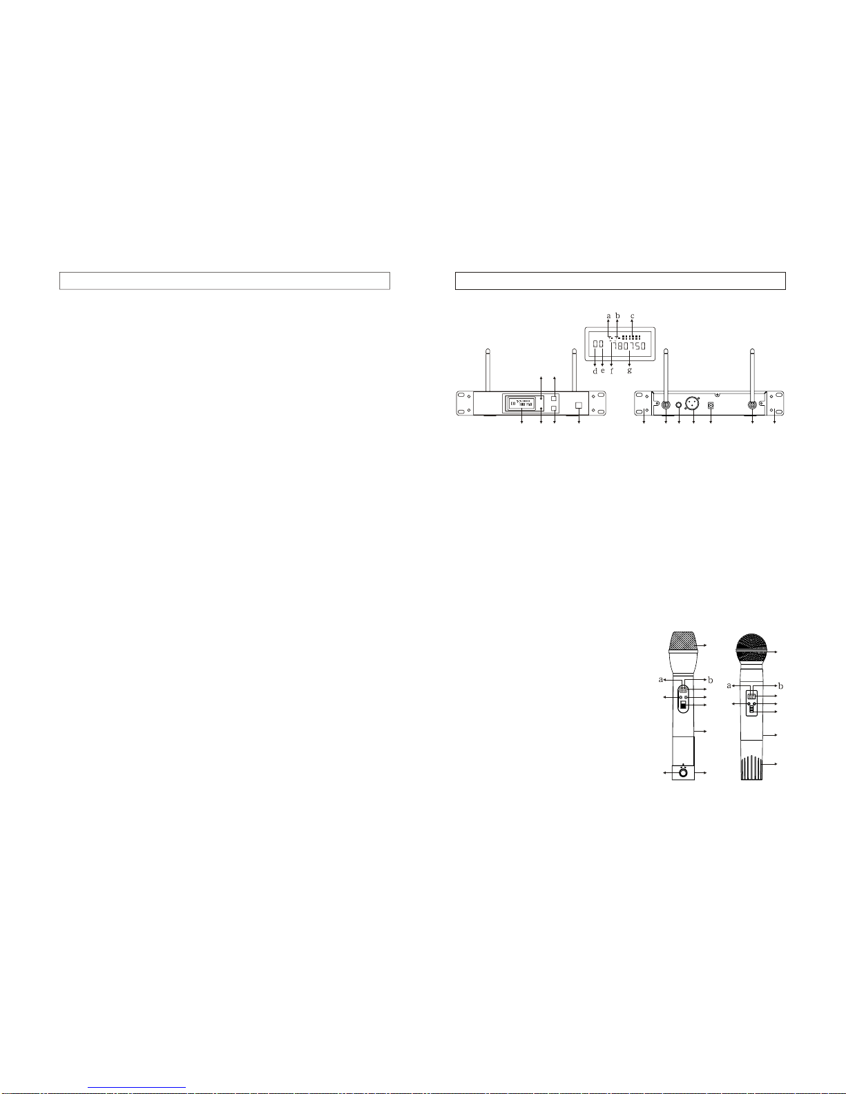
3.1 Receiver
3. Parts Description
3.2 Microphone
PARTS DESCRIPTION
(1) Power Switch
(2) GP: Groupset button andGP/CH adjust(UP).
(3) CH: Channelset button andGP/CH adjust(DOWN).
(4) GP LED indicator: pressGP button, it will light.
(5) CH LEDindicator: press CHbutton, it will light.
(6) LCD Display a. RF-Areception b. RF-Breception c. RFsignal strength indicator
d. GP number e. CHnumber f .AF signalstrength indicator g.Frequency
(7) Antenna B
(8) AFunbalanced output: phonejack.
(9) AFbalanced output: XLRjack, balanced AF signal outputsensitivity is sameas
dynamic microphone.
(10) DC PowerSource Input Jack:Connect AC/DC power supply
(11)Antenna A
(12) Mounting Rack
(Picture for referenceonly)
USER'S GUIDE
CH MHz
A B
,
AF
(8) (9) (10) (11) (12)(12) (7)(6) (1)
(2)
(3)
(4)
(5)
CH MHz
A B
,
AF
PUSH
OFF
(1) (1)
(2) (2)
(3) (3)
(4) (4)
(5) (5)
(6) (6)
(7)
(7)
(8)
(LCD Display)
(Front Panel) (Rear Panel)
A. Handheld Microphone
(1) Mesh &cartridge: Cartridge isprotected
by mesh toeliminate "POP" noise.
(2) CH LCDdisplay
a. GP number b. CHnumber
(3) GP: Groupset button andGP/CH adjust (UP).
(4) CH: Channelset button andGP/CH adjust
(DOWN).
(5) Power Switch
(6) Handheld microphonebody: Connect the
cartridge, mesh, andbattery compartment.
(7) Battery Compartment/ Cover: Forsetting
battery.
(8) Open Button:push to openbattery compartment.
4. Channel adjust:Press CH button(6) for about3 seconds, CHnumber on LCD
will flash; releaseCH button (6),press GP button to moveCH UP or CH buttonto
move CH down.
5. Afteradjusting Group andChannel, release allbuttons, group orchannel will flash
about 3 secondsand then stop,frequency will belocked and saved.
6. Adjusttransmitter's GP and CH (according to above procedure3, 4, 5) to make the
frequency same asreceiver.
7. After30 seconds ifno buttons arepressed, LCD willdisplay battery power.
Press GP button or CHbutton, LCD willshow GP number and CH number.
Note: If transmitter'sLCD shows"LO", itmeans battery powerwill be exhausted.
Please exchange newbattery. But the transmitterwill still work normally for
about 3 minutes.After 3 minutes if batteryis not replaced, transmitter will stop
working.
8. Insert attachedheadset or clip-onMIC into bodypack transmitter MIC-INjack. Use
attached screwdriver (3) to adjust GainControl (2) to have appropriate audiogain.

83
Figure 1 Figure 2 Figure 3
USER'S GUIDE
OPEN
LOCK
LOCK
OFF
LOCK
OFF
OPEN
PUSH
LOCK
PUSH
6.3 Body PackTransmitter
PARTS DESCRIPTION & SPECIFICATIONS
4. Specifications
25MHz
0.005%
-95dBm S/N 40dB
90dB
100mV 5mV
100dB
1%(AF=1KHz)
LCD
DC 12-15V
25MHz
0.005%
FM
55dB
25K
DC 9V
40mA
10mW
LCD
Frequency Bandwidth
Frequency Stability
Modulation
Spurious Emission
AF Modulation
Power Source
Current Consumption
Transmitting Power
Function Display Mode
Frequency Range
Oscillation Mode
Frequency Number
Frequency Response
Receiving Range
614MHz-806MHz
PLL synthesized
256
50Hz-20KHz
100m
Frequency Bandwidth
Frequency Stability
Sensitivity
Adjacent Channel Rejection
AF Output
SNR
Distortion
Function Display Mode
Power Source
4.1 General
4.2 Receiver
4.3 Transmitter
(1)
(3)
(2)
(4)
(5)
(6)
(7)
(8)
(9)
(TopView)
(LCD Display) (Front View)
B. Body PackTransmitter
(1) MIC-IN Jack
(2) Gain Control
(3) Small Screwdriver
(4) CH LCDdisplay
a. GP number b. CHnumber
(5) GP: Groupset button and
GP/CH adjust (UP).
(6) CH: Channelset button and
GP/CH adjust (DOWN).
(7) Power Switch
(8) Battery Compartment/ Cover:
Insert 9V battery.
(9) Antenna
4. Channel adjust:Press CH button(4)forabout 3 seconds,CH number onLCD will
flash; release CHbutton (4), pressGP button to move CHUP or CH button tomove
CH down.
5. Afteradjusting Group orChannel, release allbuttons, group orchannel will flash
about 3 secondsand then stop,frequency will belocked and saved.
6. Adjustmicrophone's GP and CH (according to above procedure3,4,5) to make the
frequency same asreceiver.
7. After30 seconds ifno buttons arepressed, LCD willdisplay battery power. Press
GP button or CH button,LCD will show GP number and CH number.
Note: If microphoneLCD shows "LO",it means batterypower will beexhausted.
Please exchange new battery.In the meanwhile, microphone will still work
normally for about 3 minutes. After 3 minutes if battery is not replaced,
microphone will stopworking.
8. Take out batteryif microphone is not going tobe used fora long periodof time.
9. Battery installation.
A. Turnbattery bottom cover90 degree anti-clockwiseto "OPEN" position(figure 1),
press "push" buttonto spring outbattery compartment alittle, pull outthe battery
compartment and installor exchange battery.
B. Insert 9Vbattery(pay attention tothe positive andnegative pole) andthen push
the battery compartmentback (figure 2).Turn batterycover 90 degreeclockwise
to "LOCK" position(figure 3).
1. Open batterycover(8), insert attached9V battery intobattery compartment and
then close battery cover.
2. Turnon power switch(7), LCD willshow group andchannel set atlast using time.
3. Group adjust:Press GP button(5) for about3 seconds, GPnumber on LCDwill
flash; release GPbutton (5), nowGP button changesto UP function and CHbutton
changes to DOWNfunction, press GPbutton to moveGP UPor CH buttonto move
GP down.

47
6. User's Guide
6.1 Receiver
USER'S GUIDE
1. Install attachedtwo BNC antennason the antennajack at therear panel of the
receiver. Inclineantennas outwards 45degree to getthe best reception.
2. To get thebest reception, install receiver at least1 metre abovethe ground. Keep
transmitter at least1 meter fromreceiver antennas andfar away frominterferential
sources.
3. Use attachedmounting rack toinstall receiver onEIA standardrack.
4.
5. AFoutput: Insert oneend of thesignal cable intoAF outputjack (8) or(9) at the
back of thereceiver and theother end ofthe signal cableinto amplifier ormixer
MIC-IN jack.
6. Turnon power switch(1), LCD will light and showthe group and channel number
set at lastusing time.
7. Press GPbutton (2), GPLED (4) willlight; release theGP button, GPLED will
extinguish. Press CHbutton(3), CH LEDindicator(5) will light;release the CH
button, CH LEDwill extinguish.
8. Group adjust:Press GP button(2) for about3 seconds, GPnumber on LCDwill
flash, frequency willalso flash; releaseGP button(2), nowGP button changesto
UP function andCH button changesto DOWN function,press GP button to move
GP UPor CH buttonto move GPdown.
9. Channel adjust: Press CH button(3) for about3 seconds, CH number on LCD
will flash, frequencywill also flash;release CH button(3),press GP button to move
CH UP or CH buttonto move CH down.
10. Afteradjusting Group andChannel, release all buttons, group orchannel will
flash about 3seconds and thenstop, frequency willbe locked andsaved.
11. Adjust receiverGP and CHto be same as transmitter GPand CH (
, receiver LCDwill showAF signal strength,RF signal
strength and RF Aor RF B reception.( These informationwill not showwhen
adjusting GP orCH, transmitter isnot turned on,or GP and CH oftransmitter is
different from receiver.)
Note: This system has 16sets of presetfrequencies (from 00to 0F) whichwill not
interfere each other. Users are suggested to usethese frequencies firstly.
Choose other frequenciesif more frequenciesare needed.
Plug one endof theAC power adapterinto ACpower source withspecified voltage
and the otherend into DCINPUT connector (10)on the backof receiver.
according to
the above procedure7,8,9)
6.2 Handheld Microphone
5. Features
1. UHF PLLsynthesized circuit, with256 selectable frequenciesfor choice.
2. Truediversity receiving modecan effectively avoid drop-outs anddead spots.
Available distance can bemore than 100 metre.
3.
4. Adopthigh stable circuitdesign and spareparts, this devicecan be operatedin
a wide rangeof temperature environment(-10 ~+60 ). AdvancedVCO circuit
design to allowperformers shout loudlywithout any brokenvoice happen. Itis the
best microphone systemfor stage performance.
5. Using highsensitivity, wide frequency response dynamic cartridge andadvanced
signal processing circuitto present thereal and natural voice of bothmale and
female. It isthe top choicefor live-performance singers.
6.
7. High performancecartridge. Following isfrequency response figure.
With special anti-interferencecircuit and tonecode security toeffectively avoid
interference and eliminatenoise.
Numeric LCD is clear and accuratein displaying receiving channel, receiving
signal level andAF signalstrength.
8. International EIAstandard half Urack. Metal case.Strong and nice.
9. Pre-programmed 16groups of frequencyto be usedsimultaneously without any
interference, including 00,01,02,03,04,05,06,07,08,09,0A,0B,0C,0D,0E,0F.
10. Pre-set twogroups of frequenciesfor choice. Oneis for USAstandard, another
is for Europestandard. Following isfrequency list.
X:1000Hz Y:-59.3dBV/Pa
Y:-57.1dBm/Pa
D:0.0dB
Y:-84.3dBV/Pa
Y:-82.1dBm/Pa
D:0.0dB
Z:-25.0dB
Microphone Frequency Response dB Ref.1V/Pa
FEATURES
-50
-60
-70
-80
-90
-100
20 50 100 200 500 1K 2K 5K 10K 20K
0 Deg
0Deg
180 Deg
180Deg
1. Open batterycover then insertbattery (pay attention to the positiveand negative
pole). Close batterycover(please see followingillustration for battery installation).
2. Turnon power switch(5), LCD willshow group andchannel set atlast using time.
3. Group adjust:Press GP button(3) for about3 seconds, GPnumber on LCDwill
flash; release GPbutton (3), nowGP button changesto UP function and CHbutton
(4) changes toDOWN function, press GP button to move GP UPor CH button
to move GPdown.

5
FREQUENCY LISTFREQUENCY LIST
USA STANDARD
805.850
792.650
791.150
801.550
799.950
788.850
782.050
804.350
799.850
789.250
805.150
797.350
787.150
798.550
801.650
781.550
804.150
789.750
794.050
781.050
794.650
782.550
783.350
801.050
800.650
790.750
800.250
793.350
783.850
795.150
785.450
782.950
802.250
791.350
786.850
803.250
794.350
790.450
791.750
799.550
802.050
784.950
784.150
798.250
795.350
790.050
804.850
803.650
800.350
795.950
790.950
805.450
786.550
785.150
802.950
804.650
787.550
782.250
794.850
780.550
788.150
796.150
798.850
785.950
798.650
795.550
787.750
799.350
780.850
796.750
796.450
781.850
781.350
799.150
786.350
783.650
793.550
801.850
787.350
782.750
796.550
780.150
784.750
800.450
797.950
802.750
791.950
803.050
792.450
801.150
800.850
792.250
801.750
792.950
783.150
797.150
794.750
789.850
795.050
796.050
787.950
802.550
804.150
785.750
796.950
800.050
799.050
788.450
789.050
784.550
793.450
789.550
792.850
794.450
792.750
798.350
790.350
798.050
784.450
782.350
803.350
805.050
802.350
790.150
805.350
790.650
786.250
785.550
791.050
801.450
788.750
788.250
799.750
781.650
782.650
787.450
784.250
791.450
786.950
792.050
800.750
793.050
780.650
794.150
789.650
786.050
785.050
784.350
796.650
793.650
789.450
795.450
780.250
800.550
783.450
798.650
795.850
783.050
781.950
798.450
787.850
783.750
786.650
793.150
793.250
796.250
803.550
803.950
797.550
792.550
791.650
784.850
804.750
794.950
797.850
801.950
786.450
791.550
798.150
796.850
791.250
785.350
795.250
793.750
804.550
797.050
797.250
792.350
789.950
781.250
788.050
804.250
784.650
780.950
788.350
803.450
795.650
787.650
786.150
803.750
794.550
798.750
789.350
799.650
802.650
780.350
790.550
785.850
783.250
791.850
790.850
793.950
797.750
805.250
789.150
784.050
799.250
788.550
781.750
787.250
785.250
796.350
782.850
782.150
781.450
781.150
783.550
802.850
800.150
804.950
798.950
788.650
801.250
805.550
786.750
780.450
804.450
794.250
800.950
802.150
780.050
780.750
782.450
783.950
785.650
787.050
788.950
790.250
792.150
804.050
803.150
801.350
799.450
797.650
795.750
793.850
EUROPE STANDARD
6
CH
GP 0123456789
0
1
2
3
4
5
6
7
8
9
A
B
C
D
E
F
851.050
851.700
852.150
852.950
851.400
852.050
853.950
854.350
853.650
851.250
852.550
852.300
853.250
855.600
853.450
857.250
851.950
851.850
853.100
853.800
858.050
855.050
856.350
856.000
862.900
854.950
855.300
857.750
854.850
855.800
856.650
857.500
852.650
854.700
857.100
851.550
858.700
856.800
858.400
859.550
859.100
860.500
860.100
852.800
859.800
854.150
858.900
852.900
853.550
856.150
861.000
863.600
859.300
853.350
860.750
862.200
863.400
855.450
860.300
861.800
863.100
858.250
862.000
856.500
854.250
861.600
852.400
857.850
861.200
854.500
862.550
863.300
854.050
857.350
860.600
862.750
863.800
859.450
856.250
855.250
855.150
862.400
859.650
863.200
851.500
856.600
858.150
860.900
861.300
861.900
863.700
856.750
851.150
855.700
857.600
855.900
855.850
859.200
863.500
856.100
859.950
854.600
856.450
857.950
851.350
858.800
860.200
852.500
859.750
861.100
861.700
856.900
856.950
858.500
857.200
859.400
860.400
862.300
862.100
859.900
860.650
862.650
863.000
857.050
858.600
851.800
860.850
855.550
857.650
861.400
853.750
861.500
857.450
860.050
854.800
858.350
862.800
853.900
852.750
852.250
855.400
853.150
851.650
851.100
858.550
852.100
854.450
853.000
858.200
851.200
858.750
862.700
859.050
854.200
855.750
862.500
860.450
854.650
859.600
852.450
859.250
857.800
861.150
860.250
855.000
858.000
862.250
861.550
852.000
856.200
863.450
853.500
863.250
853.300
852.700
863.650
860.150
857.300
854.000
861.050
855.950
862.350
858.850
859.000
852.200
856.300
861.350
860.800
856.550
861.750
854.400
860.950
861.850
860.700
862.950
863.750
854.900
856.850
859.350
851.600
853.600
854.300
859.700
862.050
855.200
858.300
857.550
853.050
863.050
861.950
857.900
862.850
863.350
853.400
861.450
859.150
862.450
859.850
855.350
853.700
851.750
861.650
860.550
862.600
863.950
851.300
863.150
863.550
856.700
851.900
860.350
851.450
861.250
852.350
860.000
853.200
859.500
858.450
858.650
858.950
864.750
857.000
858.100
855.500
857.150
856.050
854.750
852.600
857.700
856.400
855.100
855.650
854.550
852.850
853.850
854.100
A B CDEF
Popular Microphone System manuals by other brands

Ibiza sound
Ibiza sound VHF2H instruction manual

Meridian
Meridian FT/FR-2W2D/2D-x installation instructions

LD
LD WIN42HUB user manual

Stageline
Stageline TXS-2402SET instruction manual

Studiomaster Professional
Studiomaster Professional BR 48 Series instruction manual

Grimm Audio
Grimm Audio MP1 Manual guide


