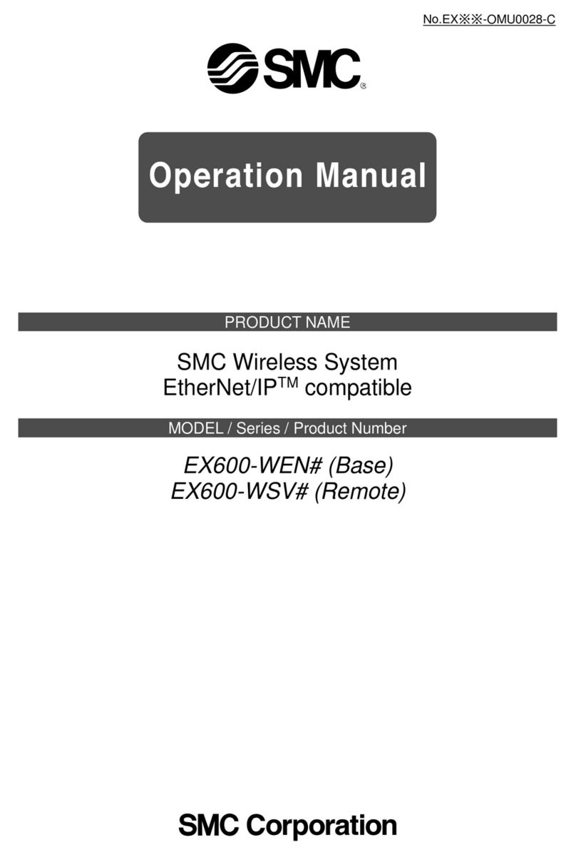
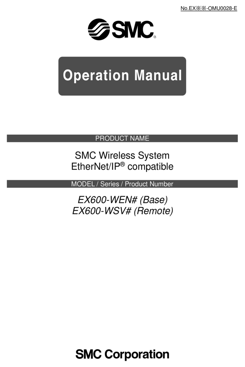
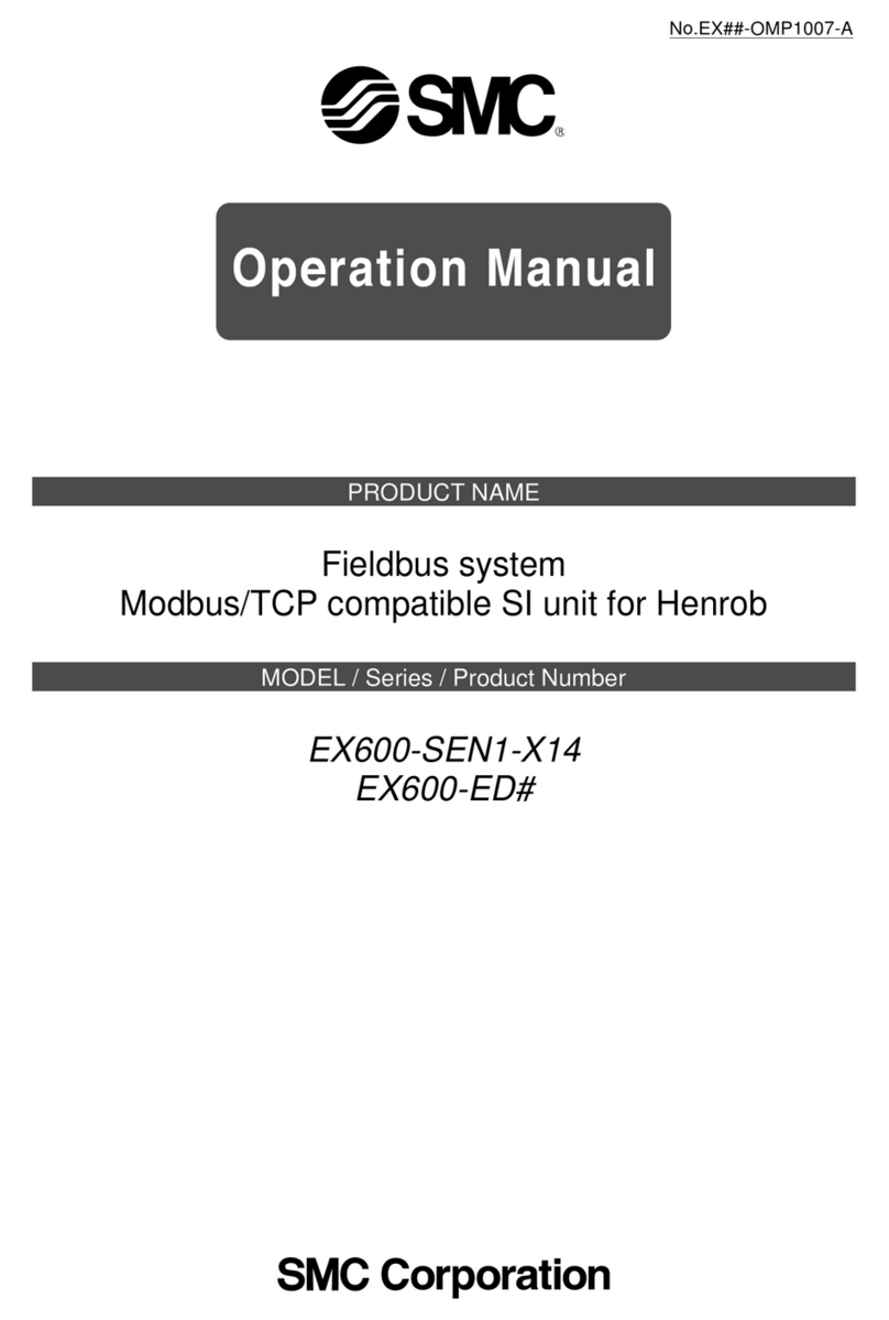
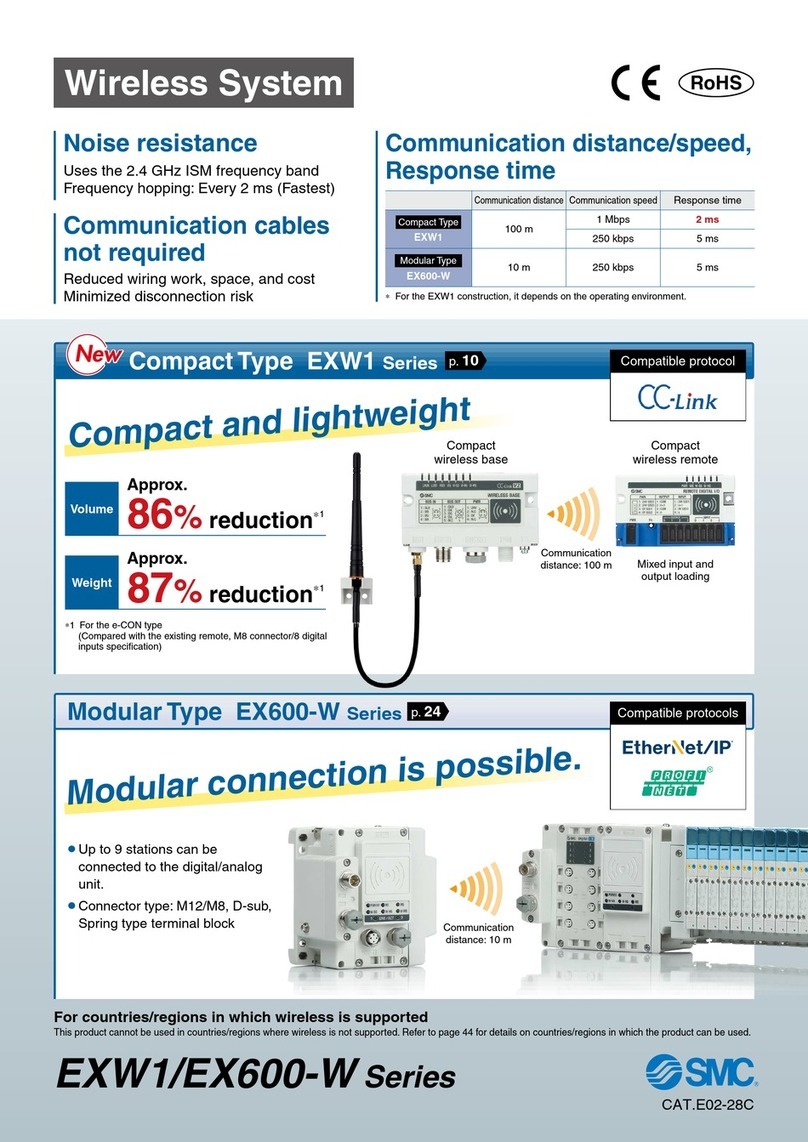
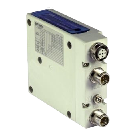
SMC Networks EX600-W Series User manual

Usable even in welding environments
Uses the 2.4 GHz ISM frequency band
Frequency hopping: Every 5 ms
Wireless communication signal
Response time: 5 ms
From power supply ON to start of
communication:
Min. 250 ms*1
High-speed connectionNoise resistance
Communication response
Reduced wiring work, space, and cost
Minimized disconnection risk
Max. 1280 inputs/1280 outputs
(Max. 128 inputs/128 outputs per module)
Compatible protocol
Number of I/O points
Communication cables not
required
Remote
Spot welding
Material
handling robot
Remote
Base
*1 For remote
Remote moduleBase module
Countries/Regions in which wireless is supported
This product cannot be used in countries where wireless is not
supported. Refer to page 23 for details on countries in which
the product can be used.
Country/Region Standards
Japan (Japanese radio law)
EU (CE marking/RE Directive)
USA (FCC)
New
RoHS
CAT.E02-28B
EX600-W Series
Wireless System
「
web-kigou
レイヤー」です。
※このレイヤーは、通常は隠しておく(
web
校了時のみ表示)
「
web-kigou
レイヤー」です。
※このレイヤーは、通常は隠しておく(
web
校了時のみ表示)
B

kHz MHz GHz
Wireless System
Wireless LAN
RFID
Bluetooth
AC/DC
welding machine
Motor driver/
Electromagnetic heater, etc.
10 10 101 1100 100
Communications using various forms of radio wave propagation
Wireless System EX600-W Series
Provide stable communication
Provide safe and reliable communication
Remote
Base
PLC
Power
supply
Noise in
electronic
circuits
Interference
from other
wireless
equipment
Reflected wave
Direct wave
Uses the 2.4 GHz ISM frequency band
Wireless
devices
Site
noise
*ISM (Industrial, Scientific and Medical) radio bands: Radio bands reserved for the use of radio frequency energy for industrial,
scientific and medical purposes.
Communication possible
in a 10 m radius
Transmitted wave
Automatic restoration
of communication
If the number of retries exceeds the stipulat-
ed value (32 times), a disconnection flag will
be output. The system will enter resync mode
and synchronization will be established. Once
completed, the normal operating conditions
will be restored, the disconnection flag will be
canceled, and control will resume.
1
「
web-kigou
レイヤー」です。
※このレイヤーは、通常は隠しておく(
web
校了時のみ表示)
「
web-kigou
レイヤー」です。
※このレイヤーは、通常は隠しておく(
web
校了時のみ表示)
A
Time
Frequency
5 ms
Actual communication time
Frequency of the radio wave interference
Communication frequency interference (for example, Wi-Fi)
Wireless System EX600-W Series
Base
Base
Remote
Unauthorized access/
data falsification
Unauthorized
wiretapping
Removing
device
Remote 1
Remote 2 Remote 3 Remote 4
Frequency hopping: Every
5
ms
A stable wireless environment is established using an original
protocol which is not affected by interference. Interference from other
wireless equipment is prevented.
Unauthorized access from outside is prevented by using
data encryption.
High security using encryption
Point-to-Multipoint communication
Registration and communication of up to 127 remote
modules is possible.
For remote
W-SS (Radio wave receiving intensity (For communication from base to remote))
Green LED is ON. Received power level is 3.
Green LED flashes. (1 Hz)
Received power level is 2.
Green LED flashes. (2 Hz)
Received power level is 1.
Red LED flashes.
Wireless communication is not connected.
OFF Base module is not registered.
<Communication status can be downloaded by a PC>
By connecting the base to a PC, it is possible to view log files which show the number of
retries or the received radio wave intensity. Log files are accessed by using a web browser to
connect to the built-in web server. The wireless environment and installation location can be
optimized by checking the number of retries and received radio wave intensity.
Frequency Hopping
The communication technology rapidly changes frequency (hopping), to
prevent interference from other wireless equipment. When the frequency of
Wi-Fi and other wireless communications compete, or radio wave interference
is present, then other frequencies are used for communication. For details,
refer to technical data on page 23.
*A received radio wave intensity level of 1 means the intensity is weak. Add
a base so that the wave intensity becomes level 3 or 2. Alternatively
remove the obstacle between the base and remote, or reduce the distance
between the base and remote.
The log files showing the number of retries
or the received radio wave intensity, can
be downloaded in the form of a CSV file.
Web screen example PC
*1 to 15 units are recommended for simultaneous operation.
*It is possible to install multiple bases in the same area.
For Base
W-SS (Radio wave receiving intensity (For communication from remote to base))
EtherNet/IP™
PROFINET
Green LED is ON.
Received power level of all remotes is 3.
Green LED flashes. (1 Hz)
There are connected remotes with
received power level 2.
Green LED flashes. (2 Hz)
There are connected remotes with
received power level 1.
Red LED flashes. No remotes connected.
OFF Remote module is not registered.
Wireless communication status can be monitored.
<Monitoring the remote communication status>
The wireless system connection can be monitored during operation
according to the diagnostic data.
The installation location can be ascertained according to the intensity
level of the radio wave received by the unit display.
[Diagnostic data]
*When communication from the remote cannot be received
*When communication retry has exceeded the upper limit (32 times)
[Unit display]
EtherNet/IP™
Max. 127 units
PROFINET
Max. 31 units
2
「
web-kigou
レイヤー」です。
※このレイヤーは、通常は隠しておく(
web
校了時のみ表示)
「
web-kigou
レイヤー」です。
※このレイヤーは、通常は隠しておく(
web
校了時のみ表示)
A
Wireless System EX600-W Series
2 units
Base
Wireless system Wired system
Remote 1 Remote 2 Remote 3
Power supply
Power
supply
Power
supply
1 unit1 unit 2 units 3 units …15 units
3 units …15 units
Communication line q
Connector
Power supply line
Power supply line Power supply line
Communication line
w
Communication line
w
SI unit
SI unitWireless unit
Current (Wired) SystemWireless System
Number of communication devices
Communication line Communication
connectors
required
qw
Wireless system Base: 1 unit
Remote: 15 units
1 line
(Connector at one end) — 1 place
Current (Wired) SI unit: 15 units 1 line
(Connector at one end)
14 lines
(Connector at both ends) 29 places
*Maximum I/O of base/remote
module is limited to 128 points.
Connection interchangeability between EX600 series SI units is maintained.
Replacement of wireless and wired systems is possible.
Wiring material cost and installation work-hours can be reduced.
Interchangeability maintained
Communication line q
PLCPLC
PC + Setting software
NFC reader/
writer
NFC
contactless communication
(NFC: Near Field Communication)
Configuration File
Settings are possible using an NFC reader/writer and setting software.
(Some items can be set even when there is no power supplied.)
¡Write IP address to the base
¡Set the I/O points for the system and unit
¡Pairing of the base and remote
¡I/O monitoring
SI unit: Comparison when
15 units are connected
Documents/Download
Instruction Manuals
Fieldbus System
Serial Transmission System
EtherNet/IP™ Compatible
or
PROFINET Compatible
I/O Configurator for NFC
From SMC website
Configuration File
3
「
web-kigou
レイヤー」です。
※このレイヤーは、通常は隠しておく(
web
校了時のみ表示)
「
web-kigou
レイヤー」です。
※このレイヤーは、通常は隠しておく(
web
校了時のみ表示)
B

Wireless System EX600-W Series
¡Minimized disconnection risk
¡ Smaller diameter communication
cable/tubing
Application Examples
Power supply
line only
Power supply lineCommunication line
Blocking of radio waves
Tool change
Rotary table
¡Communication cable is not necessary for moving parts.
¡Minimized disconnection risk
¡Shorter time for establishing communication (startup time)
*The radio waves must not be blocked by nearby conductive
objects such as metal enclosures or covers.
Wired system
4

Remote module No. 1 Remote module No. 3
Remote module No. 2
Solenoid valve
Solenoid valve EX600 I/O unit
EX600
I/O unit
p. 7 p. 7
p. 7
Combination Example wCombination Example e
Combination Example q
Wireless Network
Fieldbus
PLC
Wireless System EX600-W Series
Initial setting/monitoring/
pairing are possible.
Setting/Monitor tool
EX600 I/O unit Base module
Number of I/O points:
Max. 1280 inputs
1280 outputs
System Examples
Refer to the Web Catalog.p. 7
Other products
Pressure switch, flow switch, auto switch, and other switches
(proximate sensor, photoelectric switch, limit switch, etc.)
Various actuators
Applicable Manifold Solenoid Valves
SY Series SV Series S0700 Series
IP67 IP67 IP67IP40
®
VQC Series
PC
5
「
web-kigou
レイヤー」です。
※このレイヤーは、通常は隠しておく(
web
校了時のみ表示)
「
web-kigou
レイヤー」です。
※このレイヤーは、通常は隠しておく(
web
校了時のみ表示)
A
Accessories
qEnd Plate Bracket ················································· p. 18
wValve Plate ···························································· p. 18
eReinforcing Brace ················································· p. 18
rSeal Cap ······························································· p. 18
tMarker (1 sheet, 88 pcs.) ······································ p. 19
y
Communication Cable with Connector/
Communication Connector ··································· p. 19
u
Power Supply Cable with M12 Connector (A-coded)
······ p. 20
u
Power Supply Cable with M12 Connector (B-coded)
······ p. 21
iPower Supply Cable with 7/8 Inch Connector/
Power Supply Connector ······································ p. 22
Technical Data ············································································································································································ p. 23
Important ···················································································································································································· p. 23
Safety Instructions ···························································································································································· Back cover
How to Order
Wireless Unit ······························································· p. 7
Digital Input Unit ·························································· p. 7
Digital Output Unit ······················································· p. 7
Digital Input/Output Unit ·············································· p. 7
Analog Input Unit ························································ p. 8
Analog Output Unit ······················································ p. 8
Analog Input/Output Unit ············································· p. 8
End Plate (D side) ······················································· p. 8
End Plate (U side) ······················································· p. 8
Ordering Example of the Base Module ······················· p. 9
Ordering Example of the Remote Module ·················· p. 9
Specifications
Base Module ····························································· p. 10
Remote Module ························································· p. 12
End Plate (D side) ····················································· p. 12
Dimensions ································································· p. 13
LED Display ································································· p. 15
CONTENTS
Wireless System
EX600-W Series
Remote moduleBase module
6
「
web-kigou
レイヤー」です。
※このレイヤーは、通常は隠しておく(
web
校了時のみ表示)
「
web-kigou
レイヤー」です。
※このレイヤーは、通常は隠しておく(
web
校了時のみ表示)
A
Wireless System
EX600-W Series
How to Order
Protocol
Symbol
Specifications Note
EN Base module For EtherNet/IP™
PN Base module For PROFINET
SV Remote module —
Wireless compatible Output type
Symbol
Specifications
1PNP
2NPN
ENWEX600 1
Wireless Unit
*For specifications, refer to the Fieldbus
system EX600 series in the Web
Catalog.
*For specifications, refer to the Fieldbus
system EX600 series in the Web
Catalog.
*For specifications, refer to the Fieldbus
system EX600 series in the Web
Catalog.
DXEX600
DYEX600
DMEX600
Input type Number of inputs and Connector
Output type Number of outputs and Connector
Input/Output type Number of inputs/outputs and Connector
Symbol
Number of inputs
Number of outputs
Connector
E8 inputs 8 outputs
D-sub connector (25 pins)
F8 inputs 8 outputs
Spring type terminal block (32 pins)
Symbol
Description
PPNP
NNPN
Symbol
Number of outputs
Connector
B
8 outputs
M12 connector (5 pins) 4 pcs.
E
16 outputs
D-sub connector (25 pins)
F
16 outputs
Spring type terminal block (32 pins)
Symbol
Description
PPNP
NNPN
Symbol
Number of inputs
Connector
B8 inputs M12 connector (5 pins) 4 pcs.
C8 inputs M8 connector (3 pins) 8 pcs.
C1 8 inputs
M8 connector (3 pins) 8 pcs., With open-circuit detection
D16 inputs M12 connector (5 pins) 8 pcs.
E16 inputs D-sub connector (25 pins)
F16 inputs Spring type terminal block (32 pins)
Symbol
Description
PPNP
NNPN
P
P
P
D
B
F
Digital Input Unit
Digital Output Unit
Digital Input/Output Unit
Base module Remote
module
RoHS
7
「
web-kigou
レイヤー」です。
※このレイヤーは、通常は隠しておく(
web
校了時のみ表示)
「
web-kigou
レイヤー」です。
※このレイヤーは、通常は隠しておく(
web
校了時のみ表示)
A
For M12 For 7/8 inch
Wireless System EX600-W Series
How to Order
End plate
End plate mounting position: U side
E U 1EX600 2
Specifications
Symbol
Specifications
1Waterproof cover
End Plate (U side)
AXEX600
Analog input Number of input channels and Connector
Symbol
Number of input channels
Connector
A2 channels M12 connector (5 pins) 2 pcs.
A
Analog Input Unit
AYEX600
Analog output Number of output channels and Connector
AMEX600
Analog input/output Number of input/output channels and Connector
Symbol
Number of input channels Number of output channels
Connector
B2 channels 2 channels M12 connector (5 pins)
4 pcs.
Symbol
Number of output channels
Connector
A2 channels M12 connector (5 pins) 2 pcs.
A
B
Analog Output Unit
Analog Input/Output Unit
*For specifications, refer to the Fieldbus
system EX600 series in the Web
Catalog.
*For specifications, refer to the Fieldbus
system EX600 series in the Web
Catalog.
*For specifications, refer to the Fieldbus
system EX600 series in the Web
Catalog.
*1 The pin layout for “4” and “5” pin connector
is different.
Refer to the dimensions on page 14.
End plate
End plate mounting position: D side
E DEX600 2 2
Power supply connector
Symbol
Power supply connector
Specifications
2M12 (5 pins) B-coded IN
37/8 inch (5 pins) IN
4
M12 (4/5 pins) A-coded
*1IN/OUT
5
M12 (4/5 pins) A-coded
*1IN/OUT
Mounting method
Symbol
Description Note
Nil
Without DIN rail mounting bracket
—
2
With DIN rail mounting bracket
For SV, S0700, VQC series
3
With DIN rail mounting bracket
For SY series
*When the end plate (U side) is used, the symbol for the
mounting method must be the same as the D side.
End Plate (D side)
Mounting method
Symbol Description Note
Nil
Without DIN rail mounting bracket
—
2
With DIN rail mounting bracket
For EX600-ED-2
3
With DIN rail mounting bracket
For EX600-ED-3
*When the end plate (D side) is used, the symbol for the
mounting method must be the same as the U side.
8

U sideD side
12345
Valve stations
1
3
0
2
3
5
7
10
2
4
8
AB
B
12
A
14
AB
B
12
A
14
AB
B
12
A
14
AB
B
12
A
14
AB
B
12
A
14
Wireless unit
(Base module)
EX600-WEN1
Digital output unit
EX600-DYPB
Digital input unit
EX600-DXPD
End plate (D side)
EX600-ED4
2-position single
SY3100-5U1 (3 sets)
2-position double
SY3200-5U1 (2 sets)
D side U side
Wireless unit (Base module)
EX600-WEN1
End plate (D side)
EX600-ED4
End plate (U side)
EX600-EU1
1
3
0
2
3
5
7
10
2
4
8
D side U side
Wireless unit
(Remote module)
EX600-WSV1
End plate (D side)
EX600-ED4
End plate (U side)
EX600-EU1
Digital output unit
EX600-DYPB
Digital input unit
EX600-DXPD
U sideD side
12345
Valve stations
1
3
0
2
3
5
7
10
2
4
8
AB
B
12
A
14
AB
B
12
A
14
AB
B
12
A
14
AB
B
12
A
14
AB
B
12
A
14
2-position single
SY3100-5U1 (3 sets)
2-position double
SY3200-5U1 (2 sets)
Wireless unit
(Remote module)
EX600-WSV1
Digital output unit
EX600-DYPB
Digital input unit
EX600-DXPD
End plate (D side)
EX600-ED4
EX600-W Series
Ordering Example of the Base Module
Ordering Example of the Remote Module
Base module: Without valve manifold and input/output unit
Remote module: Without valve manifold and with input/output unit
Manifold with base module: With input/output unit
Manifold with remote module: With input/output unit
SS5Y3-10S6WE72-05B-C6
(Type 10 5-station manifold base, Base EtherNet/IP™ compatible)
Negative common, M12 connector IN/OUT pin arrangement 1, I/O unit: 2 stations
*SY3100-5U1 ················· 3 sets (2-position single part no.)
*SY3200-5U1 ················· 2 sets (2-position double part no.)
*EX600-DXPD ················ 1 set I/O unit part no. (Stations 1)
*EX600-DYPB················· 1 set I/O unit part no. (Stations 2)
EX600-ED4 ······························· 1 set
EX600-WEN1····························· 1 set
EX600-EU1 ······························· 1 set
EX600-ED4 ······························· 1 set
EX600-DXPD ····························· 1 set
EX600-DYPB ····························· 1 set
EX600-WSV1 ····························· 1 set
EX600-EU1 ······························· 1 set
SS5Y3-10S6WS72-05B-C6
(Type 10 5-station manifold base, remote)
Negative common, M12 connector IN/OUT pin arrangement 1, I/O unit: 2 stations
*SY3100-5U1 ················· 3 sets (2-position single part no.)
*SY3200-5U1 ················· 2 sets (2-position double part no.)
*EX600-DXPD ················ 1 set I/O unit part no. (Stations 1)
*EX600-DYPB················· 1 set I/O unit part no. (Stations 2)
The asterisk denotes the symbol for the assembly.
Prefix it to the part numbers of the valve, etc.
The asterisk denotes the symbol for the assembly.
Prefix it to the part numbers of the valve, etc.
·For details, refer to the catalog of each valve series.
·Products should be ordered separately and
assembled by the customer.
·Products should be ordered separately and
assembled by the customer.
·For details, refer to the catalog of each valve series.
9
「
web-kigou
レイヤー」です。
※このレイヤーは、通常は隠しておく(
web
校了時のみ表示)
「
web-kigou
レイヤー」です。
※このレイヤーは、通常は隠しておく(
web
校了時のみ表示)
A
Wireless System EX600-W Series
Specifications
Trademark
EtherNet/IP™ is a trademark of ODVA.
Base Module: EX600-WENm
Item Specifications
EtherNet/IP™
communication
Communication protocol EtherNet/IP™ (Conformance test version: Composit 12)
Transmission medium (cable) Standard Ethernet cable (CAT5 or higher, 100BASE-TX)
Communication speed 10 Mbps/100 Mbps
Communication method Full duplex/Half duplex
Configuration file EDS file*1
IP address setting Manual/BOOTP, DHCP
Device information
Vendor ID: 7 (SMC Corp.)
Device type: 12 (Communication Adaptor)
Product code: 186
Topology Star, Bus, Ring (DLR), Line, Tree
QuickConnect™function Applicable
DLR function Applicable
Web server function Applicable
Wireless
communication
Protocol SMC original protocol (SMC encryption)
Radio wave type (spread) Frequency Hopping Spread Spectrum (FHSS)
Frequency 2.4 GHz (2403 to 2481 MHz)
Number of frequency channels 79 ch (Bandwidth: 1.0 MHz)
Communication speed 250 kbps
Communication distance 10 m (Depending on the operating environment)
Radio Law certificate
Japanese radio law (Japan), RE (EU*2), FCC (USA), ANATEL (Brazil), ETA (India),
NOM (Mexico), IC (Canada), SRRC (China), NBTC (Thailand), ACMA (Australia),
ACMA (New Zealand), IMDA (Singapore), NCC (Taiwan), KC (South Korea)
Electrical
For control/input
(US1)
Power supply voltage 24 VDC ±10%
Current consumption 150 mA or less
For output
(US2)
Power supply voltage 24 VDC ±10%
Max. supply current 4 A
Input/Output
Number of
inputs
System input size Max. 1280 points together with the registered remote modules
Input size Max. 128 points (increase or decrease by 16 points)
Number of
outputs
System output size Max. 1280 points together with the registered remote modules
Output size Max. 128 points (increase or decrease by 16 points)
Analog
input/output
AD refresh time
10 ms or less (the input connected to the base module)
0.1/0.2/0.5/1/2/5/10/30/60 s
(the input connected to the remote module)*3
DA refresh time
10 ms or less (the output connected to the base module)
0.1/0.2/0.5/1/2/5/10/30/60 s
(the output connected to the remote module)*3
Valve output
Output type EX600-WEN1: Source/PNP (−COM)
EX600-WEN2: Sink/NPN (+COM)
Number of outputs Max. 32 points (0/8/16/24/32 points)
Connected load
Solenoid valve with surge voltage suppressor of 24 VDC and 1.5 W or less (manufactured by SMC)
Number of remote modules connected Max. 127 units (0/15/31/63/127 units)
Number of connected EX600 I/O units Max. 9 EX600 series I/O units (I/O = 128. I/O above 128 cannot be recognized.)
General
Enclosure Conforms to IP67 (with manifold assembled)
Ambient temperature (Operating temperature)
−10 to +50°C
Ambient temperature (Storage temperature)
−20 to +60°C
Ambient humidity 35 to 85% RH (No condensation)
Withstand voltage 500 VAC for 1 minute between external terminals and metallic parts
Insulation resistance 10 MΩor more (500 VDC between external terminals and metallic parts)
Vibration resistance
Conforms to EN61131-2
5 ≤f <8.4 Hz 3.5 mm
8.4 ≤f <150 Hz 9.8 m/s2
(Excludes valve manifold)
Impact resistance
Conforms to EN61131-2
147 m/s2, 11 ms
(Excludes valve manifold)
Standards CE marking (EMC directive/RoHS directive)
Weight 300 g
NFC
communication
*4
Communication standard ISO/IEC 14443B (Type-B)
Frequency 13.56 MHz
Communication speed 20 to 100 kHz (I2C)
Communication distance Up to 1 cm
*1 The configuration file can be downloaded from the SMC website: https://www.smcworld.com
*2 Austria, Belgium, Bulgaria, Croatia, Czech Republic, Denmark, Estonia, Finland, France, Germany, Greece, Hungary, Ireland, Italy, Latvia, Lithuania,
Netherlands, Norway, Poland, Portugal, Romania, Slovakia, Slovenia, Spain, Sweden, Switzerland, U.K., Turkey
*3 Varies depending on the wireless communication status and the surrounding environment
*4 The NFC communication RFID tag of the 13.56 MHz passive type
10
「
web-kigou
レイヤー」です。
※このレイヤーは、通常は隠しておく(
web
校了時のみ表示)
「
web-kigou
レイヤー」です。
※このレイヤーは、通常は隠しておく(
web
校了時のみ表示)
D

EX600-W Series
Base Module: EX600-WPN
Item Specifications
PROFINET
communication
Communication protocol PROFINET IO
Conformance class Class C (Only for IRT switch function)
Transmission medium (cable) Standard Ethernet cable (CAT5 or higher, 100BASE-TX)
Transmission speed 100 Mbps
Configuration file GSDML file*1
FSU (Fast Start Up) Applicable
MRP (Media Redundancy Protocol) Applicable
Web server function Applicable
Wireless
communication
Protocol SMC original protocol (SMC encryption)
Radio wave type (spread) Frequency Hopping Spread Spectrum (FHSS)
Frequency 2.4 GHz (2403 to 2481 MHz)
Number of frequency channels 79 ch (Bandwidth: 1.0 MHz)
Communication speed 250 kbps
Communication distance 10 m (Depending on the operating environment)
Radio Law certificate
Japanese radio law (Japan), RE (EU*2), FCC (USA), ANATEL (Brazil), ETA (India),
NOM (Mexico), IC (Canada), SRRC (China), NBTC (Thailand), ACMA (Australia),
ACMA (New Zealand), IMDA (Singapore), NCC (Taiwan), KC (South Korea)
Electrical
For control/input
(US1)
Power supply voltage 24 VDC ±10%
Current consumption 150 mA or less
For output
(US2)
Power supply voltage 24 VDC ±10%
Max. supply current 4 A
Input/Output
Number of
inputs
System input size Max. 1280 points together with the registered remote modules
Input size Max. 128 points (increase or decrease by 16 points)
Number of
outputs
System output size Max. 1280 points together with the registered remote modules
Output size Max. 128 points (increase or decrease by 16 points)
Analog
input/output
AD refresh time
10 ms or less (the input connected to the base module)
0.1/0.2/0.5/1/2/5/10/30/60 s
(the input connected to the remote module)*3
DA refresh time
10 ms or less (the output connected to the base module)
0.1/0.2/0.5/1/2/5/10/30/60 s
(the output connected to the remote module)*3
Valve output
Output type EX600-WPN1: Source/PNP (−COM)
EX600-WPN2: Sink/NPN (+COM)
Number of outputs Max. 32 points (0/8/16/24/32 points)
Connected load
Solenoid valve with surge voltage suppressor of 24 VDC and 1.5 W or less (manufactured by SMC)
Number of remote modules connected Max. 31 units (0/15/31 units)
Number of connected EX600 I/O units Max. 9 EX600 series I/O units (I/O = 128. I/O above 128 cannot be recognized.)
General
Enclosure Conforms to IP67 (with manifold assembled)
Ambient temperature (Operating temperature)
−10 to +50°C
Ambient temperature (Storage temperature) −20 to +60°C
Ambient humidity 35 to 85% RH (No condensation)
Withstand voltage 500 VAC for 1 minute between external terminals and metallic parts
Insulation resistance 10 MΩor more (500 VDC between external terminals and metallic parts)
Vibration resistance
Conforms to EN61131-2
5 ≤ f <8.4 Hz 3.5 mm
8.4 ≤ f <150 Hz 9.8 m/s2
(Excludes valve manifold)
Impact resistance
Conforms to EN61131-2
147 m/s2, 11 ms
(Excludes valve manifold)
Standards CE marking (EMC directive/RoHS directive)
Weight 300 g
NFC
communication
*4
Communication standard ISO/IEC 14443B (Type-B)
Frequency 13.56 MHz
Communication speed 20 to 100 kHz (I2C)
Communication distance Up to 1 cm
*1 The configuration file can be downloaded from the SMC website: http://www.smcworld.com
*2 Austria, Belgium, Bulgaria, Croatia, Czech Republic, Denmark, Estonia, Finland, France, Germany, Greece, Hungary, Ireland, Italy, Latvia, Lithuania,
Netherlands, Norway, Poland, Portugal, Romania, Slovakia, Slovenia, Spain, Sweden, Switzerland, U.K., Turkey
*3 Varies depending on the wireless communication status and the surrounding environment
*4 The NFC communication RFID tag of the 13.56 MHz passive type
Specifications
11
「
web-kigou
レイヤー」です。
※このレイヤーは、通常は隠しておく(
web
校了時のみ表示)
「
web-kigou
レイヤー」です。
※このレイヤーは、通常は隠しておく(
web
校了時のみ表示)
D

Wireless System EX600-W Series
Specifications
End Plate (D side): EX600-ED4/5-m
Item Specifications
Electrical
Connector type PWR IN M12 plug, 4-pin
PWR OUT M12 socket, 5-pin
Rated voltage Power supply for output 24 VDC +10%/−5%
Power supply for control/input
24 VDC ±10%
Rated current Power supply for output Max. 4 A
Power supply for control/input
Max. 4 A
General
Enclosure Conforms to IP67 (with manifold assembled)
Withstand voltage 500 VAC for 1 minute (between FE and external terminals)
Insulation resistance 10 MΩor more (500 VDC between FE and external terminals)
Ambient
temperature
Operating −10 to +50°C
Stored/Transported −20 to +60°C
Ambient humidity 35% to 85% RH (No condensation)
Standards CE marking (EMC directive/RoHS directive)
*For the EX600-ED2/3-m, refer to the Fieldbus system EX600 series in the Web Catalog.
Remote Module: EX600-WSVm
Item Specifications
Electrical
For control/input
(US1)
Power supply voltage 24 VDC ±10%
Current consumption 70 mA or less
For output
(US2)
Power supply voltage 24 VDC ±10%
Max. supply current 4 A
Input/Output
Number of inputs
Input size Max. 128 points (increase or decrease by 16 points)
Number of outputs
Output size Max. 128 points (increase or decrease by 16 points)
AD/DA refresh time 0.1/0.2/0.5/1/2/5/10/30/60 s*1
Number of connected EX600 I/O units Max. 9 EX600 I/O units (I/O = 128. I/O above 128 cannot be recognized.)
Valve output
Output type EX600-WSV1: Source/PNP (−COM)
EX600-WSV2: Sink/NPN (+COM)
Number of outputs Max. 32 points (0/8/16/24/32 points)
Connected load
Solenoid valve with surge voltage suppressor of 24 VDC and 1.5 W or less (manufactured by SMC)
Wireless
communication
Protocol SMC original protocol (SMC encryption)
Radio wave type (spread) Frequency Hopping Spread Spectrum (FHSS)
Frequency 2.4 GHz (2403 to 2481 MHz)
Number of frequency channels 79 ch (Bandwidth: 1.0 MHz)
Communication speed 250 kbps
Communication distance 10 m (Depending on the operating environment)
Radio Law certificate
Japanese radio law (Japan), RE (EU*2), FCC (USA), ANATEL (Brazil), ETA (India),
NOM (Mexico), IC (Canada), SRRC (China), NBTC (Thailand), ACMA (Australia),
ACMA (New Zealand), IMDA (Singapore), NCC (Taiwan), KC (South Korea)
General
Enclosure Conforms to IP67 (with manifold assembled)
Ambient temperature (Operating temperature)
−10 to +50°C
Ambient temperature (Storage temperature)
−20 to +60°C
Ambient humidity 35 to 85% RH (No condensation)
Withstand voltage 500 VAC for 1 minute between external terminals and metallic parts
Insulation resistance 10 MΩor more (500 VDC between external terminals and metallic parts)
Vibration resistance
Conforms to EN61131-2
5 ≤f <8.4 Hz 3.5 mm
8.4 ≤f <150 Hz 9.8 m/s2
(Excludes valve manifold)
Impact resistance
Conforms to EN61131-2
147 m/s2, 11 ms
(Excludes valve manifold)
Standards CE marking (EMC directive/RoHS directive)
Weight 280 g
NFC
communication
*3
Communication standard ISO/IEC 14443B (Type-B)
Frequency 13.56 MHz
Communication speed 20 to 100 kHz (I2C)
Communication distance Up to 1 cm
*1 Varies depending on the wireless communication status and the surrounding environment
*2 Austria, Belgium, Bulgaria, Croatia, Czech Republic, Denmark, Estonia, Finland, France, Germany, Greece, Hungary, Ireland, Italy, Latvia, Lithuania,
Netherlands, Norway, Poland, Portugal, Romania, Slovakia, Slovenia, Spain, Sweden, Switzerland, U.K., Turkey
*3 The NFC communication RFID tag of the 13.56 MHz passive type
12
「
web-kigou
レイヤー」です。
※このレイヤーは、通常は隠しておく(
web
校了時のみ表示)
「
web-kigou
レイヤー」です。
※このレイヤーは、通常は隠しておく(
web
校了時のみ表示)
D

106
47
55.210.7
FCC ID label
Area close to NFC antenna
Marker groove
EtherNet/IP™ BUS connector, Port 2
EtherNet/IP™ BUS connector, Port 1
56.4 8
ID label (Ethernet MAC address, Wireless PID (Product ID))
Model label
NOM/KC label
ANATEL ID label
IC/SRRC labelNCC label
EX600-W Series
Dimensions
Base module: EX600-WEN
Connector for EtherNet/IP™ Port 1/Port 2
M12, 4-pin, D-coded, socket Pin no.
Description
4
3
2
1
1Tx+
2Rx+
3Tx−
4Rx−
13
「
web-kigou
レイヤー」です。
※このレイヤーは、通常は隠しておく(
web
校了時のみ表示)
「
web-kigou
レイヤー」です。
※このレイヤーは、通常は隠しておく(
web
校了時のみ表示)
C

FCC ID label
Area close to NFC antenna
47
55.210.7
106
PROFINET BUS connector, Port 1
Marker groove
PROFINET BUS connector, Port 2
Model label
56.4 8
ID label (Ethernet MAC address, Wireless PID (Product ID))
10.7
47
55.2
FCC ID label
Area close to NFC antenna
Marker groove
106856.4
Model label
ID label (Wireless PID (Product ID))
ANATEL ID label
NOM/KC label
NCC label IC/SRRC label
NOM/KC label
ANATEL ID label
IC/SRRC labelNCC label
Wireless System EX600-W Series
Dimensions
Base module: EX600-WPN
Remote module: EX600-WSV
Connector for PROFINET Port 1/Port 2
M12, 4-pin, D-coded, socket Pin no.
Description
4
3
2
1
1TD+
2RD+
3TD−
4RD−
13-1
「
web-kigou
レイヤー」です。
※このレイヤーは、通常は隠しておく(
web
校了時のみ表示)
「
web-kigou
レイヤー」です。
※このレイヤーは、通常は隠しておく(
web
校了時のみ表示)
C


Power supply connector
PWR IN
2 x M4 direct mounting hole
5.5
20.5
26
(4.4)
29
30.35
90 8
106
85.1
FE terminal
13.2
30.2
56.6
73.6
(86.6)
Power supply connector
PWR OUT
5.5
20.5
26
42.5
8
30.35
90
106
30.2
36.65
56.6
20.5
2628.2
13.2
106
90
4.6 8
2 x M4 direct mounting hole
56.6
13.2
6.7
4.1
9.1
18.2
SI unit mounting hole x 2
13
2 x M4 direct mounting hole
Wireless System EX600-W Series
Dimensions
End plate (D side)
EX600-ED2/ED4/ED5
EX600-ED3
End plate (U side)
EX600-EU1
EX600-ED2
Power supply connector PWR IN: M12 4-pin plug, A-coded
Configuration
EX600-ED4 (Pin arrangement 1) EX600-ED5 (Pin arrangement 2)
Pin no.
Description
Pin no.
Description
4
3
1
21
24 V (for control/input)
1
24 V (for output)
2
24 V (for output)
2
0 V (for output)
3
0 V (for control/input)
3
24 V (for control/input)
4
0 V (for output)
4
0 V (for control/input)
Power supply connector PWR OUT: M12 5-pin socket, A-coded
Configuration
EX600-ED4 (Pin arrangement 1) EX600-ED5 (Pin arrangement 2)
Pin no.
Description
Pin no.
Description
5
4
1
3
2
1
24 V (for control/input)
1
24 V (for output)
2
24 V (for output)
2
0 V (for output)
3
0 V (for control/input)
3
24 V (for control/input)
4
0 V (for output)
4
0 V (for control/input)
5Unused 5Unused
Power supply connector PWR IN: M12 5-pin plug, B-coded
Configuration Pin no. Description
43
2
5
1
124 V (for output)
20 V (for output)
324 V (for control/input)
40 V (for control/input)
5FE
Power supply connector PWR: 7/8 inch 5-pin plug
Configuration Pin no. Description
4
3
2
51
10 V (for output)
20 V (for control/input)
3FE
424 V (for control/input)
524 V (for output)
14

EX600-W Series
LED Display
No. LED name Function Color of LED Operation
1PWR (V)
Power supply
voltage for
output (US2)
Green LED is ON.
Power supply voltage for output (US2) is normal.
Red LED
flashes.
Power supply voltage for output (US2) is abnormal.
(Indication only. The product can be operated. Applicable when
the output power supply voltage monitoring setting is enabled)
OFF Power supply for control and input (US1) is not supplied.
2NS
EtherNet/IP™
connection
status
Green LED is ON.
EtherNet/IP™ communication is established.
Green LED flashes.
EtherNet/IP™ communication is not established.
Red LED flashes.
EtherNet/IP™ communication time out
Red LED is ON.
Duplicated IP addresses are detected.
OFF IP address not set
3MS Base module
system status
Green LED is ON.
Base module is normal.
Green LED flashes.
EtherNet/IP™ communication is not connected.
Red LED
flashes.
Restorable error is detected. (LED flashes when one
diagnostic information item or more is detected.)
·
Abnormal power supply voltage level for control and input (US1)
(Applicable when the control and input power supply voltage monitoring setting is enabled)
·Excessive I/O setting inputs/outputs
·Analog I/O upper set limit exceeded
·Analog input range upper and lower limit exceeded
·Abnormal number of remote connections
·Error in communication between units
·EX600 I/O unit detects diagnostic information
·Valve diagnostic information detected
Red LED is ON.
Non-restorable error is detected. (e.g. Hardware failure)
OFF Power supply for control and input (US1) is not supplied.
4W-SS
Radio wave
receiving intensity
(For communication
from remote to base)
Green LED is ON.
Received power level of all remotes is 3.
Green LED flashes. (1 Hz)
There are connected remotes with received power level 2.
Green LED flashes. (2 Hz)
There are connected remotes with received power level 1.
Red LED flashes.
No remotes connected.
OFF Remote module is not registered.
5W-NS
Wireless
communication
connection
status
Green LED is ON.
All remote modules are connected correctly.
Green LED flashes.
There are unconnected remote modules.
Red LED flashes.
All remote modules are unconnected.
Red LED
is ON.
All remote modules are unconnected.
(Non-restorable error in wireless communication)
Red/Green
Wireless communication connection is under construction. (Pairing)
Orange LED is ON.
Forced output mode
OFF Remote module is not registered.
6W-MS
Remote module
connection
system status
Green LED is ON.
Remote module is normal.
Red LED
flashes.
Restorable error is detected. (LED flashes when one
diagnostic information item or more is detected.)
·
Abnormal power supply voltage level for control and input (US1)
·
Abnormal power supply voltage level for output (US2)
·Excessive I/O setting inputs/outputs
·Analog I/O upper set limit exceeded
·Analog input range upper and lower limit exceeded
·Error in communication between units
·EX600 I/O unit detects diagnostic information
·Valve diagnostic information detected
Red LED is ON.
Non-restorable error is detected. (e.g. Hardware failure)
OFF No remote module connected.
7
LINK/ACT1
LINK/ACT2
Communication
status of
EtherNet/IP™
ports 1 and 2
100 Mbps: Green
10 Mbps: Orange
Green LED is ON.
Link, No Activity (100 Mbps)
Green LED flashes.
Link, Activity (100 Mbps)
Orange LED is ON.
Link, No Activity (10 Mbps)
Orange LED flashes.
Link, Activity (10 Mbps)
Red LED is ON.
IP address has been duplicated.
OFF EtherNet/IP™ is not connected.
Base module
EtherNet/IP™ communication
specifications
q
e
rt
y
u
w
15
「
web-kigou
レイヤー」です。
※このレイヤーは、通常は隠しておく(
web
校了時のみ表示)
「
web-kigou
レイヤー」です。
※このレイヤーは、通常は隠しておく(
web
校了時のみ表示)
A
Wireless System EX600-W Series
LED Display
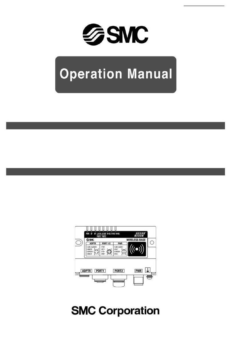
Base module
PROFINET communication
specifications
q
e
rt
y
u
w
No. LED name Function Color of LED Operation
1PWR
Power supply
voltage
(US1/US2)
Green LED
is ON.
Power supply voltage for control and input (US1) is normal,
and power supply voltage for output (US2) is normal.
Green LED
flashes.
Power supply voltage for control and input (US1) is normal,
and power supply voltage for output (US2) is abnormal.
(Applicable when the output power supply voltage monitoring setting is enabled)
Red LED
flashes.
Abnormal power supply voltage level for control and input (US1)
(Applicable when the control and input power supply voltage monitoring setting is enabled)
OFF Power supply for control and input (US1) is not supplied.
2SF Base module
system status
OFF Normal operation
Green LED flashes.
Node flashing test command has been received.
Red LED
flashes.
Restorable error is detected. (LED flashes when one
diagnostic information item or more is detected.)
·
Abnormal power supply voltage level for control and input (US1)
(Applicable when the control and input power supply
voltage monitoring setting is enabled)
·Abnormal power supply voltage level for output (US2)
(Applicable when the output power supply voltage
monitoring setting is enabled)
·Excessive I/O setting inputs/outputs
·Analog I/O upper set limit exceeded
·Analog input range upper and lower limit exceeded
·Abnormal number of remote connections
·Error in communication between units
·EX600 I/O unit detects diagnostic information
·Valve diagnostic information detected
Red LED is ON.
Non-restorable error is detected. (e.g. Hardware failure)
3BF
PROFINET
connection
status
OFF PROFINET communication is established.
Red LED
flashes.
The PROFINET controller setting and the EX600 configu-
ration data are mismatched.
Red LED
is ON.
PROFINET communication is not established.
· The power supply of the PROFINET controller is OFF.
·There is a defective connection in the communication
cable between the PROFINET controller and the base
module.
·The PROFINET controller or the base module has
broken down.
·The PROFINET controller setting and the device name
of the base module are mismatched.
4W-SS
Radio wave
receiving intensity
(For communication
from remote to base)
Green LED is ON.
Received power level of all remotes is 3.
Green LED flashes. (1 Hz)
There are connected remotes with received power level 2.
Green LED flashes. (2 Hz)
There are connected remotes with received power level 1.
Red LED flashes.
No remotes connected.
OFF Remote module is not registered.
5W-NS
Wireless
communication
connection
status
Green LED is ON.
All remote modules are connected correctly.
Green LED flashes.
There are unconnected remote modules.
Red LED flashes.
All remote modules are unconnected.
Red LED
is ON.
All remote modules are unconnected.
(Non-restorable error in wireless communication)
Red/Green
Wireless communication connection is under construction. (Pairing)
Orange LED is ON.
Forced output mode
OFF Remote module is not registered.
6W-MS
Remote module
connection
system status
Green LED is ON.
Remote module is normal.
Red LED
flashes.
Restorable error is detected. (LED flashes when one
diagnostic information item or more is detected.)
·
Abnormal power supply voltage level for control and input (US1)
·Abnormal power supply voltage level for output (US2)
·Excessive I/O setting inputs/outputs
·Analog I/O upper set limit exceeded
·Analog input range upper and lower limit exceeded
·Error in communication between units
·EX600 I/O unit detects diagnostic information
·Valve diagnostic information detected
Red LED is ON.
Non-restorable error is detected. (e.g. Hardware failure)
OFF No remote module connected.
7
LINK/ACT1
LINK/ACT2
Communication status of
PROFINET ports 1 and 2
Green LED is ON.
Link, No Activity
Green LED flashes.
Link, Activity
OFF No Link, No Activity
16
「
web-kigou
レイヤー」です。
※このレイヤーは、通常は隠しておく(
web
校了時のみ表示)
「
web-kigou
レイヤー」です。
※このレイヤーは、通常は隠しておく(
web
校了時のみ表示)
A

EX600-W Series
LED Display
Remote module No. LED name Function Color of LED Operation
1PWR (V)
Power supply
voltage for
output (US2)
Green LED is ON.
Power supply voltage for output (US2) is normal.
Red LED
flashes.
Power supply voltage for output (US2) is abnormal.
(Indication only. The product can be operated. Applicable when
the output power supply voltage monitoring setting is enabled)
OFF Power supply for control and input (US1) is not supplied.
2W-SS
Radio wave
receiving intensity
(For communication
from base to
remote)
Green LED is ON.
Received power level is 3.
Green LED flashes. (1 Hz)
Received power level is 2.
Green LED flashes. (2 Hz)
Received power level is 1.
Red LED flashes.
Wireless communication is not connected.
OFF Base module is not registered.
3W-NS
Wireless
communication
connection
status
Green LED is ON
Remote is connected correctly.
Red LED flashes.
No remotes connected.
Red LED is ON.
No remotes connected (Non-restorable error in wireless communication)
Red/Green
Wireless communication connection is under construction. (Pairing)
Orange LED is ON.
Forced output mode
OFF Base module is not registered.
4MS Remote module
system status
Green LED is ON.
Remote module is normal.
Red LED
flashes.
Restorable error is detected. (LED flashes when one
diagnostic information item or more is detected.)
·
Abnormal power supply voltage level for control and input
(Applicable when the control and input power supply
voltage monitoring setting is enabled)
·Excessive I/O setting inputs/outputs
·Analog I/O upper set limit exceeded
·Analog input range upper and lower limit exceeded
·Error in communication between units
·EX600 I/O unit detects diagnostic information
·Valve diagnostic information detected
Red LED is ON.
Non-restorable error is detected. (e.g. Hardware failure)
OFF Power supply for control and input (US1) is not supplied.
q
w
r
e
17
「
web-kigou
レイヤー」です。
※このレイヤーは、通常は隠しておく(
web
校了時のみ表示)
「
web-kigou
レイヤー」です。
※このレイヤーは、通常は隠しておく(
web
校了時のみ表示)
A
Table of contents
Other SMC Networks Microphone System manuals

SMC Networks
SMC Networks EX600-WSV User manual

SMC Networks
SMC Networks EX140-SMJ1 Series User manual

SMC Networks
SMC Networks EX600-WEN User manual

SMC Networks
SMC Networks EXW1 Series User manual

SMC Networks
SMC Networks EX600-ED Series User manual

SMC Networks
SMC Networks EXW1/EX600-W User manual

SMC Networks
SMC Networks EXW1-BPNAC1 User manual

SMC Networks
SMC Networks SI Unit User manual