ProMinent ProMaqua Dulcodes A User manual

Dulcodes A
UV system
Assembly and operating instructions
A1144
Please stick the nameplate here
EN
Original operating instructions (2006/42/EC)Part no. 985175 Version: BA DS 064 09/19 EN
Please carefully read these operating instructions before use. · Do not discard.
The operator shall be liable for any damage caused by installation or operating errors.
The latest version of the operating instructions are available on our homepage.

In order to make it easier to read, this document uses the male
form in grammatical structures but with an implied neutral sense. It
is aimed equally at both men and women. We kindly ask female
readers for their understanding in this simplification of the text.
Please read the supplementary information in its entirety.
Information
This provides important information relating to the
correct operation of the unit or is intended to make
your work easier.
Warning information
Warning information includes detailed descriptions of the haz‐
ardous situation, see
Ä Chapter 3.1 ‘Labelling of Warning Informa‐
tion’ on page 10
.
The following symbols are used to highlight instructions, links, lists,
results and other elements in this document:
Tab. 1: More symbols
Symbol Description
Action, step by step.
⇨Outcome of an action.
Links to elements or sections of these instructions or other applicable documents.
nList without set order.
[Button]
Display element (e.g. indicators).
Operating element (e.g. button, switch).
‘Display /GUI’
Screen elements (e.g. buttons, assignment of function keys).
CODE Presentation of software elements and/or texts.
General non-discriminatory approach
Supplementary information
Supplemental directives
2

Table of contents
1 About this system.................................................................. 5
1.1 Correct and Proper Use ............................................... 5
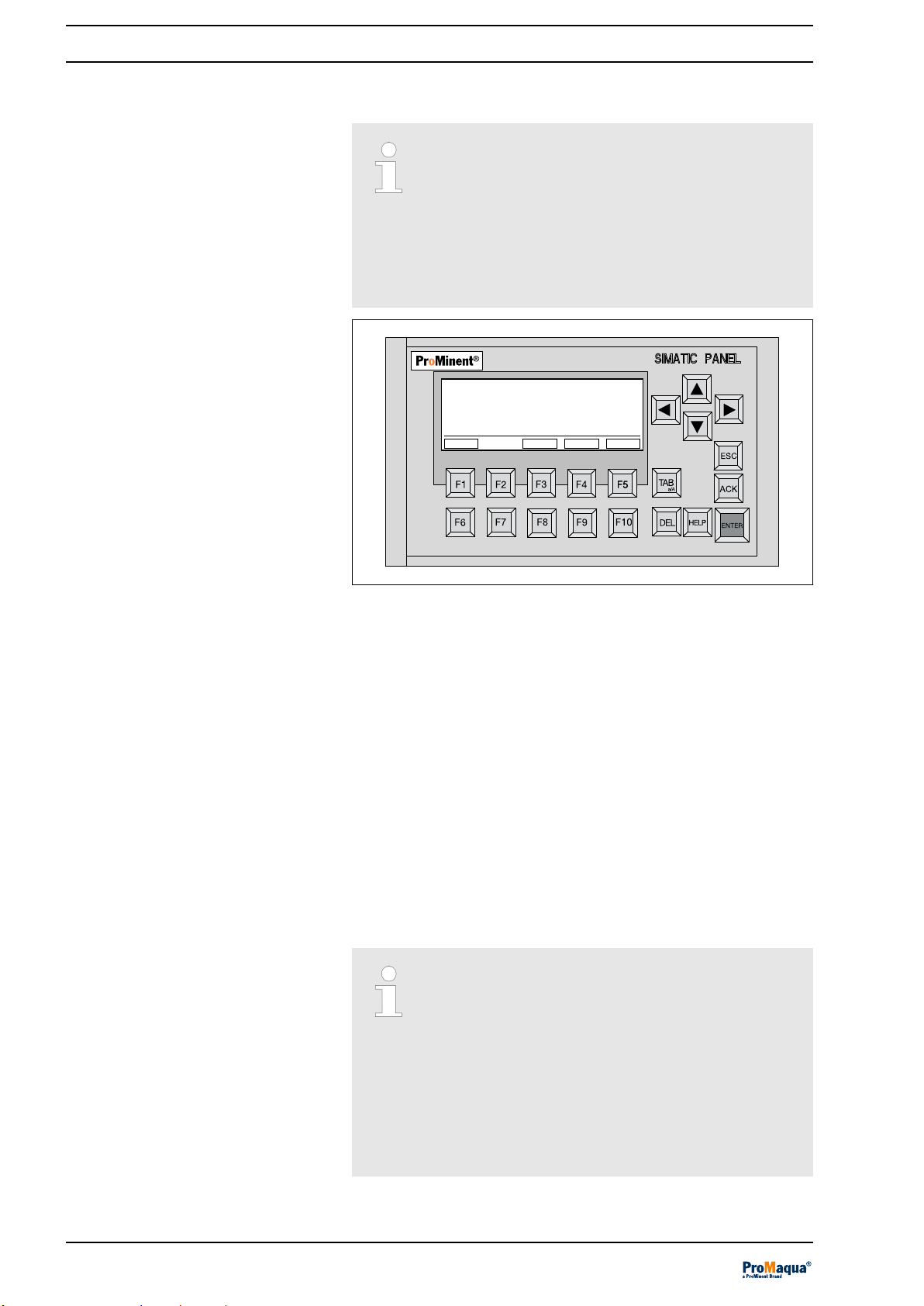
2 General information and operating concept.......................... 6
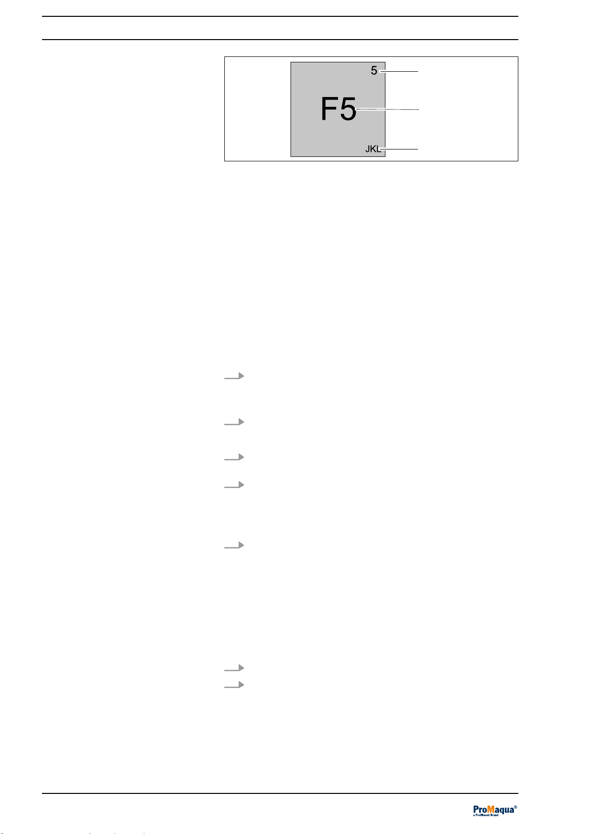
2.1 Entering data on the KP300 Basic................................ 7
3 Safety chapter..................................................................... 10
3.1 Labelling of Warning Information................................ 10
3.2 User qualification........................................................ 12
3.3 Dulcodes safety information....................................... 13
3.4 Safety equipment........................................................ 14
3.5 Information in the Event of an Emergency ................. 14
4 Permissible ambient conditions.......................................... 15
5 Function.............................................................................. 16
5.1 Commissioning........................................................... 16
5.2 Normal mode.............................................................. 17
5.3 Controlled operation................................................... 17
5.4 Automatic wiper.......................................................... 17
5.5 Temperature Monitoring ............................................ 17
5.6 Switching off............................................................... 18
5.7 Cool down................................................................... 18
5.8 Behaviour should the supply voltage fail.................... 18
6 Control................................................................................ 19
6.1 Version........................................................................ 19
6.2 Display of UV dose and radiation intensity (UV inten‐
sity)............................................................................. 20
6.3 Adjusting the Dulcodes A control................................ 20
6.4 Display........................................................................ 23
6.4.1 Functions of the keys in
[Unit Off]
status ................ 23
6.4.2 Functions of the keys in
[PAUSE]
status ................ 24
6.4.3 Functions of the keys in
[COOLING]
status ............ 26
6.4.4 Functions of the keys in
[Startup]
status ................. 27
6.4.5 The function of the keys in
[Commissioning rinse]
mode........................................................................ 28
6.4.6 Functions of keys in
[Free rinse]
mode.................... 29
6.4.7 The function of the keys in
[Normal operation]
mode........................................................................ 31
6.4.8 The function of the keys in
[Post-burning]
status..... 32
6.4.9 The function of the keys in
[Fault]
status ................ 33
6.4.10 Control of the automatic wiper............................... 34
6.5 Menu........................................................................... 35
6.5.1 The first operating and display level........................ 35
6.5.2 The second operating and display level.................. 38
6.5.3 The third operating and display level....................... 45
7 Assembly and installation................................................... 50
7.1 Installation details ...................................................... 51
7.2 Radiation chamber...................................................... 53
7.2.1 Assembly................................................................. 53
7.2.2 Attach the warning label.......................................... 54
7.2.3 Hydraulic Connections ............................................ 54
7.3 Control cabinet and control......................................... 55
Table of contents
3

7.3.1 Assembly ................................................................ 55
7.3.2 Electrical connections.............................................. 55
7.3.3 Fitting the temperature sensor................................. 55
7.4 Fitting the UV lamp protection tube............................ 56
7.4.1 Fitting the UV lamp protection tube with automatic
wiper........................................................................ 56
7.5 Assembly and connection of the UV lamp.................. 56
7.6 Assembly and installation of the wiper motor............. 58
8 Commissioning................................................................... 59
8.1 Check the control system programming..................... 59
8.2 Leak testing and ventilation of the reactor.................. 60
8.3 Switching on the UV system....................................... 60
9 Maintenance....................................................................... 61
9.1 Maintaining and caring for the KP 300........................ 62
9.2 Cleaning...................................................................... 63
9.2.1 Cleaning the UV lamp protection tube..................... 63
9.2.2 Cleaning after dismantling the UV lamp protection
tube.......................................................................... 64
9.2.3 Cleaning with Cleaning Solution by Filling the UV
System..................................................................... 67
9.2.4 Cleaning the UV Sensor ......................................... 68
9.3 Maintenance of the wearing parts............................... 69
9.3.1 Tools........................................................................ 69
9.3.2 Replacing wearing parts after an operating period
of one year............................................................... 70
9.3.3 Instructions: Replacing the wearing parts ............... 70
9.4 Replacing the lamp..................................................... 90
9.5 Calibration of the UV sensor....................................... 92
9.5.1
[Sensor calibration]
.................................................. 93
9.6 Replacing the Filter Mats............................................ 93
10 Troubleshooting.................................................................. 95
11 Technical data..................................................................... 99
11.1 Dimensions Sheet................................................... 101
11.2 Electrical data......................................................... 105
12 Appendix........................................................................... 107
12.1 Spare parts 1 kW - 3 kW......................................... 107
12.2 Spare parts 2x2 kW, 2x3 kW, 3x3 kW multiple lamp
system.................................................................... 111
12.3 UV system operating log......................................... 113
12.4 Disposal of used parts............................................ 114
12.5 Declaration of Conformity....................................... 115
13 Index................................................................................. 116
Table of contents
4

1 About this system
Dulcodes A UV systems are used for disinfection and to support
the disinfection of:
nPotable water
nProcess water
nSwimming pool water
In the treatment of swimming pool water, harmful substances, such
as chloramines, can be effectively reduced by UV radiation and
also germs, which are difficult to combat with chlorine, can be
safely killed. UV radiation is proven for the reduction of inorganic
combined chlorine. Organically bound chlorine is generally more
stable and cannot be reduced by UV radiation.
Dulcodes UV systems are supplied ready for connection. They are
available in different designs, defined by their identity code. The
performance data can be found in the data sheet enclosed with the
Dulcodes UV system.
Scope of supply:
nRadiation chamber
nLamp with lamp protection tube
nUV-C sensor
nTemperature switch
nAutomatic wiper
nControl cabinet with control
nDocumentation
1.1 Correct and Proper Use
Correct and Proper Use
The operator is liable for damage caused by instal‐
lation and operating errors!
–
The system is intended solely for the treatment
of water.
–
The system may only be used in accordance
with the technical data and specifications out‐
lined in the operating instructions!
–
Any other use or modification of the system is
prohibited.
–
The system may only be operated by trained
and authorised personnel!
–
It is imperative that the information in the oper‐
ating instructions relating to the different
phases of the unit's service life is observed!
Application
About this system
5

2 General information and operating concept
Display background lighting
To ensure easy monitoring of the UV system ope‐
ration, the background lighting of the display
changes according to the UV system operating
status.
–
Normal operation: green lighting
–
Warning: yellow lighting
–
Fault: red lighting
A1169
06/12/2012 10:06:53
START
FAULTS
MENU
UNIT OFF
WIPER
Unit ready for start
Fig. 1: Status [UNIT OFF]
In operation, as well as in the
[UNIT OFF]
status, you can change
to the
[menu]
by pressing
[F5]
. The
[menu]
contains additional
information about statuses, settings and system history.
Alongside this information, the menu area is also used to adjust the
control.
If no key is pressed for 5 minutes, then the UV system automati‐
cally exits the
[menu]
and the standard display for the current oper‐
ating status is displayed.
The
[menu]
is set to the corresponding operating statuses, that is
to say when the UV system is running, all events are monitored
and treated accordingly to the operating status, but are not dis‐
played. If, due to events, the control changes to one of the statuses
[POST-BURNING]
,
[PAUSE]
,
[RINSE]
or
[FAULT]
the system exits
the
[menu]
and the display corresponding to the operating status
appears.
The function keys F1 ... F10
Essentially the arrow keys and the [TAB] key can
be used as an alternative to the function keys
[F1] ... [F10]. These operating instructions describe
operation of the system using the function keys
[F1] ... [F10] as a matter of course. Use of the
arrow keys and the [TAB] key is only described
where this is unavoidable.
This approach should improve the legibility and
ease of understanding of the operating instruc‐
tions.
General information
The operating concept
General information and operating concept
6

You can call up the individual functions using the function keys
[F1]
...
[F5]
.
The KP300 Basic is equipped with system keys. The system keys
are subdivided as follows:
nControl keys
nFunction keys with integrated alphanumeric keys
Tab. 2: The following table outlines the function and effect of the operating device control keys
Key Function Effect
A1442
Move cursor Operating objects: Activates the next operating object in the
respective direction
Entry: Moves the cursor in the relevant direction
List: Selects the next list entry.
ENTER Confirm or activate Menu: Executes the selected command. Entry: Confirms and
ends entry. List: Activates the operation
ESC Cancels operation Value entry: Resets the original value.
Window: Closes the window without applying a change.
Help: Closes help and returns to the previous view.
ACK Acknowledge mes‐
sage
Depending on the project planning, closes the message currently
displayed or selected or all the messages in an acknowledged
group.
DEL Delete character Deletes the character at the cursor position. The following char‐
acters are shifted one position to the left.
HELP Display help text Displays the planned help text for the selected operating object.
If no help text is planned, no help is displayed.
TAB Switch between
upper case and
lower case
Switches between upper case and lower case when inputting
text. The following characters are then typed either all in upper
case or all in lower case.
TAB Select next oper‐
ating object
Selects the next operating object in the project within the planned
TAB sequence.
2.1 Entering data on the KP300 Basic
The function keys of the KP300 Basic have the same operating
concept as the keypad of a mobile phone. Each function key has
multiple assignments with the letters of the alphabet and special
characters as well as each being allocated a number. When input‐
ting a value, the available characters are displayed in a menu on
the display. Each time a function key is pressed, the selection in
the menu moves to the right. At the end the selection jumps back
to the start.
Numerical and alphanumerical assignment always has the fol‐
lowing sequence when values are being entered:
nLetters, e.g. JKL
nNumber e.g. 5
nSpecial characters and umlauts (optional)
Overview
Introduction
General information and operating concept
7

1
2
3
A1441
Fig. 2: The figure shows the assignment for the function key [F5].
1. Numerical assignment; automatically active when inputting
numerical values
2. Function assignment is disabled if you use
[ENTER]
in the con‐
trol panel of project to switch to editing mode. Instead, the
numerical and / or alphanumerical assignment is activated.
Simultaneously a message is emitted that the function keys are
disabled.
3. Alphabetical assignment; automatically active when alphanu‐
merical values are entered. Numerical assignment is also avail‐
able. When entering hexadecimal values, only the alphanumer‐
ical assignment of keys
[A]
to
[F]
plus numerical assignment are
active
On the KP300 Basic, you either move within the menu or operate
the current project.
Proceed as follows:
1. To move around in the menu of the KP300 Basic, use the
cursor keys or press
[TAB]
ðHighlighting is shifted to the corresponding menu entry.
2. To execute a menu command, press
[ENTER]
ðThe next menu level is displayed.
3. If a menu level contains an input field, use the function keys
to enter the corresponding value.
4. If a menu level contains a list:
nPress
[ENTER]
to activate operation of the list
nUse the cursor keys to switch between the list entries.
nPress
[ENTER]
to select a list entry
5. To enter a value in the menu:
nPress
[ENTER]
to accept a value
nPress
[ESC]
to discard a value or return to the overlying
menu
nPress
[Del]
to delete a value
Use the function keys to enter numbers and characters.
Proceed as follows:
1. Activate operation of the operating object.
2. Press the corresponding key until the desired character is
shown on the screen.
Depending on the format of the operating object, you can
limit the assignment of the function keys to letters or num‐
bers.
The desired characters are applied after approximately one
second or immediately after pressing another key.
Menu operation
Entering numbers and characters
General information and operating concept
8

3. Use the cursor keys to navigate within the entered character
chain.
4. Apply the entry with
[ENTER]
You can plan limit values for variables. If you enter a value that is
outside these limits, the value is not applied. If a message window
has been planned for the project, a system message is emitted and
the original value is displayed again.
Limit value checking with numerical
values
General information and operating concept
9

3 Safety chapter
3.1 Labelling of Warning Information
These operating instructions provide information on the technical
data and functions of the product. These operating instructions pro‐
vide detailed warning information and are provided as clear step-
by-step instructions.
The warning information and notes are categorised according to
the following scheme. A number of different symbols are used to
denote different situations. The symbols shown here serve only as
examples.
DANGER!
Nature and source of the danger
Consequence: Fatal or very serious injuries.
Measure to be taken to avoid this danger.
Description of hazard
– Denotes an immediate threatening danger. If
the situation is disregarded, it will result in fatal
or very serious injuries.
WARNING!
Nature and source of the danger
Possible consequence: Fatal or very serious inju‐
ries.
Measure to be taken to avoid this danger.
– Denotes a possibly hazardous situation. If the
situation is disregarded, it could result in fatal
or very serious injuries.
CAUTION!
Nature and source of the danger
Possible consequence: Slight or minor injuries.
Material damage.
Measure to be taken to avoid this danger.
– Denotes a possibly hazardous situation. If the
situation is disregarded, it could result in slight
or minor injuries. May also be used as a
warning about material damage.
NOTICE!
Nature and source of the danger
Damage to the product or its surroundings.
Measure to be taken to avoid this danger.
– Denotes a possibly damaging situation. If the
situation is disregarded, the product or an
object in its vicinity could be damaged.
Introduction
Safety chapter
10

Type of information
Hints on use and additional information.
Source of the information. Additional measures.
–
Denotes hints on use and other useful informa‐
tion. It does not indicate a hazardous or dam‐
aging situation.
Safety chapter
11

3.2 User qualification
WARNING!
Danger of injury with inadequately qualified per‐
sonnel
The operator of the system / equipment is respon‐
sible for ensuring that the qualifications are ful‐
filled.
If inadequately qualified personnel work on the unit
or loiter in the hazard zone of the unit, this could
result in dangers that could cause serious injuries
and material damage.
– All work on the unit should therefore only be
conducted by qualified personnel.
– Unqualified personnel should be kept away
from the hazard zone.
The pertinent accident prevention regulations, as
well as all other generally acknowledged safety
regulations, must be adhered to.
Training Definition
Instructed personnel An instructed person is deemed to be a person who has been instructed and,
if required, trained in the tasks assigned to him and possible dangers that
could result from improper behaviour, as well as having been instructed in the
required protective equipment and protective measures.
Trained user A trained user is a person who fulfils the requirements made of an instructed
person and who has also received additional training specific to the system
from the manufacturer or another authorised distribution partner.
Trained, qualified per‐
sonnel
A trained, qualified employee is deemed to be a person who is able to assess
the tasks assigned to him and recognize possible hazards based on his
training, knowledge and experience, as well as knowledge of pertinent regula‐
tions. A trained, qualified employee must be able to perform the tasks
assigned to him independently with the assistance of drawing documentation
and parts lists. The assessment of a person's technical training can also be
based on several years of work in the relevant field.
Electrical technician An electrical technician is able to complete work on electrical systems and rec‐
ognise and avoid possible dangers independently based on his technical
training and experience as well as knowledge of pertinent standards and regu‐
lations. An electrical technician must be able to perform the tasks assigned to
him independently with the assistance of drawing documentation, parts lists,
terminal and circuit diagrams. The electrical technician must be specifically
trained for the working environment in which the electrical technician is
employed and be conversant with the relevant standards and regulations.
Service The Service department refers to service technicians, who have received
proven training and have been authorised by the manufacturer to work on the
system.
Safety chapter
12

3.3 Dulcodes safety information
WARNING!
UV-C radiation
Possible consequence: Serious injuries
UV-C radiation is harmful to the eyes and skin
– Only operate the UV lamp
UV-C
when it is fully
fitted and installed
– Install the UV lamp into the UV system in
accordance with the regulations prior to com‐
missioning
WARNING!
Live parts!
Possible consequence: Fatal or very serious inju‐
ries
– Measure: Disconnect the device from the
power supply before opening it.
– Disconnect damaged and defective devices or
devices that have been tampered with from the
power supply
WARNING!
Insufficient water treatment
Possible consequence: Illness or disease
Please read the technical data sheet for your UV
system
Ensure that:
– the maximum permissible water flow rate is not
exceeded and
– the UV transmission does not fall below the
permissible level,
– as otherwise adequate treatment of the
water cannot be guaranteed.
CAUTION!
Overheating of lamp and treatment chamber
Possible consequence: Material damage
– Ensure that, with the exception of when the UV
lamp is warming up, the radiation chamber has
a flow rate of at least 5% of the nominal flow
rate, so that the radiation chamber cannot
overheat.
– Only switch on the UV system after the radia‐
tion chamber has been filled with water.
– Switch the UV system off if the flow of water is
interrupted.
Safety chapter
13

CAUTION!
Unauthorised operating parameters
Possible consequence: Material damage
Ensure that:
– The installation place is dry and frost-free
– There is guaranteed protection for the UV
system from chemicals, dyes and vapours
– The ambient temperature and the radiation
temperature in the direct vicinity of the system
do not exceed 40°C
– The maximum permissible operating pressure
is not exceeded and
– There are no solid particles and no turbidity in
the water to be treated
– If necessary, fit a suitable filter prior to the UV
system.
3.4 Safety equipment
ATTENTION: Hazardous ultraviolet radiation
UV-C
UV-C radiation is harmful to the eyes and skin! The UV lamps
may only be operated when installed. The UV system should be
installed in accordance with all pertinent regulations prior to com‐
missioning the UV lamps.
ATTENTION: Hazard
Disconnect the system from the mains power supply or switch
off the master switch prior to commencing maintenance work.
Depressurise the reactor prior to commencing maintenance work.
Disconnect the system from the mains power supply or switch
off the master switch prior to opening.
3.5 Information in the Event of an Emergency
In the event of an emergency, switch the red-yellow main switch on
the side of the control cabinet to OFF or disconnect from the mains
power supply.
Labels on reactor
Labels on control cabinet
Safety chapter
14

4 Permissible ambient conditions
Permissible ambient temperature: - 20 °C ... + 70 °C.
Humidity: maximum 95 % relative air humidity, non-condensing.
Other: No dust, no direct sunlight.
Permissible ambient temperature: + 5 °C ... + 40 °C.
Humidity: maximum 92 % relative air humidity, non-condensing.
Other ambient conditions: No dust, no direct sunlight. No corrosive
gases, vapours and dust.
During storage
During operation
Permissible ambient conditions
15

5 Function
The water to be treated flows through the stainless steel radiation
chamber past the UV lamp. UV radiation kills the germs and
destroys substances, like chloramines, in the swimming pool water.
The UV medium pressure lamp produces UV-C radiation. The UV
lamp is located in a quartz lamp protection tube with good UV
transparency.
The design of the radiation chamber and the flow of radiation
deliver even irradiation of the entire flow of water.
A control monitors the UV system in conjunction with the UV
sensor.
Shut-off valves and rinse valves do not form part of
the scope of delivery
The shut-off valves and rinse valves do not form
part of the scope of delivery of the UV system and
are provided by the operator on site.
A0917
1
2
3
4
5
7
6
2
2
Fig. 3: Typical installation layout for a UV system
1 Shut-off valve
2 Shut-off valve
3 Rinse valve
4 Sampling taps, fireproof
5 Reactor
6 UV sensor
7 Control
5.1 Commissioning
Once the UV system has been switched on, the UV lamp is ignited.
Following ignition, the UV lamp requires approximately 1 ... 3
minutes until it has reached its operating temperature.
If the safety threshold is not exceeded within the maximum permis‐
sible warm-up time, the controller switches the UV-system off and
goes into fault mode.
The UV-C sensor monitors the UV lamp: As soon as the UV output
has exceeded the warning threshold, the rinse valve opens for the
start rinse.
After the start rinse, the shut-off valve opens and the UV system
starts normal operation.
Installation diagram of a UV system
Function
16

5.2 Normal mode
In normal mode, the UV sensor continues to monitor the UV
output:
If the UV output falls below the warning threshold: a warning is
emitted.
If the UV output falls below the safety threshold: The shut-off valve,
fitted on site, closes, a wiper cycle is triggered and the flushing
valve, fitted on site, opens.
The UV system switches off and enters fault mode
if the safety threshold is still not exceeded after
completion of one wiping cycle.
In this mode, the operator of the UV system has to
ensure, for the purpose of disinfecting the water,
that the flow of water is reliably interrupted and no
unradiated water can be conveyed.
5.3 Controlled operation
UV radiation is automatically adjusted in controlled operation. The
UV sensor measures the UV output and forwards the measured
UV current value to the control. The UV setpoint is either entered
directly in the control (operating mode: control, internal
[INT]
) or
using a variable 4 ... 20 mA standard signal (operating mode: con‐
trol, external
[EXT]
).
5.4 Automatic wiper
During the wiper process, the warning and safety
thresholds are not monitored, consequently the
shadowing caused by the wiper does not trigger a
false alarm.
If you press the
[F3]
key
[Wiper]
in the standard display, then the
wiping process is triggered. This is independent of whether the
system is
‘ON’
or
‘OFF’
.
If you have activated regular wiping, then a wiping cycle occurs
automatically after the set interval has elapsed.
If the interval is set to
[0]
, then regular wiping is deactivated.
5.5 Temperature Monitoring
The water temperature in the radiation chamber is monitored
throughout the entire time the UV lamp is operating.
As soon as the water temperature exceeds the maximum tempera‐
ture, the UV system goes into fault mode.
Manually triggering a wiper cycle
Regular wiping
Function
17

5.6 Switching off
When the Off button on the UV control is pressed, the UV lamp
switches off once the set post-burning time has elapsed. The fac‐
tory setting is 30 seconds.
If you wish the UV lamp to switch off as soon as you have pressed
the off button, then you need to set the post-burning time to 0 sec‐
onds.
5.7 Cool down
As the UV lamp can only be re-ignited after switching off of the UV
system and sufficient cooling, the system goes into cooling down
mode.
During cooling mode, the UV system cannot be started. After the
pause status has been cleared during cool-down or
[START]
has
bee pressed during cooling down, the UV system only restarts after
the cooling-down period has ended.
5.8 Behaviour should the supply voltage fail
If the power fails, once the power supply has been reconnected the
UV system returns to the operating status in which it was before
the power failure.
40 seconds are needed to ramp up the HMI. The PLC (Program‐
mable Logic Controller) is ready for operation considerably faster.
To avoid ambiguous operating indicators and operating statuses,
operation is only enabled after 45 seconds.
When operation starts, all pending faults are reset if these faults
are no longer present. If the wiper is not in the home position, it is
moved back. If the power fails while the UV system is in operation,
then the system is always cooled down before being started
regardless of how long the power failure lasted. The cooling-down
phase is not shown on the display, but runs in the background. If
the power failure occurs while the UV system is cooling down, the
cooling down process is continued after the power has been
switched on again.
Should an automatic start not be desirable due to external compo‐
nents, the UV system must be switched from external to pause.
External faults result in a UV system fault, which then has to be
acknowledged. Separate acknowledgement can thereby be
avoided.
Function
18

6 Control
6.1 Version
As the electronics and software are continually subject to improve‐
ments, the version number was introduced as a means of identifi‐
cation. This number should be stated in the event of any com‐
plaints. The version number can be called up on the display.
nThe UV medium pressure control, based on a S7-1200, is used
to monitor and control a medium-pressure UV system one to
three medium-pressure lamps.
nThe operating and display unit is an HMI KP 300.
nThe UV lamps are actuated and monitored via an electronic
ballast.
nThe UV power is monitored.
nThe temperature of the radiation chamber and control cabinet
is monitored.
nThe wiper is controlled and monitored.
nSeveral valves can be controlled.
nSeveral additional inputs and outputs are used to operate the
UV system.
nThe lamp power can be controlled.
nOperating actions and events are recorded and saved together
with the date and time.
– The data can be displayed in tabular form on the display.
nThe radiation intensity or the lamp power is recorded and
saved at regular intervals together with the date and time.
– The radiation intensity can be presented as a simple dia‐
gram on the display.
Varying doses of UV may be necessary depending on the applica‐
tion. Often 600 J/m² is used to reduce combined chlorine and
400 J/m² for disinfection. The UV dose is calculated from the trans‐
mission of water and the water flow; refer to the data sheet for your
UV system. When calculating the UV dose, in accordance with the
data sheet, take into account ageing of the lamp and contamination
of the UV system, as well as possible transmission fluctuations in
the water quality.
If the transmission of water is not known, it must be calculated
when commissioning the UV system and checked with the max‐
imum permissible flow at the desired UV dose. The maximum flow,
as stated on the data sheet, must not be exceeded.
The UV system has over two freely adjustable output levels. The
control has a digital contact input to switch between these two
output levels. You can connect a suitable swimming pool controller
to measure the combined chlorine to this digital contact input in
swimming pool water treatment. In normal operation, the UV
system disinfects with with 400 J/m2. Should the swimming pool
controller measure too high a chloramine value, the UV system is
operated at 600 J/m 2, via the digital contact input, until the chlora‐
mine value calls again below the limit value set on the swimming
pool controller. This two-stage controller is not used when disin‐
fecting potable water.
General:
Information for designing a UV system
Two output levels
Control
19

6.2 Display of UV dose and radiation intensity (UV intensity)
The UV sensor monitors the radiation intensity of the UV system.
The radiation intensity (UV sensor signal) is given in W/m2 and is
displayed on the main screen of the HMI.
The UV dose is calculated depending on the:
nUV transmission,
nflow,
nradiation intensity.
The control calculates the UV dose displayed from this value.
A1514
06.12.2018 10:06:53
STOP
Fault
Menu
498 W/m2
Control INT
Time: 0000:01
Lamp power 1x979 W Lamp ON
WiperTREND
UV intensity
500 W/m2
UV intensity
Rinsing valve open
600 J/m2
UV dose
Fig. 4: Display of UV dose and radiation intensity (UV intensity)
In UV systems with connected flow measurement via the 0/4 ... 20
mA input, the current flow appears in the display in turn with the
dose display.
A2655
06.12.2019 10:06:53
STOP
Fault
Menu
498 W/m2
Control INT
Time: 0000:01
Lamp power 1x979 W Lamp ON
WiperTREND
UV intensity
500 W/m2
UV intensity
Rinse valve open
100 m3/h
Flow
Fig. 5: Display of the current flow [Flow](m3/h) in turn with the dose
display.
6.3 Adjusting the Dulcodes A control
External 4 ... 20 mA signal
In general, the external 4 ... 20 mA signal is pro‐
duced by a flow meter, to record the flow volume of
the system as a control variable for UV control.
Control
20
Table of contents
Other ProMinent Water System manuals
Popular Water System manuals by other brands

Fusion
Fusion Oxi-Gen 150-OXi-2P Installation, operation and maintenance manual

Halsey Taylor
Halsey Taylor HTVZD*1C series owner's manual

US Water Systems
US Water Systems L1-200 manual

Continental Refrigerator
Continental Refrigerator AWS-10 instruction manual

Water Protec
Water Protec LED 13 owner's manual

ATE
ATE HAAKE A82 manual

Reverse Osmosis
Reverse Osmosis Economy RO75 owner's manual

Crysalli
Crysalli CP2000-R-UC-BH installation guide

Watts
Watts BA 009MC Installation and operation manual

Spectra Watermakers
Spectra Watermakers Newport MkII Deluxe installation instructions

Kenmore
Kenmore 625.347031 manual

CTM
CTM CW-24H Installation & user manual