proMtec u-ICC 2.45 compact User manual
Erro! Use a guia Início para aplicar Überschrift 1 ao texto que deverá aparecer aqui.
0
MICROWAVE CONCENTRATION
MEASUREMENT
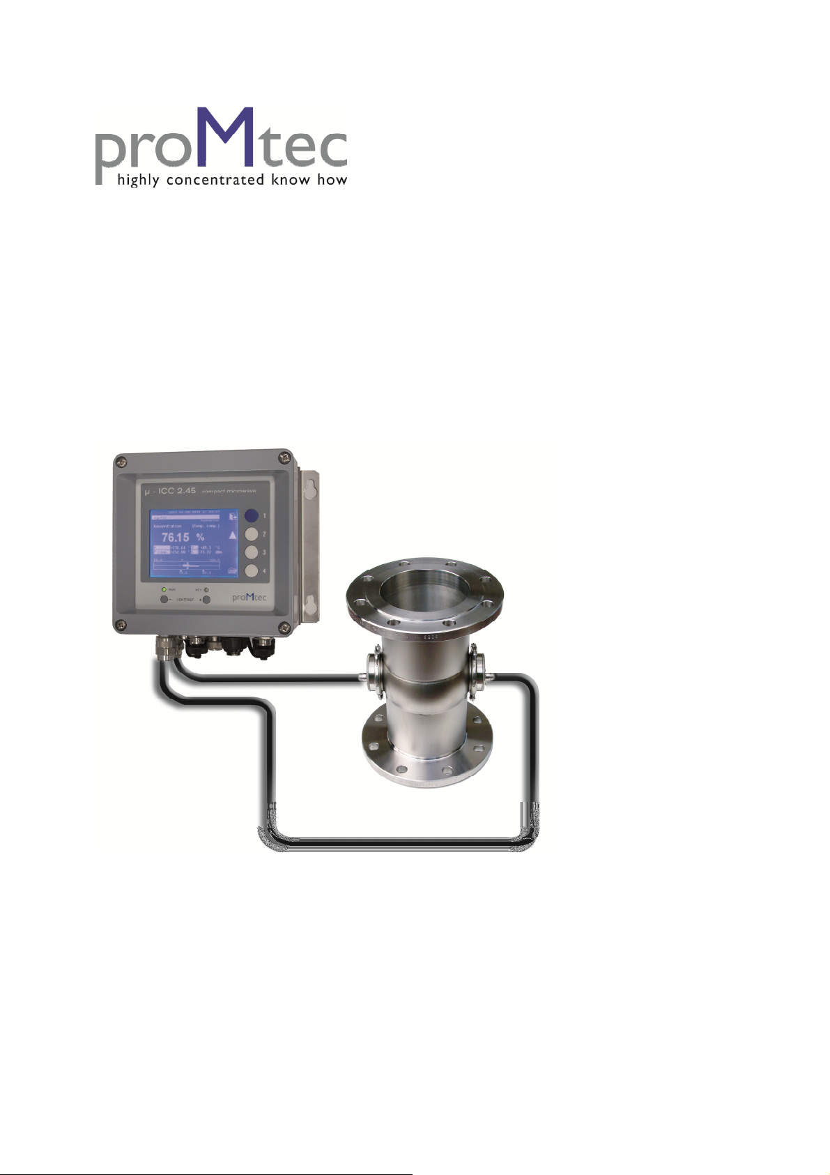
µ-ICC 2.45 compact
- MANUAL -
S/N: A01-PG10-MAE
Software version from V.0.21
Version No.: V3 2010-10-01

Erro! Use a guia Início para aplicar Überschrift 1 ao texto que deverá aparecer aqui.
1
1Safety instructions .................................................................................................................... 3
1.1 Symbols and indices ........................................................................................................... 3
1.2 Conventional usage............................................................................................................. 3
1.3 General safety & warning notices ...................................................................................... 3
1.3.1 Environmental conditions........................................................................................... 4
1.3.2 Electrical treatments ................................................................................................... 4
2System description µ-ICC 2.45 compact ................................................................................ 5
2.1 Measuring principle............................................................................................................ 5
2.2 Components ........................................................................................................................ 7
2.2.1 Evaluation unit............................................................................................................ 7
2.2.2 Sensor with probes...................................................................................................... 8
2.2.3 Cables ......................................................................................................................... 8
2.3 Installation .......................................................................................................................... 9
2.3.1 Installation of the Evaluation unit .............................................................................. 9
2.3.2 Connections and dimensions of the evaluation unit ................................................... 9
2.4 Installation recommendations........................................................................................... 13
3Menu topology and operation handling................................................................................ 15
3.1 Standard operation of the compact device........................................................................ 15
3.2 Operation via PC Remote ................................................................................................. 16
4First Start Up .......................................................................................................................... 19
4.1 Language .......................................................................................................................... 19
4.2 Date and Time .................................................................................................................. 19
4.3 System Reset..................................................................................................................... 19
4.4 Locking Keyboard ............................................................................................................ 20
4.4.1 Changing PIN number .............................................................................................. 20
4.4.2 Keyboard locking ..................................................................................................... 20
4.4.3 Keyboard unlocking ................................................................................................. 20
5Initial Sensor Configuration .................................................................................................. 21
5.1 Measurement mode........................................................................................................... 21
5.2 Amplification.................................................................................................................... 21
5.3 Measurement .................................................................................................................... 22
5.3.1 Temperature compensation....................................................................................... 22
5.3.2 Start coefficients ....................................................................................................... 22
5.3.3 Reference Point......................................................................................................... 23
5.4 Other Settings ................................................................................................................... 24
5.4.1 Sensor Description.................................................................................................... 24
5.4.2 Current Interface....................................................................................................... 24
6Data logging............................................................................................................................. 25
6.1 SD Card ............................................................................................................................ 25
6.2 USB HID .......................................................................................................................... 26
7Calibrating .............................................................................................................................. 27
7.1 Sampling........................................................................................................................... 27
7.2 First calibrating................................................................................................................. 27
7.3 Phase correction with level............................................................................................... 28
8Sensor Settings: save and reload ........................................................................................... 29
8.1 Sensor: Save settings, Load settings, Factory settings ..................................................... 29
8.1.1 How to save configuration........................................................................................ 29
8.1.2 How to load previously saved configuration............................................................ 29
8.1.3 How to reload factory settings.................................................................................. 29
8.2 Memory allocation: Load and Delete Internal and External Memory.............................. 29
8.2.1 Copying of configuration.......................................................................................... 29

Erro! Use a guia Início para aplicar Überschrift 1 ao texto que deverá aparecer aqui.
2
8.2.2 Deleting of configuration.......................................................................................... 30
8.2.3 Deleting of all memory............................................................................................. 30
9Moving of the measuring range............................................................................................. 31
10 Troubleshooting ...................................................................................................................... 32
10.1 PIN is not working............................................................................................................ 32
10.2 Constant offset.................................................................................................................. 32
11 Technical specifications.......................................................................................................... 33
12 Spare parts .............................................................................................................................. 34
13 Declaration of Conformity..................................................................................................... 35
14 Dimensional drawings ............................................................................................................ 36
14.1 Flat sensors with Inline-Gage DN 40 to 150 .................................................................... 36
14.2 Insertion sensor DN65 ...................................................................................................... 37
14.3 Rinsed insertion sensor DN65 .......................................................................................... 38
14.4 Insertion sensor DN80 ...................................................................................................... 39

Erro! Use a guia Início para aplicar Überschrift 1 ao texto que deverá aparecer aqui.
3
1 Safety instructions
1.1 Symbols and indices
In this manual there are consecutive symbols used to indicate safety
instructions.
Warning
possibility of danger for life and health
Attention
possibility of danger with light personal damages
Notice
possibility of material damage
Information
appliance tips and information
1.2 Conventional usage
The µ-ICC 2.45 compact is a measuring system based on a microwave
transmission technology. Therefore the product is transmitted by a very low
capacity of microwave radiation. The microwaves are completely harmless for
human and the environment. So there is no change of product properties.
This measuring system is produced according the latest safety requirements
for microwave devices. If there are legal regulations regarding the use of
microwaves the user has the responsibility to observe it.
It is not allowed to change the frequency of the device. Furthermore other
manipulation within the device could involve criminally consequences.
1.3 General safety & warning notices
The µ-ICC 2.45 compact is build with all included components according to
the latest state of technology and approved safety standards.
The housing is IP 65 certified and dedicated for outdoor use. Factory-
provided it is proofed and will be delivered reliably.
The safety and warning notices have to be strictly adhered to guarantee a
safe operating. The operating is only allowed if the system is in good order
and condition. There are only those persons allowed to operate with this
system, who are briefed and qualified. Reconstructions or changes, which
may have an influence on a safety operating are prohibited specifically.

Erro! Use a guia Início para aplicar Überschrift 1 ao texto que deverá aparecer aqui.
4
1.3.1 Environmental conditions
All components require non-corrosive environmental conditions while
transporting, stocking and operating.
1.3.2 Electrical treatments
The power supply must be interrupted during the installation and also for
technical service to avoid getting in contact with energized parts.
Before opening the evaluation unit the power supply must be interrupted! It’s
prohibited to work with opened device while it’s energized!
Spare part fuses must have the manufacturer specified values. To shorten
the circuit or any other manipulation are prohibited!
The evaluation unit must be earthed when it is mains-connected.
If there has gotten fluids into the device, it has to be interrupted the power
supply. Successive the device has to be controlled and cleaned by an
authorized person.
Without exact knowledge of this manual there must not be changes on the
installation or on any parameter settings. In addition there has to be known
the possible behaviour of the actuator and the influence on the
process.
Erro! Use a guia Início para aplicar Überschrift 1 ao texto que deverá aparecer aqui.
5
2 System description µ-ICC 2.45 compact
The µ-ICC 2.45 compact is a measuring device which combines a compact
housing with the latest technical standards in microwave measurement. It is
based on the successful and long time proofed µ-ICC 2.45.
In addition to the compact housing, this device comes with a lot of new
features like higher class components, simplified handling (like USB plug-in
for connection with a PC or an additional sample push-button) and also an
improved memory mode. The device is placed nearby the measuring location,
where it’s directly connected to the microwave sensor probes.
This manual will give you an explanation of the very simple handling and
implementation of this system.
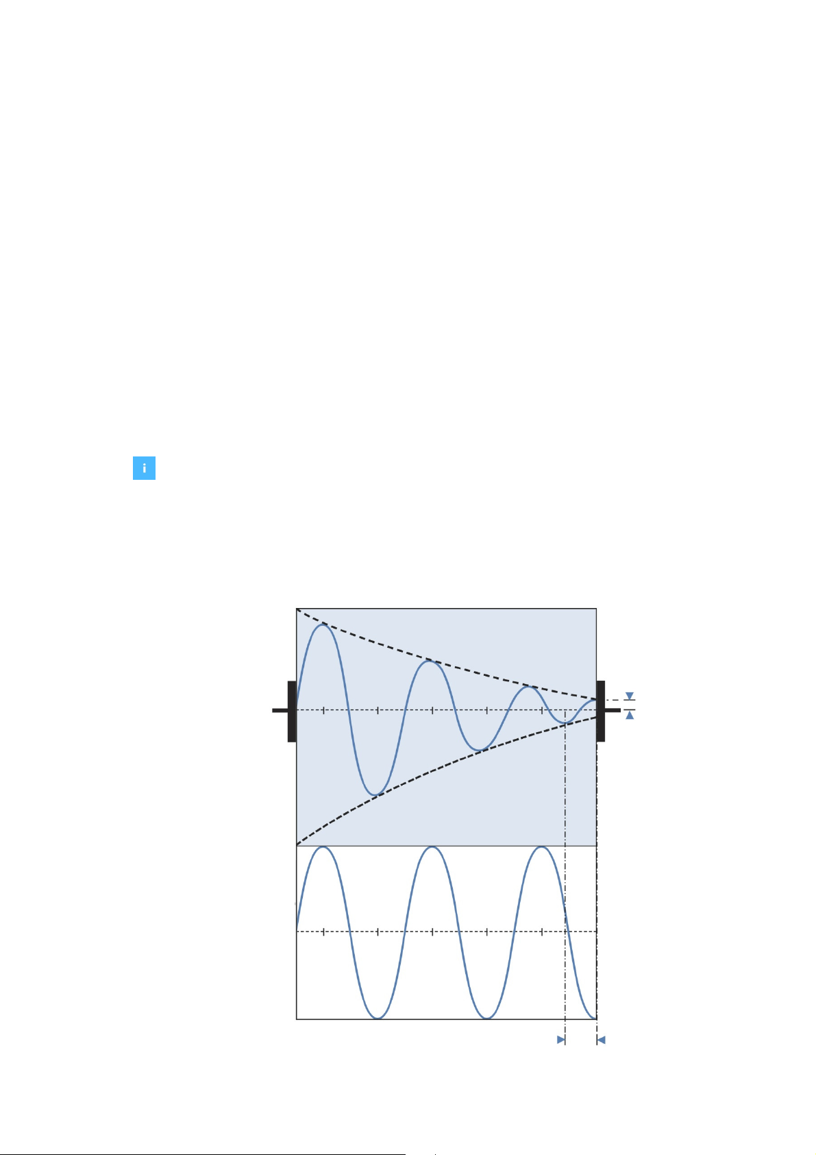
2.1 Measuring principle
Precondition for a successful measurement is the dielectricity of the medium.
Thus water contained products are in general good to measure, because the
microwaves are absorbed by free water molecules.
Another dependency is the distance between the sensor probes. Here it is
important that the signal strength is quite enough to get from the transmitter
to the receiver. Therefore proMtec offers the best fitting geometry for each
special application.
Reference signal
Phase shift
Attenuation
Transmitter
Receiver

Erro! Use a guia Início para aplicar Überschrift 1 ao texto que deverá aparecer aqui.
6
•The microwave signal is conducted into the medium by the transmitter. The
receiver collects the alleviated microwaves.
•The reference signal has the typical propagation without any influences. It is
used as a comparison with the alleviated microwave signal, to calculate a
phase shift (decrease of propagation velocity) or an attenuation.
•The phase shift is a decrease of the propagation velocity
•With this information it is calculated a value for the water content, density or
total dry matter content.

Erro! Use a guia Início para aplicar Überschrift 1 ao texto que deverá aparecer aqui.
7
2.2 Components
The measuring system is composed of two components – the evaluation unit
and the sensor probes. These probes are mounted into a pipe section (with
flat sensor probes) or into a vessel (insertion sensor probes) and are
connected via microwave cables with the evaluation unit.
The system is – like the standard version – temperature compensated.
Therefore it has to be connected to a temperature sensor, which is also
included within the system.
2.2.1 Evaluation unit
The evaluation unit is available in different types. As standard there is the
complete version with all features, alternatively it is also a version available
which is delivered without the display. Therefore it must be operated with a
PC via USB connection.

Erro! Use a guia Início para aplicar Überschrift 1 ao texto que deverá aparecer aqui.
8
2.2.2 Sensor with probes
proMtec offers a great variety of sensor types. Depending on the several
application proMtec designs the best fitting sensor type for implementing in
your process without complexity.
Standard versions are on the one hand inline pipe sections, where flat sensor
probes are fitted onto the pipe. On the other hand there are insertion sensors
with two probes used in a special flange for installation in vessels.
In each case the evaluation unit is directly connected with the sensor probes
via microwave cables.
2.2.3 Cables
The microwave cables attend to carry the signal directly to the measuring
point and backwards to the evaluation unit. These cables are produced in
accordance to the newest technology and with the best available shielding
and assure a low-loss propagation.
The cables are delivered with a length of one to three meters (depending on
the requirements). Despite the high shielding the cables should be as short
as possible to avoid too much power loss.
The temperature sensor itself is already mounted into the pipeline
respectively the insertion sensor tube. So you’ve just to connect the cable
with the sensor and on the other side with the connectors inside the device
(read chapter 2.3.2).

Erro! Use a guia Início para aplicar Überschrift 1 ao texto que deverá aparecer aqui.
9
2.3 Installation
2.3.1 Installation of the Evaluation unit
The device is delivered with a sub plate with four holding flaps (H x B = 120 x
180 mm for Ø 6 mm).
In cause of the limitation of microwave cables you should find a place nearby
the measuring location, where you can also operate comfortably. If there is no
adequate place for a comfortable operation, there is also the option to
operate with your PC via integrated USB port.
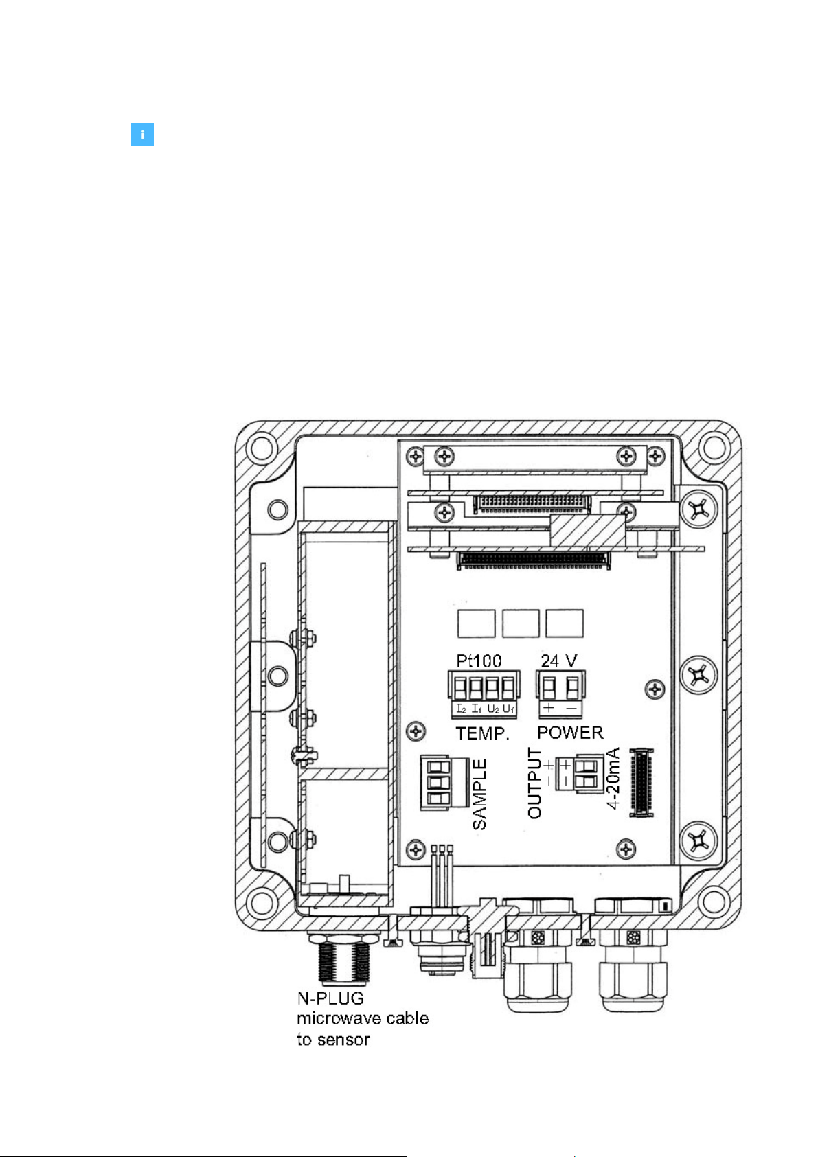
2.3.2 Connections and dimensions of the evaluation unit
To get an overview about the circuit points and the way how to connect
them, there is following connection list.
Before opening the evaluation unit and for connecting of any cable the power
supply must be interrupted!
Choose a dedicated mounting location that the cables are strain-relieved!
Do not snap the microwave cables!
With connecting of the signal output mind the polarity! This signal output is an
active current output.
Do not torque down the coupling nuts onto the evaluation unit too much!
Erro! Use a guia Início para aplicar Überschrift 1 ao texto que deverá aparecer aqui.
10
Connections:
•Microwave cables: There are two identical microwave cables; one for the
transmitter and one for the receiver. Both are connected with N-Plugs and it
doesn’t mind, which one is used for the “T”-Plug respectively the “R”-Plug.
•Pt 100 (4 wire): M12 plug
Pt 100 (2 wire): Cable entry (M16)
•Power supply: 24Voltage direct current (cable entry M16)
•Signal output: 4 – 20mA (4 wire M12 or cable entry M16)
•Sample push-button: M12 plug
•Data transfer: USB port for connection via PC
•Options: Cable entry (M16)
Connections inside the device:
Connections inside the sample push-button:

Erro! Use a guia Início para aplicar Überschrift 1 ao texto que deverá aparecer aqui.
11
If you’re using an insertion sensor, by default there is a Pt 100 with two wire
connection. In this case the plug-in is already bridged.
If you want to connect your own two wired Pt 100 you have to bridge I2 with
U2 and also I1 with U1, as you can see on the picture below.
bridged Pt 100 connector connected 2 wire Pt 100
For further modifications there are four additional connectors in the scope of
delivery, all in different dimensions as you can see on the picture below.

Erro! Use a guia Início para aplicar Überschrift 1 ao texto que deverá aparecer aqui.
12
Erro! Use a guia Início para aplicar Überschrift 1 ao texto que deverá aparecer aqui.
13
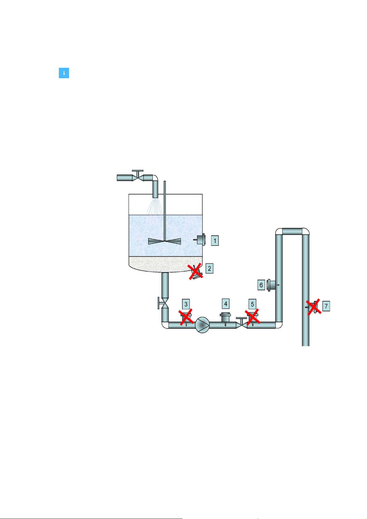
2.4 Installation recommendations
In order to get a reliable measurement it is necessary to have a good flow
through the sensors. This ensures that there is no caking on the sensor
probes.
If the product should contain any air or steam bubbles, there could be an
influence on the measurement. In cause of air within the product there could
be a not representative reflection of the microwaves and therefore an inexact
concentration value.
To avoid it, it is recommended to install the sensors in an up-going pipe after
a pump (pressure side). This installation ensures an air bubble-free product.
In addition, the product is more homogenized compared to a tank installation.
Possible recommended positions of sensor installation

Erro! Use a guia Início para aplicar Überschrift 1 ao texto que deverá aparecer aqui.
14
The best installation point is in the vertical pipe and enough away from the
pump. The recommended distance away from the pump is 4 times of the
diameter of the pipeline. The pipe must be completely filled by the product.
Position of Insertion sensor in the pipeline
Within the installation of insertion sensors into a tank wall you have to ensure
to position it below the minimum of the product level.
Erro! Use a guia Início para aplicar Überschrift 1 ao texto que deverá aparecer aqui.
15
3 Menu topology and operation handling
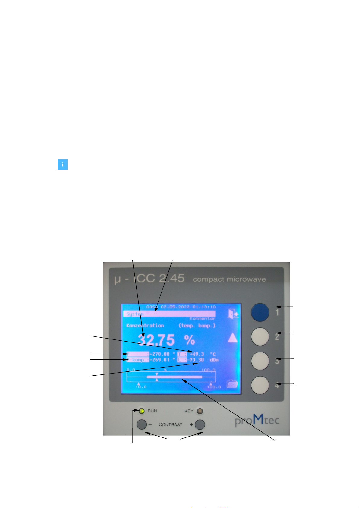
3.1 Standard operation of the compact device
The evaluation unit handles the data from the integrated microwave module.
It displays different values on the screen such as the measurement, the
Phase shift (raw and compensated), the temperature and the level. In
addition the values are supplied by a bar graph with trace (drag pointer)
which visualize the evolution of the measurement.
The evaluation unit is managed by the user-friendly menu. The menu can be
operated by the buttons F1, F2, F3 and F4 which are situated on the right
side of the housing. These buttons have different functions depending on the
current menu.
By default and while operating the display is in following mode:
With one-time selecting F2 the display shows additionally the values for
attenuation and signal voltage and also three traces for signal output, level
and phase. By selecting F2 it shows the main display again.
phase shift (in °)
F1
previous menu
clear trace
temperature (°C)
F2
increase value
F3
decrease value
display of connection indicator with trace
contrast regulation
RUN
green: ok
red: error
Level (in dBm)
Display of measurement
Serial number
Compensated
phase shift (in °)
KEY
F4
Main menu

Erro! Use a guia Início para aplicar Überschrift 1 ao texto que deverá aparecer aqui.
16
By selecting F4 the main menu is selected. By selecting F4 again you’ll get
into the next submenu. By selecting F1 you’ll get back to the previous menu.
The starting „System” main menu is structured in following submenus:
•Sensor: for setting parameters during configuration and
calibrating the measurement
•Basis configuration: basis settings (language, date & time), memory
storage options, etc.
•Memory allocation: storage of sensor settings and parameters
•Errorstate: overview with error number in case of any
problems
•Service: only for maintenance by proMtec
The several submenus are also explained more precisely in the following
chapters.
3.2 Operation via PC Remote
There is the option to operate the device via PC remote control. This is
integrated within the “µ-ICC 2.45 Datalog and Update” software.
display of signal output indicator with trace
Level indicator
Phase indicator
Voltage (in V)
Attenuation (in dB)

Erro! Use a guia Início para aplicar Überschrift 1 ao texto que deverá aparecer aqui.
17
If you ordered the compact device with blind cover, the software is already
included. Otherwise the software is available on request. Therefore please
get in contact with proMtec.
Before the first start up make sure that there is .NET Framework version 3.5
or higher already installed on your system. Otherwise you have to install
“dotnetfx35”, which is also available on the CD.
After that you could connect your PC with the Evaluation unit and start the
software.
SYSTEM / BASIS CONFIGURATION / USB DEVICE
Select „ System” , „ Basis configuration” and „ USB device”. Now select „
USB HID” and confirm by "OK" button.
Now you can start operating via pc remote control.
Therefore start “µ-ICC 2.45 Datalog and Update”, click to “Program” and
then choose “remote control”.
Now there is opening another window like below:
Here it is pictured the main display, where you can see the main value,
phase, temperature, compensated phase and the level. It is almost equal to
the device display.
To see the rest of the values click on the button “raw value”.
For operating you have to click on the button “settings”.
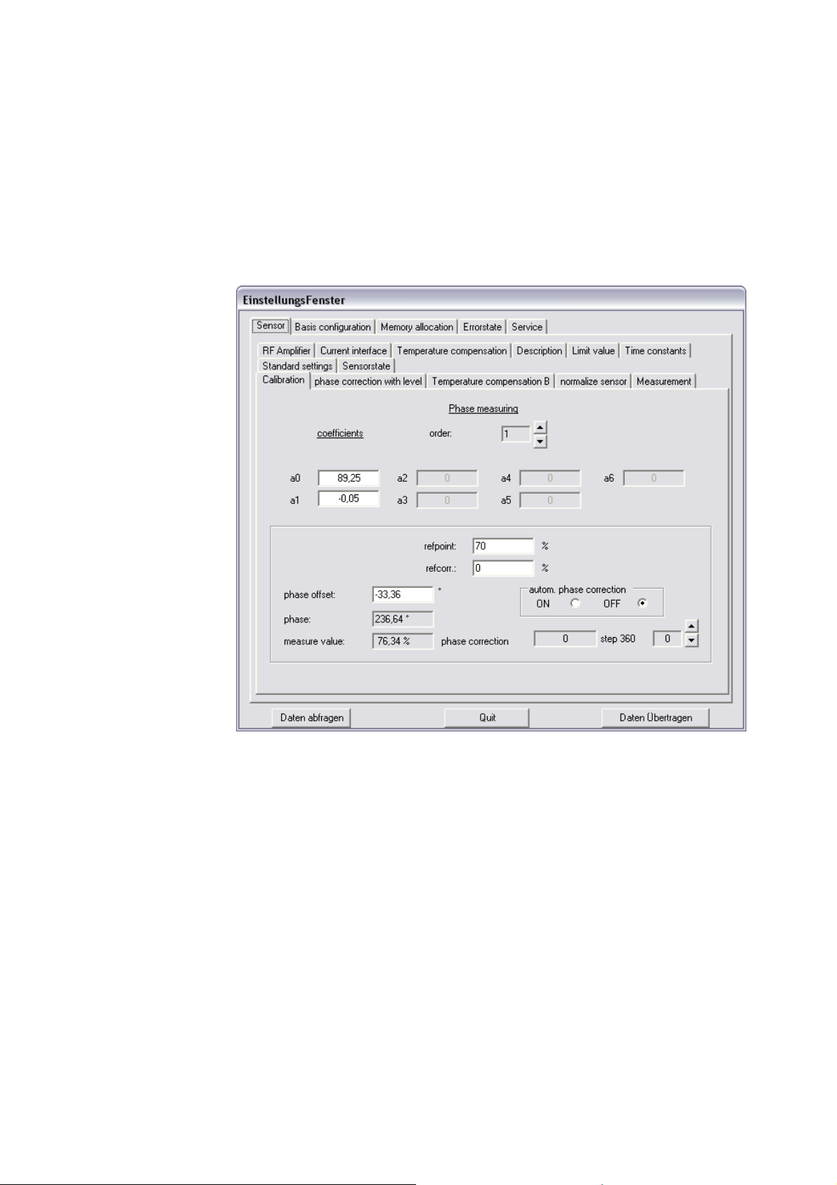
Erro! Use a guia Início para aplicar Überschrift 1 ao texto que deverá aparecer aqui.
18
Now you get another different looking window, where the menus and
submenus are shown in several tabs with the same structure like the device
menu structure.
To refresh the actual settings click on the button “data poll”, to take over the
settings to the device click on the button “data assume”.
To get back to main menu click on the button “Quit”.

Erro! Use a guia Início para aplicar Überschrift 1 ao texto que deverá aparecer aqui.
19
4 First Start Up
Before connecting the evaluation unit with power supply, make sure that the
microwave sensors are already connected to the evaluation unit.
With the first start up you should adjust basic settings; e.g. date and time.
4.1 Language
SYSTEM / BASIS CONFIGURATION / LANGUAGE
First of all you can choose the language from Deutsch, English, Francais, Italiano,
Español or Portugues-Standard.
Starting from „ System” main menu (by pressing F4), select „ Basis
configuration”, then select “Language”. Now you can select your preferred
language by "▲" and "▼" and confirm by the "OK" button.
4.2 Date and Time
SYSTEM / BASIS CONFIGURATION / DATE TIME
Here you can set date and time.
Starting from „ System” main menu, select „ Basis configuration”, then „Date
/Time”and „Time” can be entered by "▲" and "►" buttons and confirmed by
"OK" button. The „ Date” can be selected and entered in the same way.
4.3 System Reset
SYSTEM / BASIS CONFIGURATION / RESET
In case of configuration modifications it might be necessary to make a system
reset (e.g. system does not work correctly after new entries).
Starting from „System” main menu, select „ Basis configuration” and then
„Reset”. Afterwards confirm by „YES” button and finally confirm by „OK” button.
Table of contents
Popular Measuring Instrument manuals by other brands


Air Monitor Corporation
Air Monitor Corporation VOLU-flo / OAM INSTALLATION PROCEDURE

SSI
SSI Digital Fluid-Trac DFT-110 Application note

TOOLCRAFT
TOOLCRAFT TO-6935868 operating instructions

Geovent
Geovent Airbox Lite instruction manual

Onicon
Onicon F-4600 Series Installation and operation guide

PCB Piezotronics
PCB Piezotronics M1403-03ADB Installation and operating manual