10 IRDH275BM-7_D00123_07_M_XXEN / 08/2020
Function
2.3 Function description
The combination ISOMETER® IRDH275BM-7 and coupling device AGH675S-7 or two coupling devices
AGH675S-7MV15 is operated between the unearthed system (IT system) and the protective conductor
(PE). The response values and other function parameters are set via the function keys. The parameters
are indicated on the LC display and are stored in a nonvolatile memory (EEPROM) after the setting is
completed.
A microprocessor-controlled pulsating AC measuring voltage is superimposed on the IT system to be
monitored ( measuring principle*). The measuring cycle consists of positive and negative pul-
ses of the same amplitude. The period of these pulses depends on the respective system leakage capa-
citances and the insulation resistances of the IT system to be monitored.
An insulation fault between the IT system and earth closes the measuring circuit. From the measured
current value, the microprocessor calculates the insulation resistance which is indicated on the LC dis-
play or the external kΩ measuring instrument.
The measuring time tan is determined by the system leakage capacitances, the insulation resistance,
and the system-related interference disturbances. System leakage capacitances do not influence the
measuring accuracy. When virtually no disturbances are caused by the operation of converters, the
measuring process takes about five minutes.
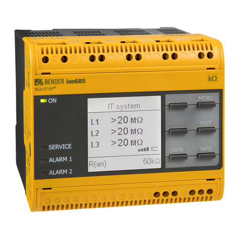
If the reading is below the selected response values Alarm 1/Alarm 2, the associated alarm relays re-
spond and the alarm LEDs „Alarm 1/2“ light up and the measuring value is indicated on the LC display
(in the event of DC insulation faults, the faulty supply line is indicated). If the terminals R1/R2 are brid-
ged (external RESET button [NC contact] or wire bridge), the fault indication will be stored. Pressing the
RESET button, resets the insulation fault message, provided that the currently displayed insulation resis-
tance is at least 25% above the actual response value when the reset is carried out. The fault memory
behaviour can also be set in the „ISO SETUP“ menu, by selecting the sub menu Memory: on/off.
The connections for an external kΩ display supplied by the current output 0(4)…20 mA at M+/M- are
galvanically isolated.
*) measuring principle (adaptive measuring pulse)
a measuring principle developed by Bender (European Patent: EP 0 654 673 B1).
Self test
A self test can be carried out manually using the TEST button or automatically. In order to guarantee
high functional reliability, the ISOMETER® IRDH275BM-7 provides comprehensive self test functions.
After switching the supply voltage on, all internal measuring functions, the components of the process
control such as data and parameter memory as well as the earth connections are checked using the self
test functions. The progress of the self test is indicated on the LC display by a bar graph. Depending on
the conditions in the IT system to be monitored, the self test is running for 15…20 seconds, then the
message „Test ok!“ appears on the LC display for approximately 2 seconds. Then the device returns to
the standard mode and the current measuring value is displayed after the expiry of the measuring time.
When a fault is found at the terminals and KE, the message „!Error!“ appears on the LC display, the
system fault LED lights up, the relay K2 (21-22-24) switches and the respective fault message (see table)
is indicated. If such a system fault occurs, a self test is started again every minute. If no more malfuncti-
on is detected, the fault message is deleted automatically and the system fault LED extinguishes.


