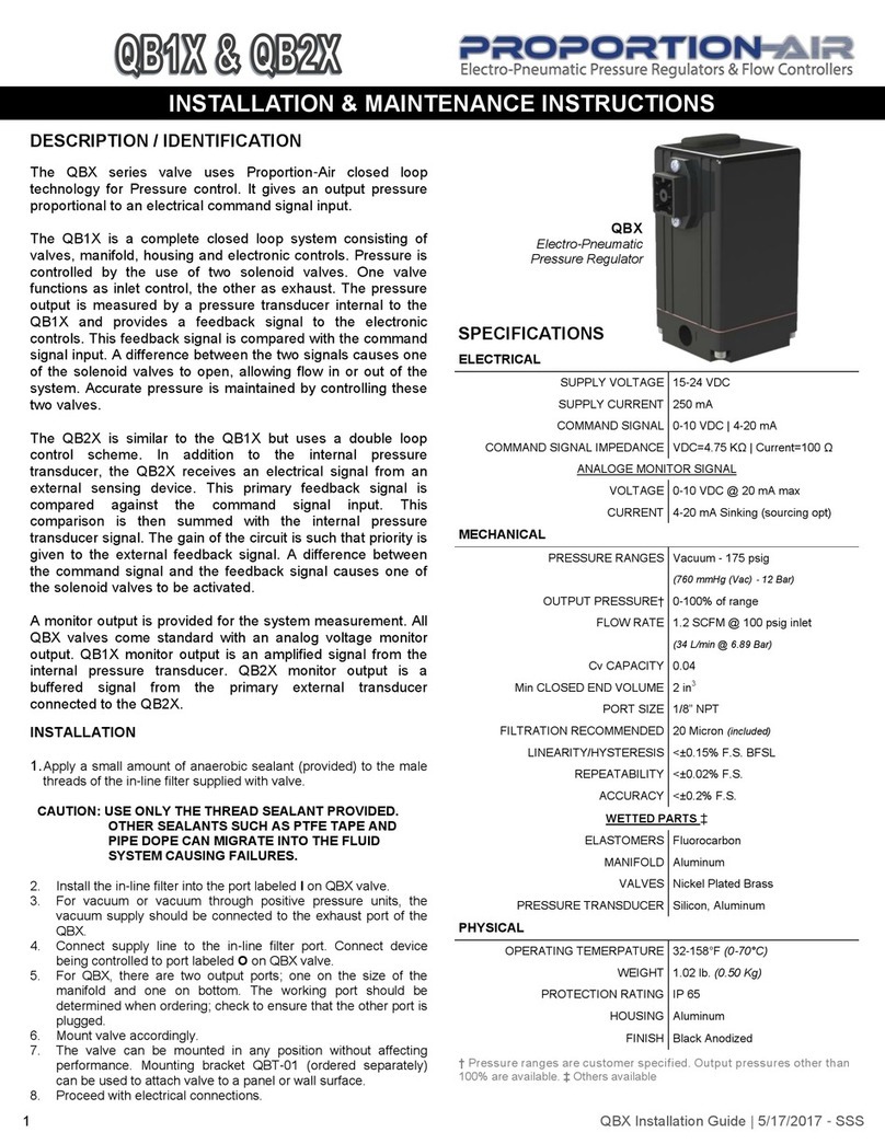
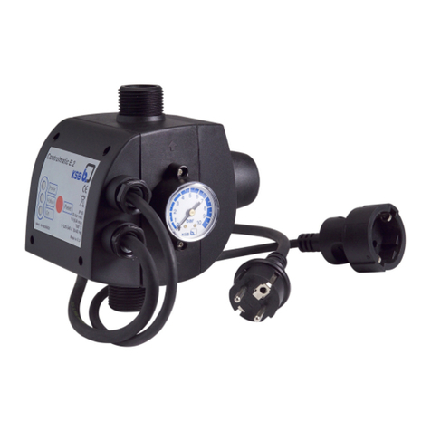
Proportion-Air QL3 Series Installation and operating instructions

1/4 INQL3-MAR09
03/03/09 WW
QL3 PRESSURE CONTROL VALVE
INSTALLATION & MAINTENANCE INSTRUCTIONS
SPECIFICATIONS
ELECTRICAL
SUPPLY VOLTAGE....................….15-24 VDC
SUPPLY CURRENT...................….250mA max.
COMMAND SIGNAL
VOLTAGE..................…..0-10 VDC
CURRENT..............…….4-20mA differential
COMMAND SIGNAL IMPEDANCE
VOLTAGE..................…..4.7 KΩ
CURRENT..................….100 Ω
ANALOG MONITOR SIGNAL
VOLTAGE...............…….0-10 VDC @ 10mA max
CURRENT……………….4-20mA Sinking or Sourcing
MECHANICAL
PRESSURE RANGES¹...............0 to 5 psig through 0-150 psig
OUTPUT PRESSURE¹................0-100% of range
FLOW RATE
FORWARD & EXHAUST .............25 SCFM max @ 120 psig inlet &
100 psig outlet
(708L/min @ 8.27 BAR inlet & 6.89
Bar outlet)
MIN. CLOSED END VOLUME.…..5 in³
FILTRATION RECOMMENDED…40 micron actual
LINEARITY………………...........…<±0.3% F.S. BFSL ²
HYSTERESIS……………………….0.05% F.S.
ACCURACY ..............................……<±0.4% F.S. ²
RESOLUTION………………………0.05% F.S.
WETTED PARTS‡ .................Elastomers - Buna N (3)
Manifold - Aluminum Nickel Plated
Valves - 430FR SS, 360 Brass
Seal material: Viton & Buna-N
P.Transducer - Utem 1000, Aluminum,
PHYSICAL
OPERATING TEMPERATURE....32-158ºF [0-70ºC]
DIMENSIONS…………………….2in.X2 in.X4.4 IN
(51mmX51mmX111mm)
WEIGHT.................................…....1.06 lb [0.50 Kg]
PROTECTION RATING...........…NEMA 4 / IP65
HOUSING...............................……Aluminum (Anodized)
VOLUME BOOSTER.....................Electroless Nickel Plate
¹ Pressure ranges are customer specified. Custom pressure ranges are avail-
able. Any range 5 to 150.
² Dependent on response adjustments. Valve can be field adjusted for best
response for the actual application
³ Other elastomers are available. Consult factory.
DESCRIPTION
The QL3 is a closed loop electronic pressure regulator consist-
ing of two solenoid valves, an internal pressure transducer, and an
electronic control circuit integrally mounted to a unique volume
booster. The output pressure is proportional to an electrical input
(command signal). The pressure is controlled by activating the
solenoid valves, which apply pressure to the pilot side of the vol-
ume booster. One valve functions as inlet control, the other as
exhaust. The output pressure of the volume booster is measured
by a pressure transducer, which is internally mounted and pro-
vides a feedback signal to the electronic control circuit. This feed-
back signal is compared against the command signal input. Any
differences between the command signal and the pressure feed-
back signal causes one of the solenoid valves to open to adjust the
pressure in the pilot of the volume booster. Pilot pressure is ad-
justed so that desired output pressure is achieved and maintained.
Since it is the actual desired work pressure that is being sensed
and fed back to the control circuit, any mechanical hysteresis of
the air piloted volume booster is automatically compensated for.
This allows for our extraordinary accuracy and repeatability.
The QL3 improves and builds on the proven Proportion-Air
QB3 series high performance by using a current driven variable
orifice solenoid valve and a unique analog PID circuit. This vari-
able orifice solenoid avoids the pressure “steps” prevalent in most
feed and bleed I/P’s. The PID circuit integrates error out quickly
resulting in superior resolution. The combination of a stepless
solenoid valve with a high speed analog PID on a high flow vol-
ume booster allows lots of air to be moved in a hurry, but pre-
cisely.
Command inputs come in a choice of either a 0-10 Vdc or 4-20
mA. The QL3 also provides an electrical monitor signal for out-
put to a panel meter or controller for data acquisition or quality
assurance needs. The monitor signal comes from the internal pres-
sure transducer. All QL3’s come standard with a 0-10 volt moni-
tor signal with 4-20 mA optional. Providing this monitor signal
as part of our standard package eliminates the need to purchase a
separate transducer.
The uniqueness of the volume booster design is that it has no
stamped gaskets or special molded diaphragm or seal parts. All
of the parts related to normal maintenance are standard o-rings.
Complete repair kits are available, but in case emergency repair is
needed parts should be available from any fluid power distributor
or even most neighborhood hardware stores. Since all sealing
parts are o-rings a large variety of chemical compounds are read-
ily available. You can select the compounds, which are most
ideally suited to your process and environment.
The QL3 is used for pressures up to 150 psig. For pressure
ranges between 150 and 500 psig, see the Proportion-Air QB3H
series.
Before you get started, please read these warnings:
♦ Examine the product. Ensure that you received what
you ordered.
♦ Read this guide first before you start and save it for
later use.
♦ You must have a good understanding of what the ad-
justments are on this product before using them.
♦ All compressed air and power should be shut off before
installing, removing or performing maintenance on this
product.
♦ Installation and use of this product should be under the
supervision and control of properly qualified personnel
in order to avoid the risk of injury or death.
Courtesy of CMA/Flodyne/Hydradyne ▪Motion Control ▪Hydraulic ▪Pneumatic ▪Electrical ▪Mechanical ▪(800) 426-5480 ▪www.cmafh.com

2/4 INQL3-MAR09
03/03/09 WW
Pneumatic Connections
CAUTION: USE ONLY THE THREAD SEALANT
PROVIDED. OTHER SEALANTS SUCH AS PTFE
TAPE AND PTFE PASTE CAN MIGRATE INTO THE
FLUID SYSTEM CAUSING FAILURES.
1. The valve can be mounted in any position without af-
fecting performance. A variety of mounting brackets
(QBT-01, QBT-02, and QBT-03. SEE ordering info)
can be used to attach valve to a panel or wall surface.
2. A typical 40 micron in-line filter is recommended on
the inlet of the QL3 valve. This is available from Pro-
portion-Air as part number FPP-2.
3. A 1/16” plug is supplied with the valve. It can be used
to plug the “Alternate Exhaust Port” if the exhaust
media should be captured or when the valve is used for
vacuum or vacuum through positive pressure control.
See Figure 1 for port location.
Positive Pressure Units
1. Connect supply pressure to the “I” port (Figure 1) not
to exceed rated supply pressure. (See TABLE 1)
2. Connect the outlet “O” port (Figure 1) to the device
being controlled.
3. The “E” exhaust port can be plumbed to a point out-
side the work area, fitted with a muffler or left open to
atmosphere as the application dictates.
4. Proceed with electrical connection.
CONNECTION PROCEDURE
Electrical Connections
1. Turn off all power before making electrical connec-
tions.
2. Identify the valve’s command input and analog output
using the calibration card included in the package and
the ordering information section on the last page of
this sheet.
3. Proceed to the appropriate section corresponding to the
type of valve being installed.
NOTE: ALL COLOR CODES RELATE TO QL3'S
ORDERED FROM THE FACTORY WITH PRE-
ASSEMBLED QBT-C-X CABLES.
Voltage Command Valves (TFEE)
All voltage command QB3's use a single ended command, mean-
ing the DC Common serves as both the power and command
common.
Current Command Valves (TFIE)
All current command QL3's use a differential current loop scheme
(not isolated), meaning current flow is from Pin 4 to Pin 2 on the
QL3 valve. Some applications may require the common of the
power supply that provides loop power for the 4-20mA command
to be tied to power supply common. The following diagram
shows the correct connection for conventional current flow.
PIN 2 {BLUE}
4-20MA COMMAND (-) PIN 4 {WHITE}
4-20MA COMMAND (+)
PIN 1 {GREEN}
DC COMMON (-)
PIN 6 {BLACK}
DC POWER (+)
PIN 4 {WHITE}
0-10 Vdc COMMAND (+)
PIN 1 {GREEN}
DC COMMON (-)
PIN 6 {BLACK}
DC POWER (+)
POWER AND
COMMAND
Current Monitor Valves
(TFEC or TFIC SINKING OUTPUT)
Use the following wiring diagram for QL3 valves with a current
sinking monitor output.
-
+
PIN 6 {BLACK}
DC POWER (+)
PIN 5 {RED}
4-20mA MONITOR (-)
MA
METER
Voltage Monitor Valves
(TFEE or TFIE)
Use the following wiring diagram for QL3 valves with a voltage
monitor output.
PIN 1 {GREEN}
DC COMMON (-) -
+
PIN 5 {RED}
0-10V MONITOR (+)
V METER
PIN 6 {BLACK}
DC POWER (+)
Current Monitor Valves
(TFES or TFIS SOURCING OUTPUT)
Use the following wiring diagram for QL3 valves with a current
sourcing monitor output.
-
+
MA
PIN 1 {GREEN}
DC COMMON (-)
METER
PIN 5 {RED}
SIGNAL OUT
Courtesy of CMA/Flodyne/Hydradyne ▪Motion Control ▪Hydraulic ▪Pneumatic ▪Electrical ▪Mechanical ▪(800) 426-5480 ▪www.cmafh.com

3/4 INQL3-MAR09
03/03/09 WW
RE-CALIBRATION PROCEDURE :
All QL3 control valves come calibrated from the factory by
trained personnel using precision calibration equipment.
The QL3 valve is a closed loop control valve using a preci-
sion electronic pressure sensor. Typical drift is less than
1% over the life of the product. If your QL3 valve appears
to be out of calibration by more than 1%, it is not likely to
be the QL3. Check the system for plumbing leakage, wir-
ing and electronic signal levels. Verify the accuracy of
your measuring equipment before re-calibrating. Consult
factory if you have any questions or require assistance.
For valves ordered with MAX. calibrated pressure Max. inlet pressure
5 through 10 psi positive 15 psig (1 bar)
10.1 up to 30 psig (0.70 up to 2 bar) 35 psig (2.4 bar)
31 up to 100 psig (2.1 up to 7 bar) 110 psig (7.6 bar)
101 up to 150 psig (7 up to 10.3 bar) 165 psig (11.4 bar)
RATED INLET PRESSURE FOR STANDARD QB3 VALVES
TABLE 1
Calibration
Access Cap
Figure 2
I
E
O
OUTLET
To Application
EXHAUST
INLET
Figure 1
Alternate Exhaust Port
Courtesy of CMA/Flodyne/Hydradyne ▪Motion Control ▪Hydraulic ▪Pneumatic ▪Electrical ▪Mechanical ▪(800) 426-5480 ▪www.cmafh.com

4/4 INQL3-MAR09
03/03/09 WW
PROPORTION-AIR, INC. BOX 218 MCCORDSVILLE, IN USA 46055
PHONE: (317)335-2602 FAX: (317)335-3853
INTERNET – www.proportionair.com E-MAIL – info@proportionair.com
Proportion-Air products are warranted to the original purchaser only against defects in material or workmanship for one (1) year from the date of manufac-
ture. The extent of Proportion-Air's liability under this warranty is limited to repair or replacement of the defective unit at Proportion-Air's option. Pro-
portion-Air shall have no liability under this warranty where improper installation or filtration occurred.
All specifications are subject to change without notice. THIS WARRANTY IS GIVEN IN LIEU OF, AND BUYER HEREBY EXPRESSLY
WAIVES, WARRANTIES OR LIABILITIES, EXPRESSED, IMPLIED OR STATUTORY, INCLUDING WITHOUT LIMITATION ANY
OBLIGATION OF PROPORTION-AIR WITH REGARD TO CONSEQUENTIAL DAMAGES, WARRANTIES OF MERCHANTABILITY,
DESCRIPTION, AND FITNESS FOR A PARTICULAR PURPOSE.
............................................................................................................................................................................................................
WARNING: Installation and use of this product should be under the supervision and control of properly qualified personnel in order to avoid the risk of
injury or death.
ORDERING INFORMATION
QL 3 T F E E xxx A Ø 8
SERIES SIZE
3 = 1/4” NPT Ports
CONTAINER
COMMAND
INPUT
MONITOR
SIGNAL
MAXIMUM
CALIBRATED
RANGE
5-150 psig*
EXAMPLES
100 = 0-100 PSI
* Check special options
for Pressure ranges not
starting at “0” psig .
E = 0-10 VDC
I = 4-20 MA
T = IMPACT ALUM.
E = 0-10VDC
C = 4-20 MA Sinking
S = 4-20MA Sourcing
PRE-ASSEMBLED POWER CORD
QBT-C-6
Length in feet (Other length are
available from 1 to 25 feet)
QB3 CONTROL VALVE
DIMENSIONS in (mm)
MONITOR
NOTES:
1.) ALL PORTS 1/4-18 NPT
(except alternate exhaust)
MOUNTING BRACKET
QBT-01 QBT-02
40 MICRON FILTER 1/4
NPT(Recommended)
FPP-2
QBT-03
FACTORY SET-
TINGS BASED
ON YOUR
APPLICATION
PARAMETERS
Courtesy of CMA/Flodyne/Hydradyne ▪Motion Control ▪Hydraulic ▪Pneumatic ▪Electrical ▪Mechanical ▪(800) 426-5480 ▪www.cmafh.com
Table of contents
Other Proportion-Air Control Unit manuals
Popular Control Unit manuals by other brands
MG
MG R3-CT4B instruction manual

Trenz Electronic
Trenz Electronic TE0712 TRM manual
Westinghouse
Westinghouse 7880040 Installation and operating instructions

Samson
Samson 41-23 Series Mounting and operating instructions
Armstrong
Armstrong GD-30 instructions

Leviton
Leviton GreenMAX RPM00-100 installation manual
