Denison Hydraulics 9-UK-22071-C User manual

1
Publ. 9-UK-22071-C replaces 9-UK 22071-B
DENISON HYDRAULICS
Multi-Function Proportional Valve
Dual Driver ( Encapsulated )

2
Multi-Function Proportional Valve Dual Driver ( Encapsulated )
Product Compatibility:
Introduction: Denison Hydraulics Have Long Recognised the Need for Driver Electronics Which Are Reasonably
Priced, Easy to Apply, Mechanically Sound and Can Be Utilised in Many Differing Environments and
With a Wide Range of Proportional Products.
The Ideal Is to Keep Product Variation to a Minimum Which Will Reduce Spares Stocking As Well As
Allowing Commissioning Engineers, System Designers and Machine Operators to Become Familiar
With a Limited Range of Connections and Adjustments Which Will Improve Overall Efficiency,
Confidence in the Electronic and Hydraulic Components and Once Comfortable With the Operation
and Parameters, Will Generate Proven Electro-Hydraulic ‘Building-Blocks’ Which Can Be Used Time
and Time Again Without Extra Design or Production Time Being Wasted on Learning a New Product.
The following ‘Application Hints’ for this versatile range of Dual Driver units are only issued as a guide
and if required, further help and /or advice should be sought from your Local distributor or from
Denison Hydraulics internal sales departments.
027-22071-0 ‘Encapsulated ( IP68 ) Printed Circuit Board ( PCB ).
• Mobile applications where ‘Externally’, Internaly’ or ‘Cab’ mounted .
• ‘Outdor’ applications.
• Aggressive environmental applications
• Marine usage ( when mounted in suitable sealed housing )
• Applications where humidity is a factor.
This Dual Driver uses the latest internal component and circuit design technology to give full CE
compliance to present EMC directives to ensure maximum operational potential and efficiency, while
offering Multiple supply voltages, command and valve current options ( all selected by internal PCB
mounted links ) in ONE unique and easy to apply package.
Note: ‘Encapsulated’ means the main Printed circuit board is totally encased in a black flame proof
resin which is impervious to external matter such as liquids e.t.c.
Valve
Type
Design
Letter
Coil
Voltage
Unit Supply
Voltage
Link
‘F’
Links
‘A’ & ‘B’
4DP01 A 12V 12V ( ± 10% ) F2 A3 & B3
4DP01 A 24V 24V ( ± 20% ) F2 A4 & B4
4DP01 B 12V 12V ( ± 10% ) F3 A3 & B3
4DP01 B 24V 24V ( ± 20% ) F3 A4 & B4
4DP02 A 12V 12V ( ± 10% ) F1 A3 & B3
4DP02 A 24V 24V ( ± 20% ) F1 A4 & B4
4DP02 single sol B 12V 12V ( ± 10% ) F2 A3 & B3
4DP02 double sol B 12V 12V ( ± 10% ) F1 A3 & B3
4DP03 A 12V 12V ( ± 10% ) F2 A3 & B3
4DP03 A 24V 24V ( ± 20% ) F1 A4 & B4
3DP03 A 12V 12V ( ± 10% ) F2 A3 & B3
3DP03 A 24V 24V ( ± 20% ) F2 A4 & B4
3DP06 A 12V 12V ( ± 10% ) F2 A3 & B3
3DP06 A 24V 24V ( ± 20% ) F2 A4 & B4
4DP06 A 12V 12V ( ± 10% ) F2 A3 & B3
4DP06 A 24V 24V ( ± 20% ) F1 A4 & B3
4RP01 A 12V 12V ( ± 10% ) F2 A3 & B3
4RP01 A 24V 24V ( ± 20% ) F2 A4 & B4
4RP01 D 12V 12V ( ± 10% ) F3 A3 & B3
4RP01 D 24V 24V ( ± 20% ) F2 A4 & B4
9A A 12V 12V ( ± 10% ) F2 A1 & B1
9A A 24V 24V ( ± 20% ) F2 A2 & B2
F5C A 12V 12V ( ± 10% ) F1 A1 or B1
VP01 A 24V 24V ( ± 20% ) F2 A4 or B4
VP01 B 12V 12V ( ± 10% ) F3 A3 or B3
VP01 B 24V 24V ( ± 20% ) F3 A4 or B4

3
Multi-Function Proportional Valve Dual Driver ( Encapsulated )
9Take a few minutes to FULLY read THESE information / data sheets BEFORE starting.
9Make sure the unit supply voltage is the same as the coils on the valve being driven !
9Ensure that you are aware of the available adjustments on the electronics and hydraulics.
9Make sure you have the correct tools to do the intended job ( i.e. D.V.M. ) e.t.c.
9‘Isolate’ this unit from all other equipment BEFORE any form of welding takes place.
9Check ALL connections to and from this unit to ensure NO short circuits.
9‘Start’ operating a new system at LOW pressure and with SMALL command signals.
9Check the units supply voltage is CORRECT, ‘ ELECTRICALLY CLEAN ’ and STABLE.
9Operate the units within specified operating temperature for best & reliable performance.
9Ensure that any unused wires / terminals are terminated safely and not shorted together.
9Contact DENISON Hydraulics for more information if you are unsure of connecting this unit.
9Fit the supplied rubber gasket correctly between valve coil and plug top driver unit.
9Keep High Voltage AC cables separate from Low Voltage DC signal and supply cables.
9Follow the set-up procedures in this manual for best operational results.
ALWAYS
NEVER
8Arc Weld or Charge Batteries with this driver unit connected as damage can occur.
8Attempt to use this unit if you are unsure of connections or expected operation.
8Attempt to use this unit in Areas where AC or DC coils HAVE NOT been fully suppressed.
8Use a power supply that is not rated for the correct required O/P current under full load.
8Allow wires TO or FROM the unit to short circuit ( to each other or chassis/cabinet e.t.c. ).
8Attempt to use this unit in areas of intense RF without adequate screening measures.
8Disconnect or connect wires to or from this unit unless it it isolated from the power supply.
8Use this unit in temperatures that exceed those specified as operation may be effected.
Important Notes:
Product Advantages: Fully EMC compliant product status to EN50081-1 and EN50082-2 ( heavy industrial spec. )
2 x dual proportional protected MosFet driver outputs ( PWM ) at upto 3 amps ( @12V ) each.
Unit comprises of field and time tested and proved electronic circuit design.
No extra DIN housing or ‘Card Holder’ to buy.
High level of product integrity maintained under extreme operational environments.
Remote ‘Enable’ OR ‘Emergency Stop’ input for maximum system safety.
Fully ‘Isolated’ product design for improved safety and ease of application difficult areas.
Internally generated +/- voltages for immediate connection to external/ remote 10K joystick or pot.
Unrivaled Industry leading ‘Linear’ Input / Output electrical characteristic for this type of unit.
Unique, Small compact size, light weight unit with ‘Blend-Anywhere’ colour.
Front panel full unit status ‘Diagnostic’ LED display
Able to drive many different proportional products with ONE unit giving reduced inventory.
Very Low cost compared to DIN cards and other available modules with comparative functions.
Easy to use front panel adjustments for all major parameters.
‘Digital’ & visual signal output of ‘mA Loop Failure’ for indication and remote system shutdown.
Separate Linear characteristic Ramp ‘UP’ and Ramp ‘Down’ adjustments.
Separate ‘I Min’ and ‘I Max’ adjustments for each solenoid.
‘Ruggedised’ internal & external design allowing use on ‘Internal’ OR ‘External’ applications.
Heavy duty ‘Two-Part’ polarised screw terminal connectors for easy application and use.
User configurable ( by Links ) for 12V or 24V supply input.
User choice of command input signal ( by Links ) from 0 to +/-5V, 0 to +/-10V or o to +/-20mA.
User definable ( by Links ) ‘Dither’ frequency ( 100Hz, 140Hz & 250 Hz )
‘Bulkhead’, wall or panel mounting, rust proof, high impact absorbing ABS molded enclosure.
Easy and secure mounting via 3 x 5mm fixings.
Flame proof resin encapsulation.
Protected inputs and user outputs for maximum reliability and product life.
Range of ‘Add-On’ option sub-boards to enhance base characteristics.

4
Multi-Function Proportional Valve Dual Driver ( Encapsulated )
• Single or Dual coil proportional pressure , flow or screw-in cartridge control valves.
• Mobile applications where ‘Chassis’ or externally mounted.
• Hostile environments.
• High Vibration and /or ‘G’ force applications.
• High Humidity applications.
• Marine usage.
• System load / Unload valves.
• Pump stroker ( single or dual sided operation )
• System building applications.
• Cost conscious applications.
Application Areas:
Manual Notes:
Denison Hydraulics prides itself on the fact that the product we supply to you is of outstanding quality that can
be applied easily and quickly with success but it is important for us to also understand changing customer
needs, market trends and application requirements. With this in mind, we will be only too glad to discuss new
applications and listen to new requirements that we can include in our future product designs, and use these
idea’s to improve still further the products usability and application flexibility.
This ‘Dual Driver’ have been designed to not only comply with required ‘CE’ legislation but in many areas,
exceed the test specifications demanded by the ‘EMC directives currently available as of February 1997. The
units will however only meet the specifications laid down in en-50081-1 & en-50082-2 ( heavy industrial
specification ) if they are connected in accordance with the relative ‘application data sheets’ supplied in this
booklet.
Denison Hydraulics have engineered this range of proportional valve drivers to meet today's exacting industry
needs. The units can, because of their unique design and array of built in options, be applied in market areas
ranging from marine to mobile with the confidence that our valve, vane and piston product lines already enjoy.
This ‘Dual Driver’ module is a culmination of many years field experience and are based on application ideas that
have come from all the various walks of industry that are already using Electro-hydraulic equipment. These
self contained units consist of all the necessary building blocks which will allow Electro-hydraulic system
designers to fully explore the advantages of proportional product whether mounted on a pump or as a means of
controlling pressure or flow. And to see quickly and effectively how we can say that DENISON hydraulics do
have :- ‘ Active Solutions to Dynamic Problems ’.
The information contained in this literature brochure is intended as a Guide Only. Installation and application of
either electronic or hydraulic product supplied by DENISON hydraulics, should only be undertaken by competent
personnel with a good understanding of Electro-hydraulic systems as well as being able to comply with all of the
required industry standards and working practices.
Denison Hydraulics reserve the right to alter, modify, up-issue and improve this products design, specification
and performance to meet new legislation, EC directive requirements and changing application areas without
giving prior notice.
While these units are ‘CE’ marked to show compliance with E.M.C. Directives, further advice on matters
pertaining to ‘CE’ marking of systems and equipment can be obtained from the D.T.I. Who have a specific
‘Hotline’ set up to deal with these matters.
With the supply of this literature and it’s contents, every effort has been made by DENISON hydraulics U.K. To
show due diligence and to offer as much advice as possible on application of the product such that it will comply
with the relative EC directives , however, it is the purchasers responsibility to ensure that a copy of this literature
is available to the nominated competent personnel who are assembling the equipment on their behalf so that the
‘application data sheets’ and their contained information can be followed and adhered to.

5
Multi-Function Proportional Valve Dual Driver ( Encapsulated )
Controller
Operation:
The Dual Driver unit 027-22071-0 is designed to operate continuously in any environment from a single polarity
+12VDC ( +/-10%) OR +24VDC ( +/-20%) supply voltage. Choice of the supply input voltage is made when selecting
the output current for the valve(s) being driven at links ‘A’ and ‘B’.
The driver use the latest ‘MosFet’ type output stage with ‘Current Feedback’ to ensure accurate efficient operation and
on the proportional valve, give an unrivaled linear output characteristic relative to a linear command voltage. Due to
the current feedback sensing circuit, each valve coil MUST be individually connected using separate cables and
NONE of these wires should be connected to Earth, 0V or shared with any other valve driver or coil.
The output driver is ‘Normally Off’ but on application of a command signal, uses Pulse Width Modulation ( PWM )
which, when set at the required frequency using the ‘F’ links, ( See ‘Link Options Data Sheet’ later in this brochure for
further information ) to suit the type and size of valve being driven, also provides the necessary ‘Dither’ signal to
ensure that the valves operation is not impaired by ‘ Stiction ’ and that the mechanical ‘ Hysterisis ’ is kept to a
minimum ( see Valve data sheet for ‘Dither’ frequency recommendation ).
The Proportional output drive from this unit is capable of driving a ‘Double Solenoid’ valve in a ‘Push-Push’
configuration where only ONE of the two solenoids per valve can ever be energised at any one time with the circuit
configured internally such that a positive (+) voltage command will energise the ‘A’ output drive while a negative (-)
voltage command will operate the ‘B’ output driver OR a ‘Single Solenoid’ valve normally connected to output ‘A’ and
reacting to a positive (+) command signal.
The valves start point ( Minimum ) is set by ‘I Min’ while the end point ( maximum ) is set by ‘I Max’ for each
individual coil by the potentiometers on the front panel. The minimum output value ( I Min ) will only be seen on the
respective output drive AFTER an internally set Comparitor Detection Circuit ( described below ) has been
exceeded by the incoming command signal.
The ‘I Min’ A & B and’ I Max’ A & B adjustments are CLOCKWISE to INCREASE the relative channels output
current and ANTI-CLOCKWISE to DECREASE the output current with all four potentiometers being approx. 20 turn
variety ( ±5 turns ) with mechanical end stop slipping clutches to protect them from over adjustment.
The Standard unit is supplied with the command type select ‘S’ link in a NULL STORAGE POSITION ( see page 22,
bottom right of page ) which defaults the Dual Driver to +/-5V command. This can by easily changed by altering the
links position to either S1, or S3, which configures the unit to accept 0 to +/-20mA OR 0 to ±10V command signals
respectively. The unit has an internally set Comparitor Detection Circuit which will ignore any command signal input
upto ±170mV ( Approx. for ±10V command ) and ±85mV ( Approx. for ±5V command ). This is done to ensure that
when zero drive is required, it can be achieved without the fear of ‘Electrical Noise’ on the command signal wires
causing an erroneous valve operation. This ‘Zero-Band’ also allows for mechanical tolerances and increasing
‘sloppiness’ in Joysticks or potentiometers at the zero position with age and usage.
The units Ramp Generator is of the linear variety, is imposed onto the command signal and is fully adjustable from
the front panel potentiometers in the range of 20mS to 10 Secs ( Approx.) The ‘UP’ slope adjustment effects any
signal going from a numerically smaller value to a Larger one ( i.e. +1V to +4V OR -1V to -4V ) In any quadrant, while
the ‘DOWN’ adjustment effects any signal going from Larger numeric value to a smaller one ( i.e. -4V to -1V OR +4V
to +1V ) again In any quadrant.
The ramp generator adjustments are CLOCKWISE to INCREASE rate of change of signal ( longer ramp time )and
ANTI-CLOCKWISE to DECREASE the rate of change of signal ( shorter ramp time ) with both potentiometers being
approx. 20 turn variety with mechanical end stop slipping clutches to protect them from over adjustment.
The Dual Driver controller 027-22071-0 has also been designed to accept a range of optional ‘Add-On’ sub boards
which locate onto two sets of vertical connector pins and are held mechanically in place by a single M3 plastic screw
( supplied with Sub-board ).
With the addition and fitting of any sub-board, the user should observe the details associated with the new option and
connect the Input / Output signals appropriately.

6
Multi-Function Proportional Valve Dual Driver ( Encapsulated )
Add-On Boards: There are several Add-On boards available to the user to alter the base drivers characteristics:-
027-22072-0:- 4-20mA command input board with safety alarm and override.
027-22073-0:- Voltage command signal summer and offset board.
027-22074-0:- Inductive joystick ( 2 axis ) signal interface conditioning board.
027-22075-0:- Electronic Horse power limiter board ( current transformer input ).
All of the above ‘Sub-boards’ are designed to fit onto the rear of a dual driver controller 027-22071-0 ONLY.
It should be noted that only ONE sub-board function per dual driver is possible.
027-22072-0 ‘4-20mA command’ input board.
This sub-board also has a built in ‘Loop Fault’ detector circuit which activates if the current loop input falls below
approx.. 3.7mA ( Industry Standard for current loop failure ). If this occurs, the command signal is immediately sent to
zero ( the output led’s ‘A’ & ‘B’ will immediately go ‘Off’ ) and is held there until the current loop goes above the 3.7mA
threshold when the driver will again *** start to follow the command. At the same time as the ‘Fault’ is detected, an
open collector transistor circuit is triggered and made available on terminals ‘T1’ & ‘T2’ which goes from a ‘HI’ level (
approx.. 8V with 3K3 pull-up ) to a ‘LO’ level ( approx. 0V ) on error. A front panel RED led on the Dual Driver base
unit also lights as a visual indicator of the problem to the operator.
*** It should be observed that if the 027-22072-0 sub-board is configured for Bi-Directional output and the current
command comes back ‘ON’ at 4mA after a fault, the valve driver will be commanded to drive fully in the ‘B’ coil
direction which may be a danger. It is therefore strongly recommended that the ‘Loop Fault’ detect circuit output is
made part of the control system such that if a fault occurs, the command is automatically sent to 12mA ( zero ) and
that the ‘Emergency Stop’ on the base Dual Driver unit is activated until the equipment is ensured to be safe for
operation.
027-22073-0 ‘Voltage Summing’ options board.
This Sub-board has been designed to allow simple voltage signal summation / subtraction and to allow the user to set
hydraulic ‘Offsets’ electrically for applications such as winches where a minimum tension may be required at a zero
command signal.
On-board links are provided to allow signal polarity to be set to give the required output command sense relative to the
voltages being conditioned.
027-22074-0 ‘ Inductive Joystick’ options board.
This option allows the user to interface with inductive joysticks from several manufacturers. There are provisions for
output gain settings to cater for differing mechanical movements
The one sub-board is also able to condition two channels from an ‘X’, ‘Y’ joystick and control 2 x dual driver controllers
to give a full system if required.
027-22075-0 ‘ Electronic Horse Power limiter’ options board.
Effective and cost effective HP limiting can be achieved with better accuracy and repeatability with this option
compared to standard mechanical versions.
The option also allows much lower HP to be set and controlled as well as offering remote setting and operation using
a normal 900 series pump stroker.
For added safety, the dual driver controllers have a separate ‘High Current’ input supply for the output stage.
This connection MUST be made for the unit to work and should normally be connected to the supply voltage via a
NORMALLY CLOSED ‘Emergency Stop’ switch. If this switch is opened, the output Immediately goes to zero, the
‘A’ or ‘B’ output On led’s on the front panel go ‘OFF’ and the front panel led marked as ‘Emergency Stop’ illuminates
*** ( this will only happen IF the other ‘Low Current’ supply input is connected and powered ).
*** If the valve has no command signal ( valve at zero position ) at the time of ‘Emergency Stop’ line being activated,
the front panel RED light may take a few seconds to illuminate fully. This is normal operation and is due to an internal
electrical noise filter circuit on the emergency stop input having to discharge before allowing the light to come on. If a
command is applied during this period, the light immediately illuminates and the valve is turned OFF.

7
Multi-Function Proportional Valve Dual Driver ( Encapsulated )
Initial Dry set-up
procedure:
1) Isolate electric motor drives to the hydraulic pumps.
2) Ensure that all connections conform with one of the suggested schematic diagrams shown in this manual.
3) Check that all connections are secure and NOT shorting together OR to the case OR any other equipment.
4) Ensure that ALL the links needed are fitted and configured to suit the required application, product and available signals.
5) Install a ‘Current meter’ in line with the ‘A’ output, set to a relative current range.
6) Make sure that ( If Fitted ) the ‘Emergency Stop’ switch is closed and connected to correct supply voltage.
6) Apply power ( +12V +/-10% OR +24V +/-20% ) to the unit and ensure that the ‘Power On’ light is on and bright.
8) Move the joystick or command potentiometer until Approx.. +10% of chosen configured command is achieved.
9) Set ‘I Min’ A to give Approx.10% of the valve products maximum drive current ( see valve literature ) on the relative meter.
10) Ensure that front panel indicator ‘Output A’ lights ( Dimly )
11) Move the joystick or command potentiometer until +100% of chosen configured command is achieved.
12) Set ‘I Max’ A give 100% of the valve products maximum drive current ( see valve literature ) on the relative meter.
13) Ensure that front panel indicator ‘Output A’ lights ( Brightly ).
14) Repeat steps 8) throe 13) until required Min & Max currents are reached for +10% and +100% command signal input.
15) Open ‘Emergency Stop’ switch and check that:- a) Active Outputs immediately go to zero mA.
b) ‘Emergency Stop’ front panel Indicator lights.
16) Set command signal to zero position.
17) Reset ‘Emergency Stop’ switch to closed position and ensure that ‘Emergency Stop’ Indicator light goes OUT.
18) Repeat steps 8) thro 17) using -10% and -100% command signal values and moving the current meter to the ‘B’ output.
Final ‘Live’
calibration
procedure
1) Ensure that ALL moving parts are guarded and personnel are aware of a ‘LIVE’ system run.
2) Ensure joystick or command potentiometer is at zero position with zero % command output.
3) Start hydraulic power pack and wait until constant speed / set pressure has been achieved.
4) Move the joystick or command potentiometer SLOWLY until Approx. +10% of chosen configured command is achieved.
5) Monitor hydraulic product being controlled and set ‘I Min’ A to give desired minimum flow or pressure.
6) Move the joystick or command potentiometer SLOWLY until +100% of chosen configured command is achieved.
7) Monitor hydraulic product being controlled and set ‘I Max’ A to give desired maximum flow or pressure.
8) Repeat steps 4) thro 7) until required minimum and maximum system flows are achieved for +10% and +100% command.
9) Set command signal to zero position.
10) Repeat steps 4) thro 7) using -10% and -100% command signal.
11) Set command signal to zero position.
Electrical
specifications:
1) Board Style: Denison Hydraulics Unique Size and Mounting.
2) Connector Type: Heavy Duty Two Part Polarised ‘Screw’ Type Terminal Connectors.
3) Input Supply Voltage(s): +10 - +32 VDC ( Max ) ( set supply volts the same as coil voltage )
4) Input Supply Current ( Max ): Maximum Valve Current Setting + 200mA Quiescent (Max)
5) User Output Voltages: +/- 5V D.C. ( +/- 5% ) Rated @ 5mA Per rail.
6) Command Input Type(s): D.C. Voltage and Current.
7) Command Input Value(s): +/-5V, +/-10V & 0 to +/-20mA
8) Available adjustments: I Min ‘A’, I Max ‘A’, I Min ‘B’, I Max ‘B’, Ramp UP, Ramp DOWN.
9) Ramp Type: Linear and Continuously Variable by 20 Turn ( +/- 5 Turns ) Potentiometers
10) Min Ramp Time UP: 20mS ( +/-20% )
11) Maximum Ramp Time UP: 10S ( +/-20% )
12) Min Ramp Time DOWN: 20mS ( +/-20% )
13) Minimum Ramp Time DOWN: 10S ( +/-20% )
14) Dither Frequencies : Link Selectable 100Hz, 140Hz, 240Hz ( All +/- 20% )
15) Environmental: ‘ENCAPSULATED’ Printed Circuit Board.
16) IP Rating for PCB Only: IP65 ( Without Being Mounted In External Enclosure )
17) IP rating for Housing: IP56 ( Due to user accessibility of connector screw terminals. )
18) Humidity: 90% Non Condensing.
19) Storage temp.: 80 Deg C ( Max )
20) Working temp.: 60 Deg C ( Max )

8
Multi-Function Proportional Valve Dual Driver ( Encapsulated )
Controller Block Diagram:
Ramp UP
Ramp Down
Generator
Input
Supply
protection
+/- Voltage
reference
generators
+12V / 24V Power Supply Input 1
3
4
0V Supply Input
System ‘Earth’ Input
5
6
7
+5V (+/-5%) @ 5mA User Output
Command Signal Input
-5V (+/-5%) @ 5mA User Output
8
0V Command Signal Input
2
+12V / 24V Valve
Supply Input
Heavy Current
Supply to
Output Stages
Ramp
UP
Ramp
DOWN
I Min ‘B’
I Max ‘B’
Current
Feedback
9
10
MosFet
Output
Stage ‘B’
Valve Coil
Connections
I Min ‘A’
I Max ‘A’
Current
Feedback
11
12
Valve Coil
Connections
To Output
Stages ‘A’ & ‘B’
Link ‘B1’ = 12V@800mA
Link ‘B2’ = 24V@500mA
Link ‘B3’ = 12V@2700mA
Link ‘B4’ = 24V@1700mA
MosFet
Output
Stage ‘A’
Link ‘A1’ = 12V@800mA
Link ‘A2’ = 24V@500mA
Link ‘A3’ = 12V@2700mA
Link ‘A4’ = 24V@1700mA
Link ‘S1’ = +/- 0 TO 20mA Input
NO LINK = +/- 0 to 5V DC Input
Link ‘S3’ = +/- 0 to 10V DC Input
+/-V Input
Conditioning
Circuits
Notes:-
1) Positive polarity (+) command ALWAYS controls output ‘A’.
2) Negative polarity (-) command ALWAYS controls output ‘B’.
3) Reduced supply voltage will result in a reduced output availability to the coil being controlled due to
circuit losses. To achieve maximum coil current ( if required for maximum pressure or flow ) ,
ensure that the supply voltage is at the upper supply limit as shown below:-
For 12V coils, use 12V +20% ( Approx. 13.8 – 14VDC )
For 24V coils, use 24V +20% ( Approx. 28 – 32VDC )
Link ‘F1’ = 100Hz
Link ‘F2’ = 140Hz
Link ‘F3’ = 250Hz
Dither
Frequency
Generator
9
Multi-Function Proportional Valve Dual Driver ( Encapsulated )
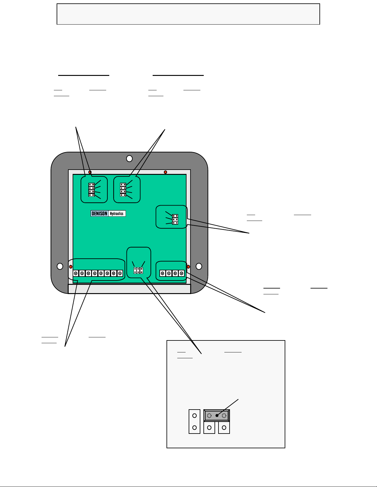
Link locator:
Unit Rear View With Lid
Removed
Function
+V DC Power Supply Input
+V DC Valve Supply Input
0V DC Power Input
System Earth Connection
+5V (+/-5%) @ 5mA User Output
-5V (+/-5%) @ 5mA User Output
Command Signal Input
Command Signal 0V (0V Sig)
Terminal
Number
1
2
3
4
5
6
7
8
----
----
----
----
----
----
----
----
Function
12V Coil @ 800mA
24V Coil @ 500mA
12V Coil @ 2700mA
24V Coil @ 1700mA
Link
Number
‘A 1’
‘A 2’
‘A 3’
‘A 4’
----
----
----
----
Valve Coil ‘A’
Function
12V Coil @ 800mA
24V Coil @ 500mA
12V Coil @ 2700mA
24V Coil @ 1700mA
Link
Number
‘B 1’
‘B 2’
‘B 3’
‘B 4’
----
----
----
----
Valve Coil ‘B’
+/- 0 to 20mA Command Input Option Select
+/- 5V DC Command Input Option select
+/- 10V Command Input Option select
Function
Link
Number
‘S 1’
NO LINK
‘S 3’
----
----
-
S1 S3
Selector link storage
position = +/- 5V I/P
command.
Function
Output ‘B’ +
Output ‘B’ -
Output ‘A’ +
Output ‘A’ -
Terminal
Number
9
10
11
12
----
----
----
----
B A
1
2
3
4
1
2
3
1 2 3 4 5 6 7 8 9 10 11 12
F
S
1 3
Function
100 Hz Dither Frequency Option select
140 Hz Dither Frequency Option Select
240 Hz Dither Frequency Option select
Link
Number
‘F 1’
‘F 2’
‘F 3’
----
----
-
1
2
3
4
1
2
3
4
1
2
3
1
2
3
4
Base unit will accept the following
command signals:-
Voltage:- 0 - 5V
Voltage:- 0 - +/- 5V,
Voltage:- 0 - 10V
Voltage:- 0 - +/- 10V
Current:- 0 – 20mA
Current:- 0 - +/- 20mA
10
Multi-Function Proportional Valve Dual Driver ( Encapsulated )
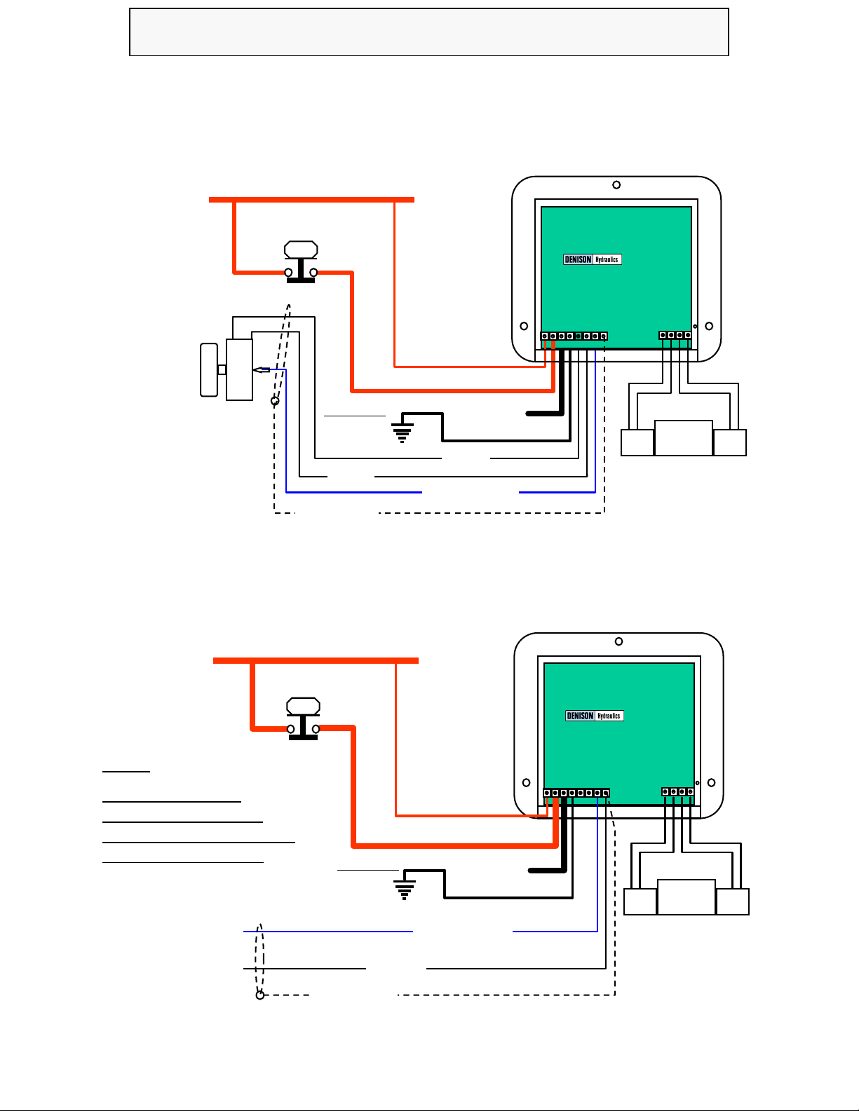
Potentiometer / Joystick
Connection example:
Unit Rear View With Lid Removed
0V Supply
Emergency ‘STOP’
Switch
Fit if required
for EMC
IMPORTANT
Command
Potentiometer
or Joystick
10K Ohm
( 12V @ 3 Amps )
+12 or 24 V
Supply
Low ‘Circuit’ Current Supply
Heavy ‘Valve’ Current Supply
( 24V @ 2 Amps )
Command Signal I/p
+5V User
-5V User
External command
Connection example:
Unit Rear View With Lid Removed
0V Supply
Emergency ‘STOP’
Switch
( 12 V @ 3 Amps )
+12 or 24 V
Supply
Low ‘Circuit’ Current Supply
Heavy ‘Valve’ Current Supply
Command Signal I/p
External command
Signal 0V
0V input
1 2 3 4 5 6 7 8
12 / 24 V
( 24V @ 2 Amps )
NOTE:-
Ensure that ‘External
Command’ source 0V is
connected to Dual Driver unit
0V for correct operation.
+/-
Fit if required
for EMC
IMPORTANT
12 / 24 V
9 10 11 12
1 2 3 4 5 6 7 8
9 10 11 12
Signal ‘SCREEN’
Signal ‘SCREEN’

11
Multi-Function Proportional Valve Dual Driver ( Encapsulated )
Single Coil
Connection
Information:
This information applies to all single coil applications:-
• Ensure that the supply voltage is the same as the coil voltage.
• Select the correct output current links on the Dual Driver unit for the valve coil.
• Connect valve coil to terminals 11 & 12 ( ‘A’ coil Output ) only.
• Connect the command potentiometer ( 10K ) between terminals 5 ( +5V ) and 8 ( 0V )
• Connect the command potentiometer wiper to terminal 7 ( Input )
This configuration ( using positive +5V reference voltage ) will only operate the ‘A’ output from the Dual driver unit, This
means that only the I Min and I Max ‘A’ will be needed to adjust the output current. This set-up will also maximise the
potentiometer electrical travel giving better resolution which means better control.
If an external command signal is used, select the correct ‘S’ link to suit and ensure that the 0V from the external signal
source is connected to terminal 8 ( 0V ) and that only a positive polarity signal is fed to the Dual Driver unit.
If for any reason the ‘B’ output is required to be used, simply remove the potentiometer wire from terminal 5 ( +5V ) and
re-connect to terminal 6 ( -5V ). This will also mean that I Min and I max ‘B’ now adjust the output current to the valve.
Dual Coil
Connection
Information:
This information applies to all Dual coil applications:-
• Ensure that the supply voltage is the same as the coils voltage.
• Select the correct output current links on the Dual Driver unit for the valve coil.
• Connect valve ‘A’ coil to terminals 11 & 12 ( ‘A’ coil Output ) only.
• Connect the valve ‘B’ coil to terminals 9 & 10 ( ‘B’ coil
• Connect the command potentiometer ( 10K )between terminals 5 ( +5V ) and 6 ( -5V )
• Connect the command potentiometer wiper to terminal 7 ( Input )
This configuration using the positive +5V and negative -5V reference voltages will operate the ‘A’ output from the +V
command and the ‘B’ output from the -V command. This means that the I Min and I Max ‘A’ will be needed to adjust the
‘A’ output current and the I Min and I Max ‘B’ will be needed to adjust the ‘B’ output current . This set-up will maximise
the potentiometer electrical travel giving better resolution which means better control.
Zero output to the valve coils will be when the command signal is at zero ( 0V ) or approx. mid travel of the potentiometer
being used.
If an external command signal is used, select the ‘S’ link to suit and ensure that the 0V from the external signal source is
connected to terminal 8 ( 0V ) and that a positive and negative polarity signal is able to be fed to the Dual Driver unit for
control of both coils.
•Proportional product starts with a large flow or pressure for a small command input.
1) Reduce the respective ‘I Min’ setting on the front panel.
•There is Not enough flow or pressure at maximum command input.
1) Increase the respective ‘I Max’ setting until the required levels are achieved.
2) Check that the correct Link selection for the command input have been made.
•Cannot achieve full flow or pressure at full command and full ‘I Max’ adjustment.
1) Check that the correct links for coil ‘A’ & ‘B’ current are selected.
2) Check supply voltage is fully 12 or 24V and is stable under load conditions.
3) Ensure that the coils fitted to the valve are correct for the supply voltage( I.e. 12 or 24V ).
•The ‘Emergency stop’ Red led is always lit and no output is available.
1) Ensure that there is voltage supply to terminal No. 2 ( Valve supply input ).
•The unit does not respond to an external command voltage.
1) Ensure that the external command source’s 0V is connected to the driver units 0V terminal.
2) Check continuity of command cables between source and driver unit.
•The output from the driver goes between zero and full on only with no proportionality.
1) Ensure that there is a coil connected to the output.
2) Check that the coil wires (2) are not shorted and correctly connected to the driver unit.
3) Check that the some of the wires to the two coils have NOT become transposed.
•There is no adjustment with the ‘I Max’ potentiometer possible.
1) Reduce the respective ‘I Min’ potentiometer setting as it is to high to get control with ‘I Max’.
•The unit has both outputs ‘A’ & ‘B’ on together.
1) Check that the command signal is not oscillating at a high frequency.
2) The unit is damaged and needs to be replaced.
•The unit is completely dead with no led’s on at all.
1) Check that the supply voltage is present & correct
2) Check the supply input fuse for continuity and correct fitting.
3) The unit is damaged and needs to be replaced.
•The unit is very slow to respond to command input signals.
1) Re-adjust the driver units ‘Ramp Generator’ settings to get required response.
•The Units output ‘flips’ over from ‘B’ output to ‘A’ output.
1) This characteristic is not a fault , it occurs ONLY on the negative command side and is because
the input command is well in excess ( approx. 50% higher ) of the option chosen.
It is caused by the internal semiconductor amplifiers being over-driven and folding back upon
themselves.
To avoid this mode of operation, Command signals should be accurately kept to the signal range selected and
not allowed to exceed these levels by greater than 2% maximum.
Trouble
shooting Guide
12
20
11-11-1998/22071_AA.ppt
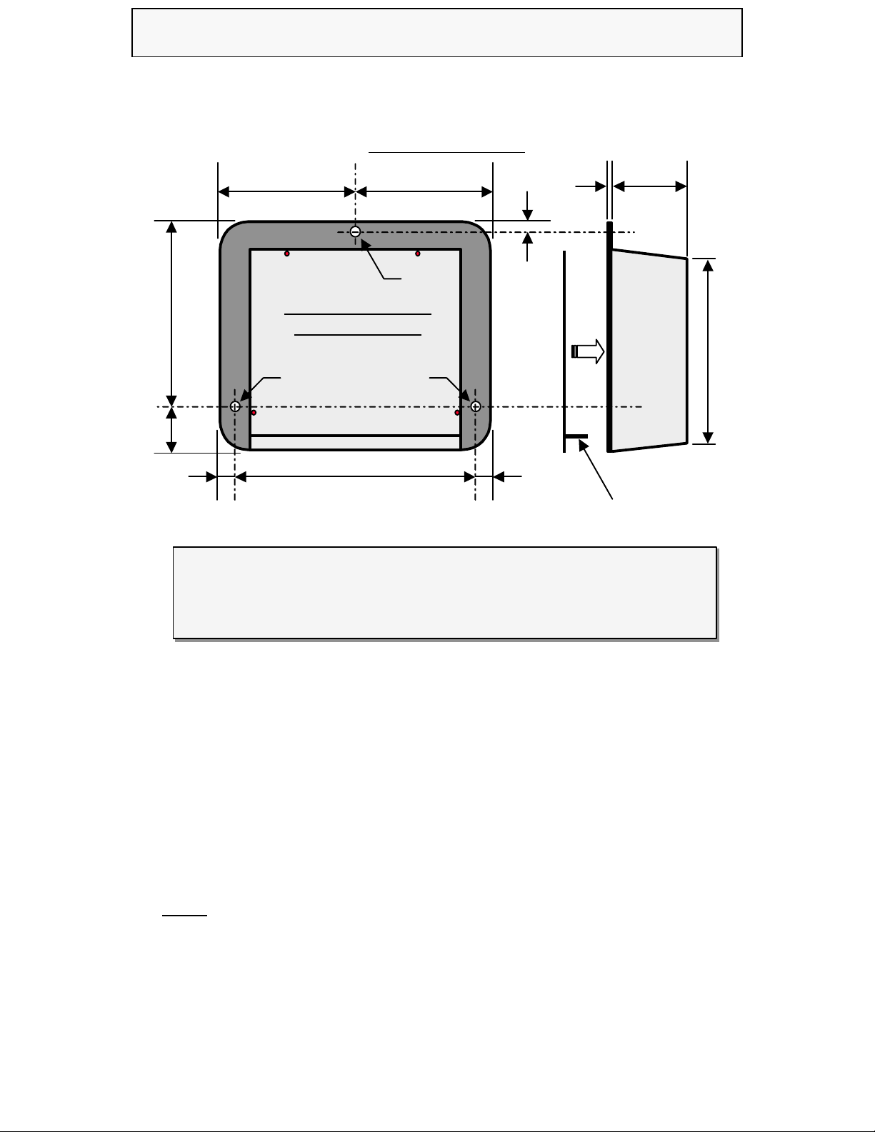
Housing Specification for Dual driver Units:-
027-22071-0
Housing Specification for Dual driver Units:-
027-22071-0
Housing Type:- ‘Flanged’ Bulkhead / Panel Mounting.
Housing Material:- High Impact Resistant Molded ABS.
Housing Colour:- Black.
Surface Finish:- Matt.
Housing Thickness:- 2mm ( Mounting Flange and Face ), 1.7mm All Internal Dividers.
Base Dimensions:- 112mm X 120mm.
Rear Panel:- Separate ‘Self Locking’ Rear Cover With.
Wire entry:- Via 7 X ‘Slots’ in rear panel support bar.
Encapsulation:- Flame Resistant, Black , Two Part Epoxy Resin.
NOTE:- Rear panel is ‘self-locking’ and comes in unit packaging and must be fitted by
user once adjustments have been completed.
View looking into rear
of Dual Driver unit.
Rear Panel Removed.
5mm
Dia.
5mm
Dia.
5mm
Dia.
6mm60 mm 60 mm
90 mm
22 mm
108 mm
6mm
6mm
2mm 40mm
95mm
Drawing NOT TO SCALE.
RearPanel(Removed)
Wire entry ‘slots’ in
Rear panel ‘Support bar’
Mechanical Data
This manual suits for next models
1
Table of contents
Popular Control Unit manuals by other brands


Johnson Controls
Johnson Controls VP140 installation guide

Amersham Pharmacia Biotech
Amersham Pharmacia Biotech INV-907 instructions

Land Pride
Land Pride 380-152A installation instructions

Honeywell
Honeywell FV300 Maintenance instructions

Spectrum Controls
Spectrum Controls Micro 800 user manual

Spirax Sarco
Spirax Sarco Colima FLU Series Installation and maintenance instructions

Leviton
Leviton LV200 user guide

M-system
M-system R3Y-SS8 instruction manual

Rockwell Automation
Rockwell Automation Allen-Bradley Guard I/O DeviceNet 1732DS-IB8 user manual

Rittal
Rittal SV9343.070 Assembly and operating instructions

Nera
Nera F55 Brief operating instruction

MX
MX Atmos Vision Fitting instructions