ProRacing TS2 PRO User manual
User Manual
TS2 PRO
Read before installation
Turbo petrol engines
2
1 Application and Photo montage
..........................................................................................................................
3
2 Proracing overview ............................................................................................................................ 4
4 Petrol Engines Assembly ............................................................................................................................. 7
5 First start-up .................................................................................................................................................. 11
6 Adjustment
.............................................................................................................................
............................................................................................................................. 12
7 Troubleshooting ............................................................................................................................... 14
7 Contact details .............................................................................................................................................. 18
Index
Overview and explanation of the symbols used
Warnings on dangers with important information on use. Please read!
General information on assembly and use.
Tips for easier assembly and use.
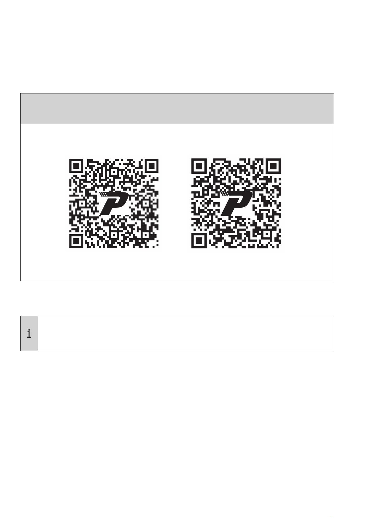
1 Applicazione per smartphone (optional)
Android APP iOS APP
Scarica l’app Proracing sul tuo Smartphone e scopri il nuovo piacere di guida.
Normalmente dopo l’acquisto, inviamo tramite mail le foto speciche per il tuo
motore per un montaggio semplice, controlla la mail.
Scansiona con la fotocamera del tuo smarthphone e verrai indirizzato automaticamente
all’app store.
3
4
A
B
C
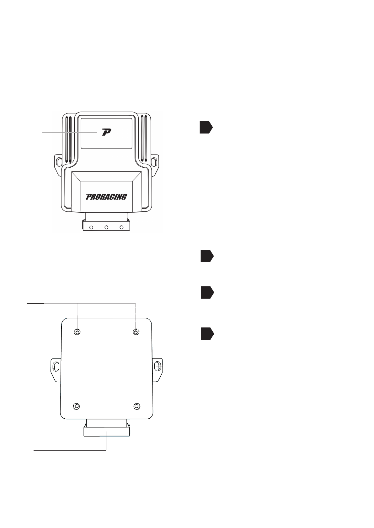
2 Panoramica di Proracing TS2 PRO
Luminous program interface
ECO: Blue color
SPORT: Green color
RACE: Red color
FCI socket connection for xing
of the Proracing TS2 PRO harness
Holes for closing the box opening (TORX)
D Holes for xing with cable ties.
A
D
C
B
5
3 Installation
Phase 1 of 6 - preparing the installation
Wait about 10 minutes before acting, in this way all the electrical equipment will be
deactivated.
•
•
•
•
•
1
2
Let the engine cool down before installing the Proracing ECU, you could burn yourself.
Open the bonnet and keep the doors locked.
Normally, no special tools are required for installation, a wire cutter is sucient to remove
the remains of the clamps. In some cases a torx key to open the control unit and change
to Bosch or Siemens / delphi.
With, Keyless Go or electronic key, be careful to keep the car key at a distance
about 10 meters from the car to be out of radio coverage.
In the event of an anti-theft device, it must be deactivated before starting the installation.
In some rare cases it is possible that the car with the hood open keeps the sensors
active, therefore it is advisable to disconnect the battery positive to avoid generating
an error.
If you have any questions or problems during installation, you can nd answers on
Error removal.
Our customer support is also available - You can open a Ticket
on our website.
6
A
B
3 Installation
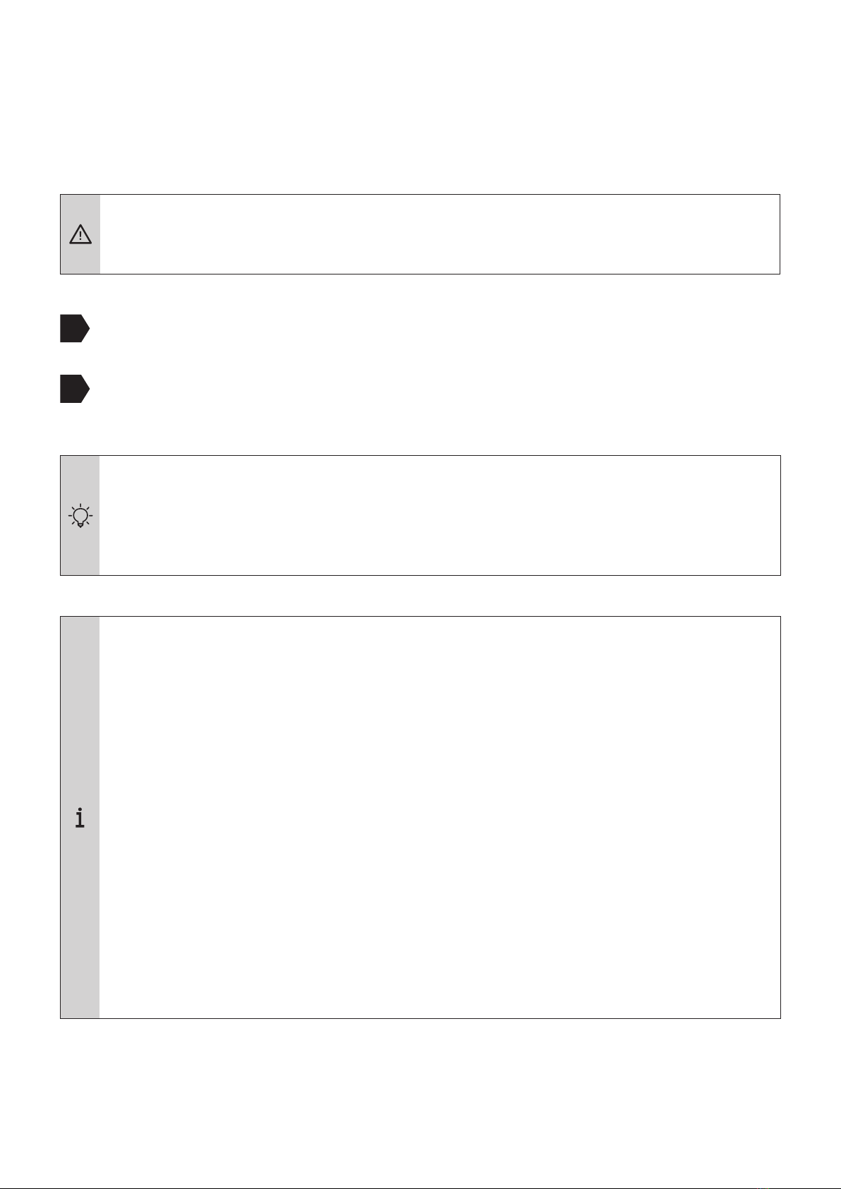
Step 2 of 6 - Remove the engine cover
•
•
•
Normally after purchase, we send specic photos for yours by email
engine for easy editing, then check your mail.
In the following images there will be sample photos. Your car may dier,
However, the installation is very similar.
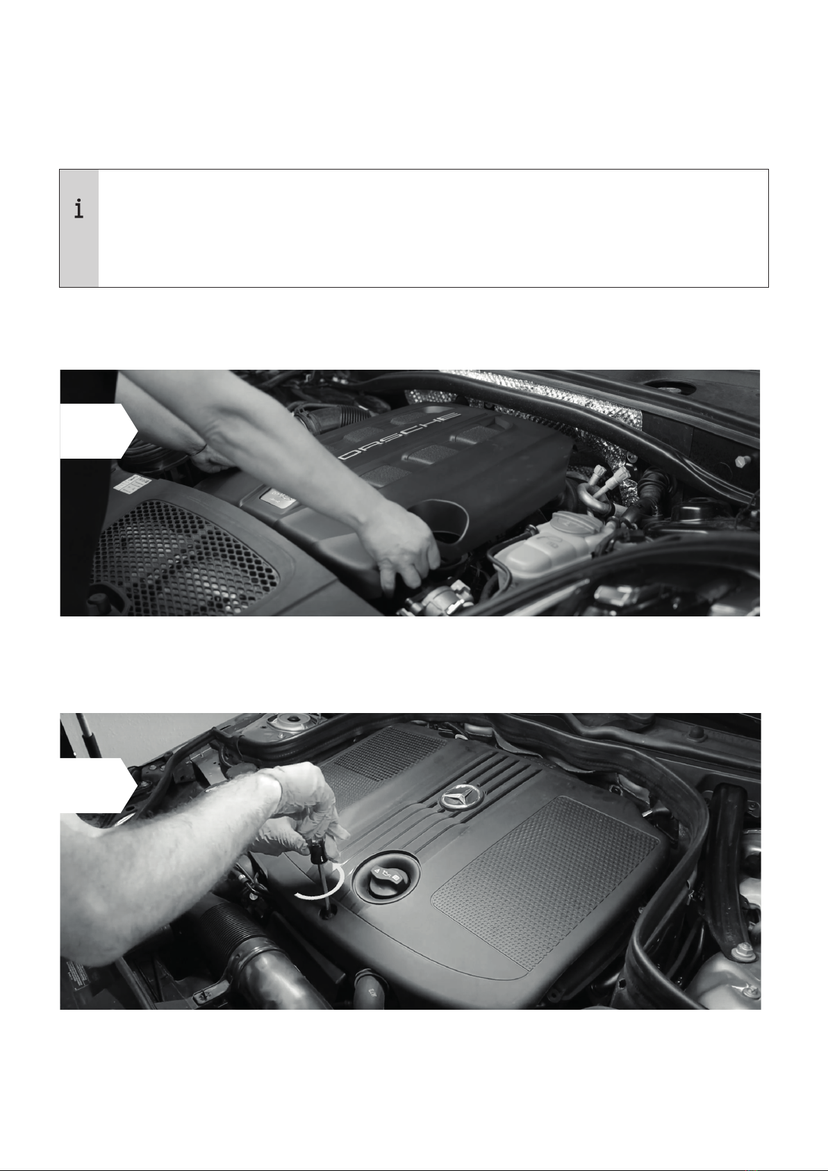
Normally your engine cover is interlocked with rubber clips (A) or
with one or more screws (B).
Remove the engine cover and set it aside, simply lift upwards by doing
more strength in one side at a time.
In some cases, in order to remove the plastic cover of the motor, it is necessary to unscrew one or
more screws.
If you do not have any engine coverage go directly to Stage 3 for Diesel Engines.

•
A
4 Turbo Petrol Installation
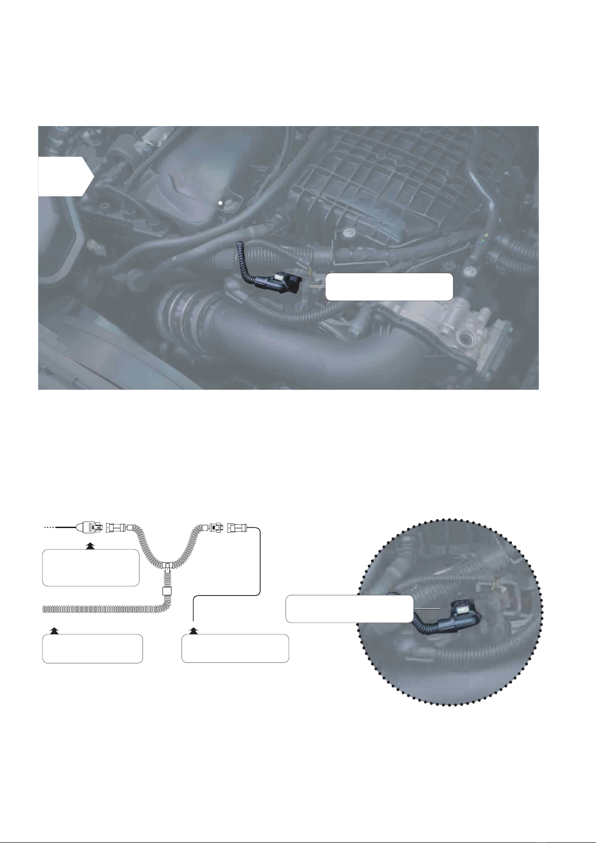
Step 4 of 6 - Connect to Supply Pressure
Pressure connection
power supply
Schematic representation:
Cable coming from
ProRacing
Cable with connector
standard o
Pressure connection
power supply
7
First locate the sensors where to connect the wiring, supply pressure sensor and
turbo pressure sensor. Usually the feed sensor is placed on the suction ange,
after the turbo, the second turbo pressure sensor is usually after the throttle on the
intake manifold.
1Supply pressure connection

4 Assembly of turbo petrol engines
•
•
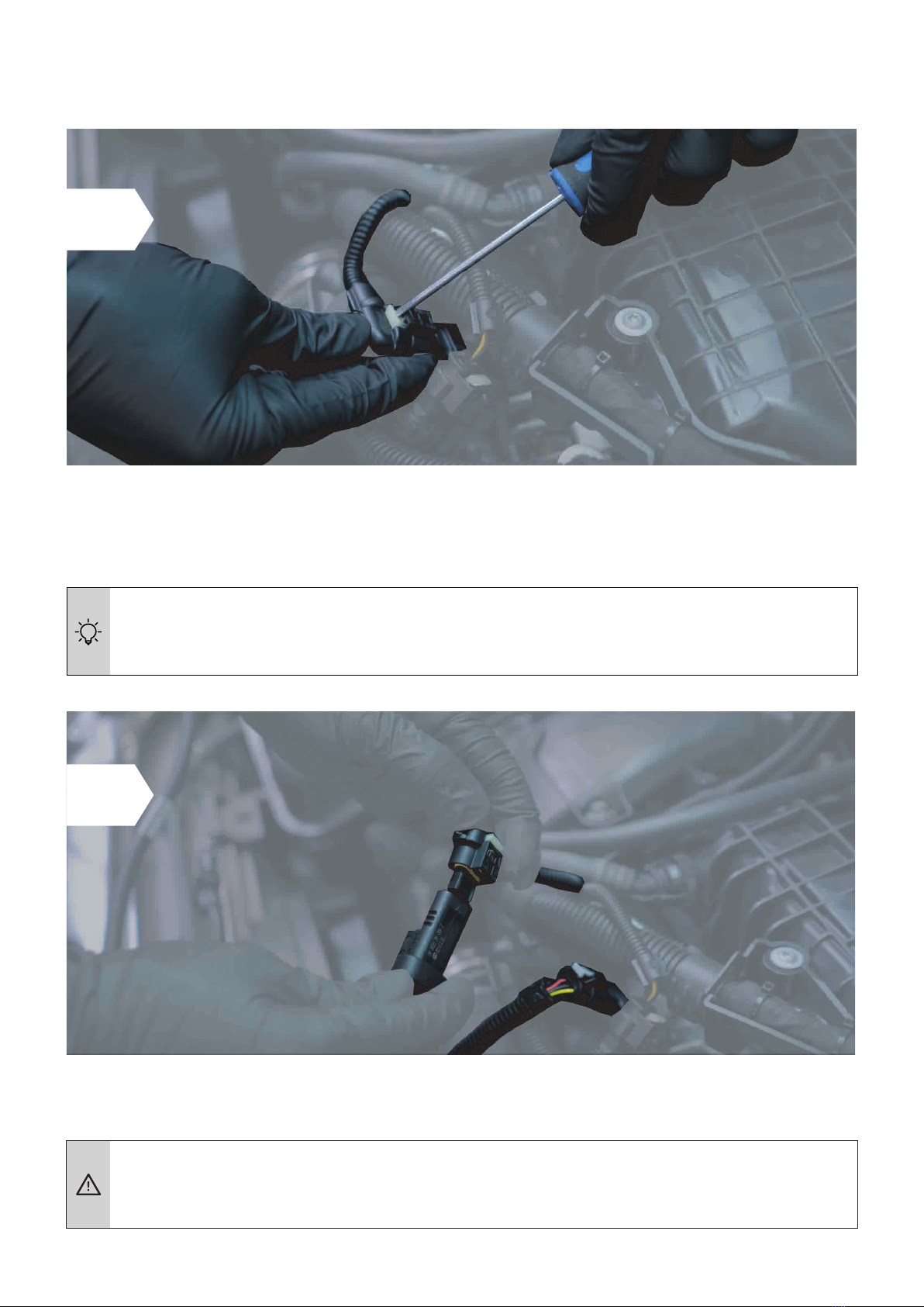
• Make sure the connector's safety clip clicks back into place:
you can hear it by CLICK.
8
To disconnect the connectors from the sensors it is necessary to press not too hard in order to raise the
release clip or move the safety catch.
We normally have 90% of the photos in the catalog of all engines, check your inbox
registration, at the time of purchase we send the specic photos in our possession.
It intercepts the suction pressure sensor located on the suction ange, releases the connectors and
connect as shown in the gure by interposing the wiring between the car sensor and the engine
wiring.
2
3
4 Assembly of turbo petrol engines
Step 4 of 6 - Connect the suction hose pressure
•
Schematic representation:
Cable coming from
Proracing
Cable with connector
series o
B
Link to
tube pressure
suction
9
Locate the turbo pressure sensor usually located after the throttle body on the
intake manifold, disconnect the connectors and interpose the wiring as shown in the gure
schematized.
1
Pressure connection
of the suction pipe
Pressure connection
of the suction pipe
10
4 Assembly
•
•
• Make sure the connector's safety clip clicks back into place:
you can hear it by CLICK.
To disconnect the connectors from the sensors it is sometimes necessary to raise the safety and then
press the release clip using not too much force and remove the connector.
It intercepts the suction pressure sensor located on the suction ange, releases the connectors and
connect as shown in the gure by interposing the wiring between the car sensor and the engine wiring.
2
3
Instructions for disconnecting the suction hose pressure connector are available on the
enclosed sheet. Disconnect the connector correctly.

5 First start-up
Phase 5 of 6 - First start test.
Phase 6 of 6 - End of installation.
•
•
•
•
•
•
•
Carry out a rst function test
•
•
Connect the control unit to the wiring.
Please note that after about 1 minute it goes into standbay mode and turns o but this is normal.
Rest Proracing with the harness securely possibly already clamped in such a way
that no moving part of the engine can create problems.
Now start the engine and check that the ECU turns on.
Turn o the engine and complete the installation of the wiring with the supplied cable ties.
If the car does not start regularly or you have reports on the dashboard
proceed with the paragraph '' Removing errors ''
Of course, our customer service is also at your disposal.
Route the corrugated pipe of the wiring along a suitable point and secure it with cable ties.
When choosing the xing point of Proracing also make sure that it is
protected from water, strong heat and vibration.
Do not put Proracing in a bag as this can form condensation
of water.
Do not x the wiring on parts that can get hot at very high temperatures,
(e.g. exhaust manifold, dpf or turbochargers.
11
If the control unit turns on during installation with the ignition o, it means that
during the connection there was still residual current in the car's wiring.
This can cause in some cases an error in the dashboard, the control unit
Engine ECU may have detected a wiring harness disconnection.
1
2
16
A
6 Adjustment without application
Factory setting.
adjustments available on the version without Application:
In case the starting setting of your Proracing is
A-0 we recommend these power steps:
Selettore S1 S2
Performance level 1 B 0
Performance level 2 C 0
Performance level 3 D 0
In case the starting setting of your Proracing is
8-4 we recommend these power steps:
Selettore S1 S2
Performance level 1 9 4
Performance level 2 A 4
Performance level 3 B 4
In case the starting setting of your Proracing is
A-4 we recommend these power steps:
Selettore S1 S2
Performance level 1 B 4
Performance level 2 C 4
Performance level 3 D 4
We ship the ECU with the appropriate setting for your vehicle.
Our setting increases the engine power leaving room for improvement, without
aect the reliability of the engine, giving smoother running and optimizing fuel consumption.
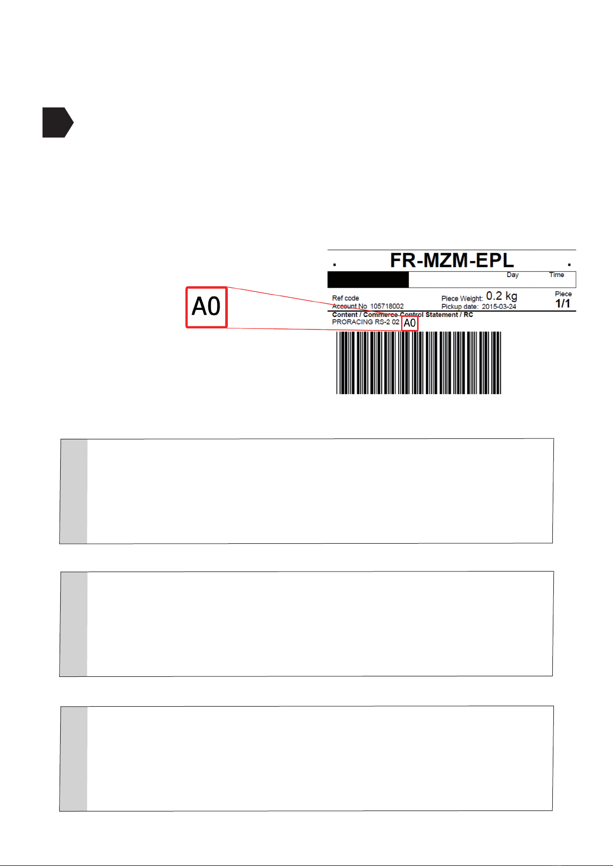
However, the default basic value is always indicated in the consignment note.
This setting is an example that identies A-0
•
•
Proracing is congured specically for your car, all parameters are adjusted for one
uid delivery and with an adequate compromise between consumption and power increases. In some
however, it is possible to further modify the settings by unscrewing the torx and opening the
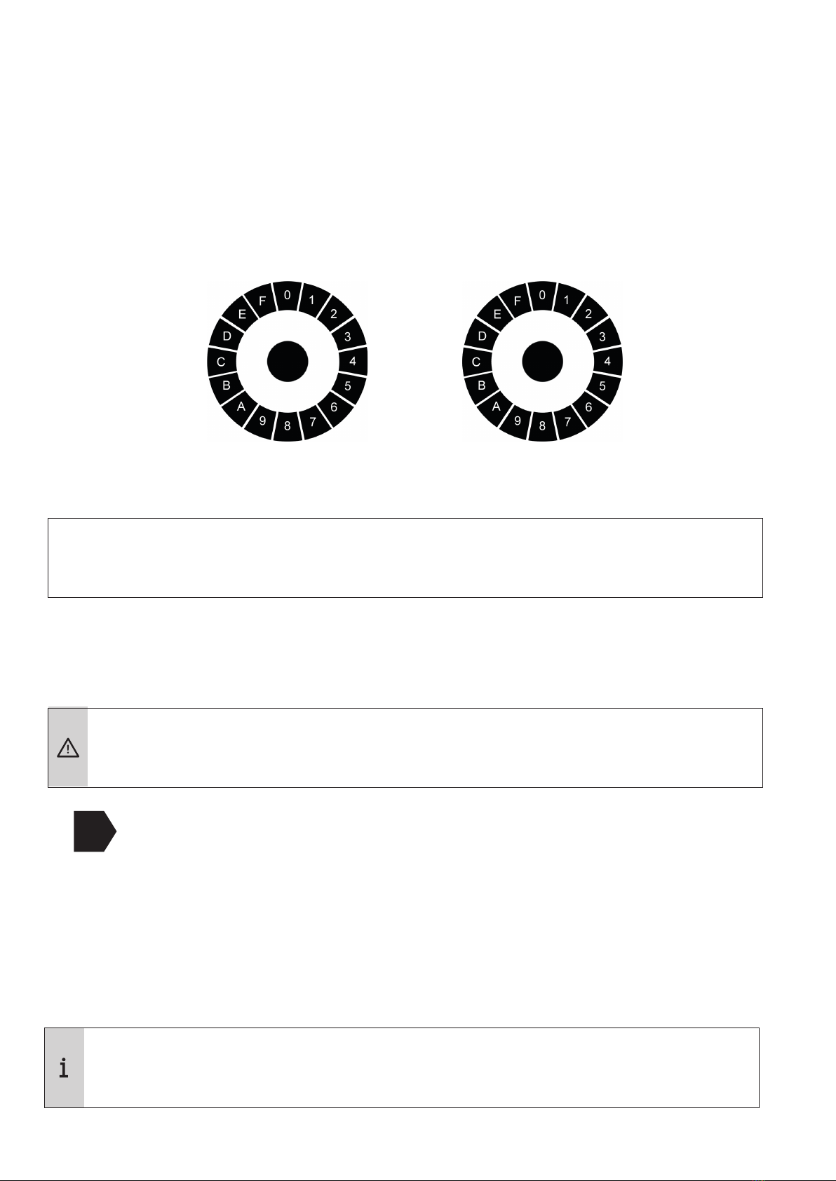
control unit. Inside there are two selectors called S1 and S2, the same selectors are present
in the smartphone application on the setting page.
17
The technicians of Proracing according to your needs can help you to calibrate in a manner
optimal (we advise you to always ask).
6 Custom adjustment.
Selettore S1: Selettore S2:
If you incorrectly change the selector parameters you may no longer have the performance
optimal, even send it to the Recovery system.
Warning: the higher setting is not always the same as the greater increase in power.
Problems with serrations, the gear is not smooth?
If while driving you feel gaps accelerating or an irregular trend, you can
use selector S2 by raising the adjustment and bringing it to position 4.
If the serration is less noticeable but still noticeable bring it into place
5 or 6 or 7.
•
•
If you change the S1 and S2 settings and have purchased the TS2 PRO version with bluetooth le
eco sport and race mappings will be recreated via argorithm based on the settings
selected.
S1 S2
The S1 selector modies power and torque, we recommend increasing one step at a time in a
clockwise direction.
The S2 selector is responsible for the duration of the performances for a greater range of revolutions,
normally this selector should not be touched to prevent the car from going into protection.
The minimum setting is 8, the maximum setting is 7 and is distributed in this sequence:
MIN 8-9-A-B-C-D-E-F-0-1-2-3-4-5-6-7 MAX
-Does the automatic gearbox give abnormal bumps at high revs?

7 Troubleshooting
Error description How to intervene
No increase of
power or porformance
they are not enough
perceptible
•
•
•
On the chapter "custom adjustment" you can nd
info on how to best set up to further increase
the performances.
Normally it is sucient to move selector S1 by one position
clockwise.
Example: if S1 is in position 8, move it to position 9
as indicated in the “customized adjustment” chapter.
The diesel engine under load
in acceleration ago
perceive a noise
of injection stronger than
normal?
•
•
•
Jerks in acceleration. • If you have jerks at the start or acceleration probably
the automatic transmission is adapting, so we recommend
proceed with the automatic adaptation.
•
•
Serrations in
acceleration in the high mids
regimes or trend
not uid at all
adjustments (eco-sport-race).
•
•
•
•
14
If you've been experiencing dash warning lights issues or don't feel enough power boost here
nd the rst support. If you do not nd the information you are looking for, you can contact assistance
customers.
If it is a noticeable increase in injection noise
under load rst take a test drive, you might hear
in acceleration a ticking.
This is absolutely normal as you are increasing
the injection pressures the noise will be more perceptible and present.
To make this noise less emphasized, lower the
race in sport adjustment or lowering the boost.
During the adaptation phase, the accelerator accompanies the throttle.
It is possible to eliminate tears by lowering the adjustment.
If in acceleration you feel jaggedness or lack of power
you have to act on the S2 selector, moving it to one more setting
high.
Usually setting the S2 selector in position 4 causes the problem
is obviated.
If setting position 4 has not solved it, move the selector
S2 in position 5 - 6 or at most 7.
Go to the custom adjustment chapter.

7 Troubleshooting
Error description How to intervene
The control light
engine or other warning
lights in the dashboard
remain on.
•
•
•
•
•
After installation, warning lights on the dashboard came on
giving error?
This does not always result in a real problem given that
if you have disconnected any connectors in the engine when it was
present current, this may have generated an error that does not
aect on the correct functioning of the motor, but it could weaken
performance for recovery system.
There is no need to worry, just turn o the light or
the reports.
Normally the lights turn o by themselves after a cycle of 5 restarts
or after about 100 / 200km.
It is possible to connect the connectors in reverse by reversing the
polarity, this surely generates an error in the dashboard.
Normally we always send photographic material afterwards
the purchase by e-mail that shows how the insertion takes place
corrected of some types of connectors that mistakenly can
be entered incorrectly.
An adjustment that is too high or higher than that allowed by the
vehicle manufacturer may result in protection or losses
sudden power. It is sucient to lower the setting
via app or external keypad. This way they will be avoided
other reports.
Dashboard light
for the control of
engine continuously
lit after a certain
walking time.
If the warning light on the dashboard does not go out by itself it
means that that particular car model needs a reset via
OBD2 diagnosis socket.
Our technicians have a specic OBD2 reset for sale
for a do-it-yourself removal via Smartphone-APP.
Or have your auto mechanic / electrician reset the lights.
15

16
7 Troubleshooting
Error description How to intervene
The car does not start
after installation.
The problem is certainly due to the fact that:
1. It is possible to connect the connectors in reverse by reversing
the polarity, this surely generates an error in the dashboard.
Normally after the purchase, we always send photographic material
by email showing how the insertion takes place
corrected of some types of connectors that mistakenly can
be entered incorrectly. Check the photos submitted
by mail, correct or incorrect.
2. You have intercepted the wrong sensors. The connectors are
identical but if the wiring is connected not respecting the correct
sensors the car will not start.
3. The bosch / siemens fuel system does not match
when adjusting Proracing, go to the Bosch / Siemens chapter
No savings of
fuel
•
•
•
If you are testing your car's performance with mapping
Proracing and testing you are using your full power
engine, consumption will be altered by sporty driving.
To make a comparison of consumption reduction it is necessary
to report driving focused only on fuel economy, before and after
the installation of Proracing.
To optimize the consumption of your car you can modify
your driving style as indicated in the chapter of our website
www.pro-racing.it in the ECO-FUEL section.

8 Contact details
Legal information
PRORACING by Privi Auto
Via Federico Confalonieri 50
20099 Sesto San Giovanni
-MI-
VAT number : 06494530964
mail: [email protected]
web: www.pro-racing.it
Our customer service is available in the dedicated section on our website www.pro.racing.it
Other ProRacing Automobile Accessories manuals


