proril TANK Series User manual
2
Download the manual in your preferred language – scan the QR-code

3
Introduction______________________________________________________________________
4
Safety Information ________________________________________________________________
4
Hazard Notice Symbols
Safety Requirements
Environmental Safety
Product Warranty
Transportation and Storage ________________________________________________________
6
Lifting
Storage
Product Specification______________________________________________________________
6
Model Number Nomentclature
Pump Design
Pump Application Conditions
Product Nameplate
Installation_______________________________________________________________________
7
Pump Installation
Float Switch Loction Installation Requirement
Electrical Connection______________________________________________________________
8
Connection Requirements (External Protection Devices)
Grounding (Earthing)
Connecting the Power Cables
Operation________________________________________________________________________
10
Prior to operation
Trial Operation Non-Float Switch
Trial Operation Float Switch
Operation
Maintenance and Inspection________________________________________________________
12
Maintenance Requirements
Maintenance General Requirements
Troubleshooting__________________________________________________________________
13
Parts Lists_______________________________________________________________________
14
Product Specification Table and Nameplate ___________________________________________
17
Table of Content
4
Dear Customer,
Thank you for choosing a PRORIL submersible pump. This manual provides instructions for the installation,
operation, and maintenance of the pump. Improper use of the product can cause personal injury and damage to
property, and may void the warranty. Upon receiving the pump, it should be inspected for damage or shortages.
Please read this manual carefully before installing and using the product, and keep this manual at hand for future
reference.
Please visit our website www.prorilpumpseurope.com for further technical reference. Thank you!
Please read this manual thoroughly before operating the product, and retain it for future reference. Disregard of
this warning could result in personal accidents and health problems, damage to the product and or product
malfunction.
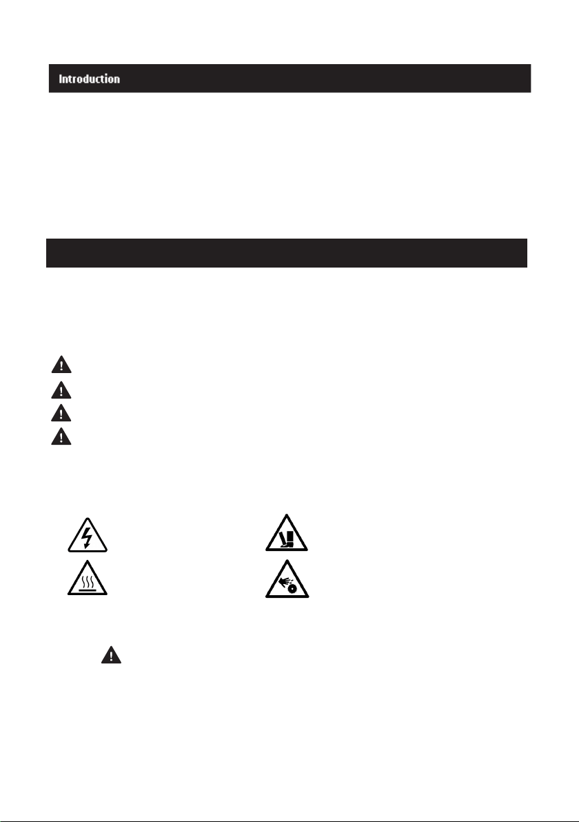
Hazard Notice Symbols
DANGER A hazardous situation which, if not avoided, will result in death or serious injury.
WARNING A hazardous situation which, if not avoided, could result in death or serious injury.
CAUTION A hazardous situation which, if not avoided, will result in minor or moderate injury.
NOTICE A potential situation which, if not avoided, could result in undesirable condition.
Complementary Hazard Notice Symbols
ELECTRICAL HAZARD CRUSH HAZARD
HOT SURFACE HAZARD CUTTING HAZARD
Safety Requirements
DANGER
Risk of electric shock - This pump is supplied with a grounding conductor or grounding-type attachment plug. To
reduce the risk of electric shock, be certain that it is connected to a residual current device or proper grounding-
type receptacle. This pump is NOT intended for use where water is occupied by people.
Safety Information

5
WARNING
•This pump has been evaluated for use with water only.
•Do not operate the product near a potentially explosive environment.
•Do not use the product in the presence of flammable liquids or gases.
•Always turn off and disconnect the pump from the main power and Lock-Out-Tag-Out (LOTO) before
carrying on inspection, maintenance, and adjustment.
•Never attempt to change the settings of all protective devices without consulting with a PRORIL
representative
•The product is designed for moving wastewater, raw and clean water. The following should not be
handled for the pump and your safety:
i ) Flammable, toxic, abrasive, crystallizing, and polymerizing liquid.
ii ) Liquid chemicals and food, alkaline and corrosive liquid.
iii ) High temperature, high viscosity, and high content solid matter liquid.
•Protect the electric plug or the end of the power cable from invasive moisture at all times. Never touch
the piping or electrical connections while the pump is running.
•Never touch the water while the pump is under operation.
•Never put the pump into operation if it has been partially dismantled.
•Hearing protection should be used in case of long exposure to noise.
•Never run the pump without water, do not operate the pump out of water or insufficient water. Do not
use the pump if the power cable is damaged. If you have any questions, please contact our
representative or company.
Environmental Safety
Do not dispose of electrical appliances as unsorted municipal waste, use separate collection facilities.
Contact your local government for information regarding the collection systems available. If electrical appliances
are disposed of in landfills or dumps, hazardous substances can leak into the groundwater and get into the food
chain, damaging your health and well-being.
Product Warranty
PRORIL’s sole obligation under this 12 months warranty shall be limited to the repair or replacement of any parts
that the Seller determines, in its discretion, to be defective. The warranty is void if the damage is caused by the
following factors:
•Improper installation
•Deficient maintenance
•Damage caused by improper use, or abuse.
•Third party modifications or attempted alterations to the pump.
•Normal wear and tear
•The pump has been used for purposes other than those for which it is intended.
PRORIL assumes no liability for the following:
•Body injuries
•Material damages
•Economic Losses
PRORIL reserves the right to change design and specifications without prior notification.

6
CRUSH HAZARD
Stay clear of the suspended load. The unit and components can be heavy. Observe accident prevention
regulations in force.
Lifting
•Make sure the pump is properly secured during transportation and cannot roll or fall over.
•Pay close attention to the pump’s center of gravity and mass. Improper lifting may result in product
damage, injury, or death.
•Always lift the pump by its lifting handle or by using suitable equipment. Use eyebolts or
lifting lugs if available.
•Never lift the pump by the motor cable or hose.
•When the pump will be carried by hand, decide the number of persons considering the mass of the
pump. When lifting the pump, ensure a good handle hold, do not bend your back, (use your knees to
protect your back), look ahead, and move smoothly.
Storage
NOTICE
•Protect the pump against humidity, heat sources, and mechanical damage.
•Do not place heavyweights on the packed product.
•Storage temperature should be within a range of -25°C to 55°C.
•For temperature up to 70°C above, storage must be within a short period and do not exceed 24 hours.
•In cold climates, do not allow water in the pump to freeze.
•After an extended storage time, the pump should be inspected before use.
•Turn the impeller by hand before using the pump.
•Check the seals and the cable entry.
Additional information on the product specific information, e.g. dimensions, specifications,
performance curves for the corresponding model will be provided separately. Please find the product
specification tables and product nameplate on page 17 or contact our representative.
Pump Design
The pump is submersible and driven by an electric motor. The pump is designed for moving wastewater, raw and
clean water. Never operate this product under any conditions other than those that have been specified.
WARNING
•This pump is neither dust-proof nor explosion-proof. Do not use it at a place where toxic, corrosive, or
explosive gas is present. Use in such a place could cause fire or explosion.
•Do not operate the product under any voltage other than described on the nameplate with the voltage
variation limit within ±10%. Failure to observe this caution may cause malfunction and breakdown of
the product, which may lead to electrical leakage or electrical shock.
•Do not use the product for hot or warm liquid over 40°C, as doing so will damage the product, which
may lead to electrical leakage or electrical shock.
•Do not operate the pump in an area that is exposed to a water pressure that exceeds any conditions
other than those that have been specified.
Transportation and Storage
Product Specification

7
Pump Application Conditions
Conditions
Description
Liquid Temperature
5°C to 40°C (41°F to 104°F)
ph liquid
5-8
Rated Output Variation
±10%
Voltage Variation without overheating
±10%, provided that it does not run
Frequency Variation
±1%
Maximum Allowable Pressure
0.2 MPa (2kgf/cm2) – Discharge pressure
Pump Installation
WARNING
•Before installing the pump, check if the cable and cable entry have not been damaged during
transportation.
•Be aware of the pump's center of gravity and weight. If the pump is not suspendedproperly, it
may lead to injury.
•Never use the pump cable to suspend the pump. Doing so will damage the cab andmay cause
electric shock or fire.
•DO NOT dismantle the product before/during installation without any authorizedinstructions from
PRORIL
NOTICE
The following installation requirement must be implemented:
•Use the pump dimensional drawing to ensure proper installation. If you have anyquestions, please
contact our representative or company.
•Provide a suitable protective barrier around the pump working area.
•Check for any explosion risk before pipe welding or use of any electrical hand tools.
•Remove any remaining debris from the inlet piping system before installing the pump.
CAUTION
During piping work be aware if welding sparks, paint, concrete, etc. come in contact with the pump, it may cause
the pump to malfunction, and current leakage or electric shock may occur.
Pump Design
CAUTION
The pump is partly-completed machinery without safeguard. The pump cannot in itself perform a specific
function, and will only be complete once incorporated into the system including all necessary protective
means/guard and control power circuit. Finally, the system integrator shall take all appropriate measures to
ensure that partly completed machinery can be placed on the market only if it satisfies the relevant provisions
with EN 60204-1 and EN ISO 12100. Safety distance and slot/gap shall comply with table 1, 3, 4 of EN ISO
13857.
The following installation instructions are only applicable when the installation has been designed
following the pump dimensional drawings.
1. Run the cable so that it has no sharp bends, is not pinched, and cannot be drawn into the pump inlet.
Installation
8
2. Connect the discharge pipe. The pump is equipped with a discharge connection for hose or pipe.
Piping work must not create air pocket in the middle of the piping.
NOTICE
The discharge pipe can be run vertically or horizontally, but must be without sharp bends. Excessive bending
could obstruct the flow of water, reduce the pumping volume, or clog the pump.
3. Install a non-return valve if the pump pit is deep, or if the vertical/lateral piping is too long.
4. Lower the pump into the sump pit. Attach a rope, chain, or wire to the handle of the eyebolts for lowering
and lifting the pump.
CAUTION
Make sure that the rope doesn't get tangled or twisted during installation.
5. Place the pump on a horizontal and rigid base, in an area that is free from and does not cause the pump to
take air in. This area must have a sufficient water level and collects water easily. Alternatively, the pump can
be suspended with a lifting chain just above the sump pit bottom. Make sure that the pump cannot rotate at
the startup or during operation.
NOTICE
For the water level required for operating the pump, refer to the pump's dimensional drawing that can be
obtained from our representative or company.
6. Make sure that the impeller rotation is correct.
7. Should there be any problems occurred during installation, please get in touch with a PRORIL
representative.
Float Switch Location Installation Requirement
CAUTION
Place the pump with integrated float switch hardware in an area where the float can properly and easily move
up and down without getting caught with the pit walls, cable, or lifting chains.
ELECTRICAL HAZZARD
•A certified electrician must supervise all electrical work. Comply with all local codes and regulations.
•Before starting work on the unit, make sure that the unit and the control panel are isolated from the
power supply and cannot be energized. This applies to the control circuit as well.
•Leakage into the electrical parts can cause damaged equipment or a blown fuse. Keep the end of
the motor cable above the liquid level.
•Make sure that all unused conductors are insulated.
•There is a risk of electrical shock or explosion if the electrical connections are not correctly carried
out or if there is fault or damage to the product.
Electrical Connections
9
Connection Requirements (External Protection Devices)
•The supply authority must be notified before installing the pump if it will be connected to the public
mains. When the pump is connected to the public power supply, it may cause flickering of
incandescent lamps when started.
•The mains voltage and frequency must agree with the specifications on the data plate. The supply
voltage and frequency variation must be within ±1% of the rated voltage. If the pump can be
connected to different voltages, then the connected voltage is specified by a yellow sticker close to
the cable entry.
•The pump is to be supplied through a residual current device (RCD) having a rated residual current
not exceeding 30mA.
•The fuses and circuit breakers must have the proper rating, and the pump overload (motor
protection breaker) must be connected and set to the rated current according to the data plate and if
applicable the cable chart.
•The starting current in direct-on-line start can be up to six times higher than the rated current. When
start-delta is used, the current is reduced by the factor 0.58 (1/3), which must be taken into account
when setting the circuit breakers.
•The fuse rating and the cables must be in accordance with the local rules and regulations.
•If an intermittent operation is prescribed, then the pump must be provided with monitoring equipment
supporting such operation.
NOTICE
It is possible to control the water level by combining float switches with an analog pressure sensor. Two
additional safety float switches can be installed in the dedicated Control System for high-level and dry-running
alarm.
•The thermal contacts/thermistors must be in use.
•The cables must be in good condition, not have any sharp bends, and not be pinched.
•The voltage drop in long cables must be taken into account. The drive unit's rated voltage measured
at the cable connection point in the pump.
Grounding (Earthing)
ELECTRICAL HAZARD
•You must earth (ground) all electrical equipment. This applies to the pump equipment, the driver,
and any monitoring equipment. Test the earth (ground) lead to verify that it is connected correctly.
•If the motor cable is jerked loose by mistake, the earth (ground) conductor should be the last
conductor to come loose from its terminal. Make sure that the earth (ground) conductor is longer
than the phase conductors. This applies to both ends of the motor cable.
•Risk of electrical shock or burn. You must connect additional earth- (ground-) fault protection device
to the earthed (grounded) connectors if persons are likely to come into physical contact with the
pump or pumped liquids.
•Connecting the Power Cables
CAUTION
Leakage into the electrical parts can cause damaged equipment or a blown fuse. Keep the end of the motor
cable above the liquid level.
1. Check the nameplate for output and voltage required for the pump.
2. Connect the power cables, including ground (earth), to the terminal or starter unit.
3. It is important that the pump should be properly grounded and provided with a leakage breaker to prevent
the users from serious electric shock injury.
4. Firmly tighten the cable entry into its bottom-most position.

10
GRN/YEL
BROWN
BLUE
Connecting the Power Cables
CAUTION
Beware that the power plug varies by country or region.
Single Phase/Three Phase Direct on Line
Three Phase Start - Delta Start
Electrical Circuit Diagrams
Additional information on the product circuit diagram for the corresponding model will be provided separately.
Please contact our representative or company.
Prior to Operation
•Never operate the pump without safety devices installed.
•Never operate the pump with the discharge valve closed.
•Make sure that all safety guards are in place and secure.
•Make sure you have a clear path of retreat.
•Never work alone.
•Beware of the risk of a sudden start if the product is used with a float switch level control and/or
internal contactor.
•Never start the pump while it is suspended, as the pump may jerk and cause serious accidents.
U1
V1
W1
U2
V2
Brown
Blue
Black
Brown
Blue
W2
T1
T2
Earth
Black
White
White
Green/Yellow
Operation
L1 L2
L1 L2 L3 Earth

11
ELECTRICAL HAZARD
Risk of electrical shock. Make sure no one gets closer than 20 m or 65 ft. to the unit when being in contact with
the pumped or mixed liquid.
NOTICE
The noise level of the product is lower than 70 dB However, the noise level of 70 dB may be exceeded in some
installations and at certain operating points on the performance curve. Make sure that you understand the noise
level requirements in the environment where the pump is installed. Failure to do so may result in hearing loss or
violation of local laws.
1. Check and verify the nameplate for output and voltage required for the pump.
2. Check the wiring, power supply voltage, the capacity of the ground leakage circuit breaker, etc.
3. Start the pump.
Trial Operation Non-Float Switch
Run the pump for a short time (1 to 2 seconds) and verify the direction if the rotation of
the impeller. If the starting jerk is counterclockwise (seen from above), the direction of its
rotation is correct. If the direction of rotation is incorrect, two of the wires should be
switched (consult a certified electrician).
CAUTION
•Make sure to check the pump's direction of rotation while the pump is not
submerged in water. Otherwise, the pump will get damage, which may lead
to current leakage and electrical shock.
•Never hold the handle while checking the direction of rotation. The starting
jerk may be very violent.
•Operate the pump from 3 to 10 minutes and perform the following checks:
•Using an AC ammeter (clamp), measure the operating current at the phases U, V, and W that are
connected to the terminal board.
•Using an AC voltmeter (tester), measure the voltage at the terminal board.
Conditions
Description
Rated Output Variation
±10%
Voltage Variation without overheating
±10%, provided that it does not run
Frequency Variation
±1%
•Proceed with the normal operation if no abnormal conditions are found during the trial operation.

12
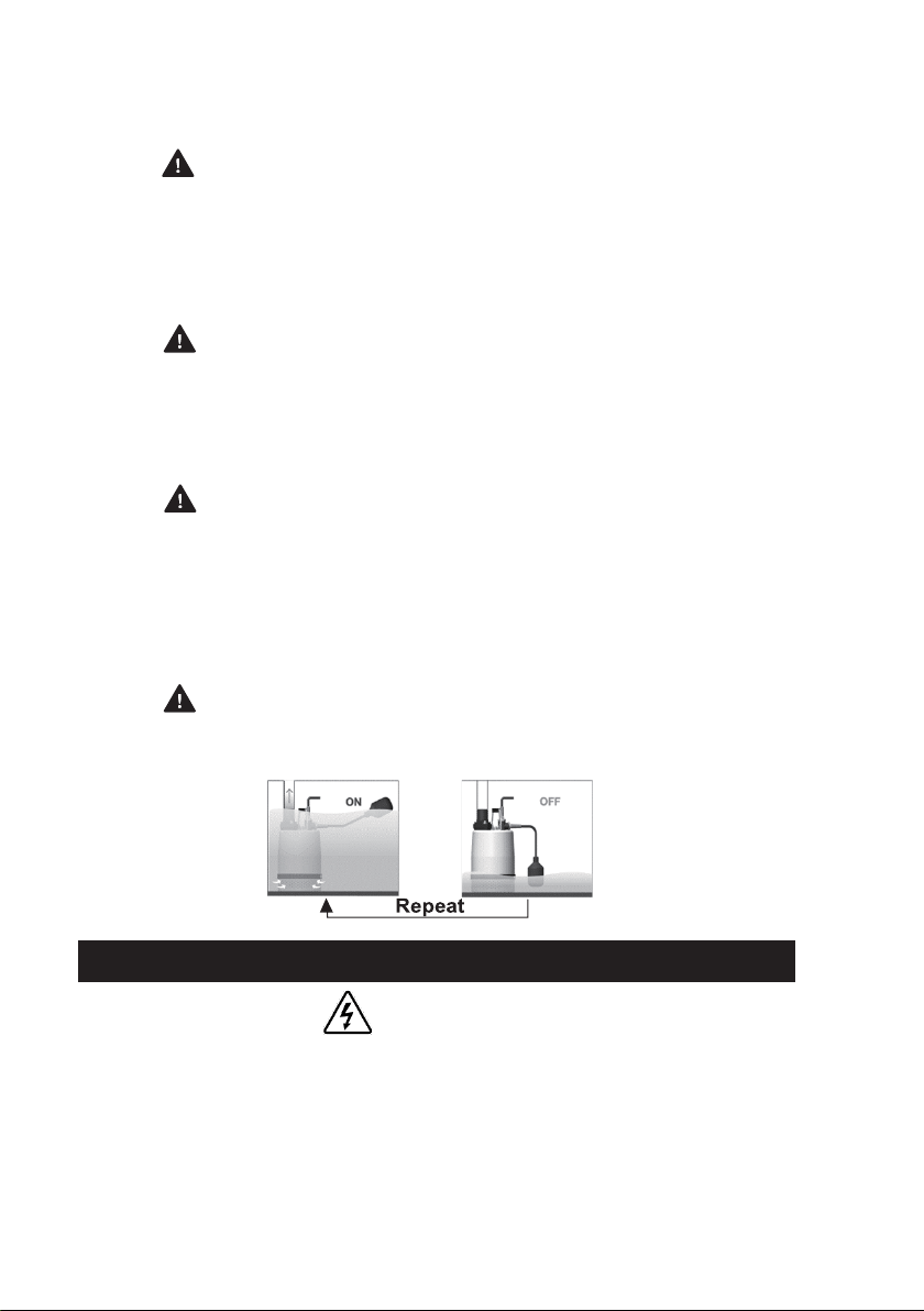
Trial Operation Float Switch
1. Direct the float switch downward.
2. Raise the float to its highest location. This will cause the pump to start.
3. Next, return the float switch to its original position. This will cause the pump to stop
4. Perform steps (2) and (3) consecutively two or more times to verify the operation.
Operation
HOT SURFACE HAZARD
Do not touch the product with bare hands during or immediately after the operation, as the product may become
very hot during operation. Failure to observe this caution may lead to being burned.
CAUTION
•Do not run the pump dry or operate it with its gate valve closed, as doing so will damage the
product, which may lead to electrical leakage or electrical shock.
•Pollution of the liquid could occur due to leakage of lubricants. Never use the product for potable
water.
1. Pay attention to the water level during operation.
2. Do not operate the pump at the lowest water level longer than 30 minutes. For details on the lowest water
level, refer to the dimensioning drawing, which is provided separately.
3. If the built-in motor safety is activated, the pump will shut down and restart automatically.
Regular checkups and preventive maintenance will ensure a more reliable and safe operation. An initial
inspection of the pump within 3 to 4 months after installation is recommended.
Subsequent inspections/maintenance can be carried out every 6 months.
WARNING
•Always disconnect and lock out the pump from the power supply before inspecting the pump.
•Make sure that the pump cannot roll or fall over to injure people and damage property.
•Rinse the pump thoroughly with clean water before working on the pump.
•The pump should not be activated if it is partially dismantled.
Maintenance Requirements
•Allow all system and pump components to cool before handling them.
•Make sure that the pump and its components have been thoroughly cleaned.
•Inspect and verify that there is no damage on the pump exterior, and that the bolts and nuts have
not loosened.
•Do not open any vent or drain valve or remove any plugs while the system is pressurized.
•Make sure the pump is isolated from the system.
Maintenance General Guidelines
•Clean all parts thoroughly, especially O-rings grooves.
•Change all O-rings, and gasket.
•During assembly or service of the pumps, it is recommended that the screws be tightened to
approximately 6- Nm (4.5 6 ft-lb). The tightening torque ensures the parts are correctly fastened and
that the pump will operate as intended
Maintenance and Inspection
13
CUTTING HAZARD
Worn impellers often have very sharp edges. Be very careful when replacing them.
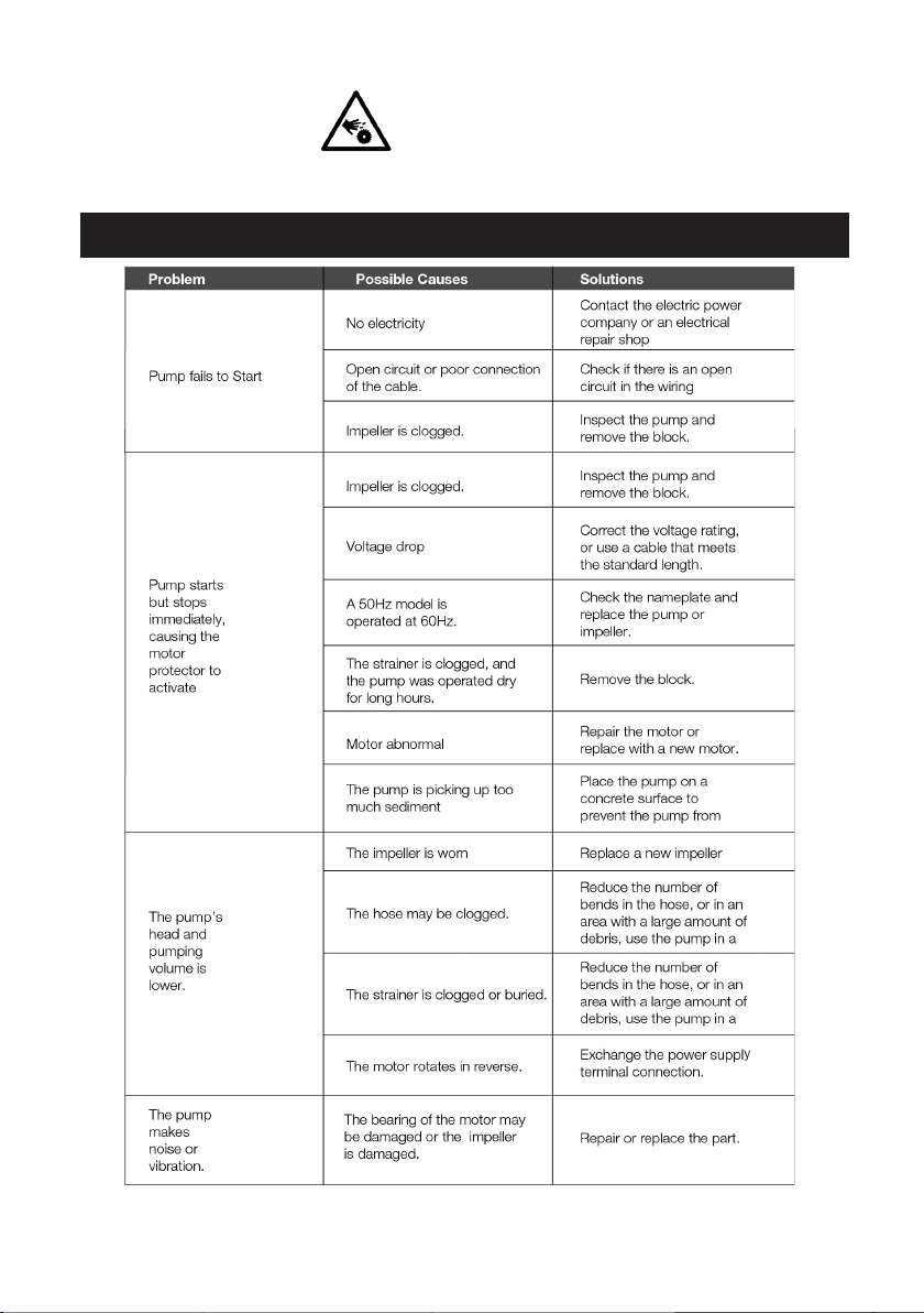
Troubleshooting
14
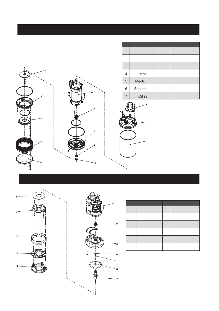
No
enomination
No
Denomination
1
Discharge
8
Shaft sleeve
2
Upper cover
9
Impeller
3
Outer case
10
Pump casing
4
Motor
11
Inlet plate
5
Mech. Seal
12
Strainer
6
Seal bracket
13
Base plate
7
Oil seal
No
enomination
No
Denomination
1
Motor
7
Agitator
2
Mech. Seal
8
Wear plate
3
Pump casing
9
Inlet plate
4
Oil seal
10
Strainer
5
Shaft sleeve
11
Strainer Base
6
Impeller
12
Base plate
Part List Tank / Tank Slim Pumps
10
11
12
13
Part List Titan / Stormy / Stormy Pro Pumps

15
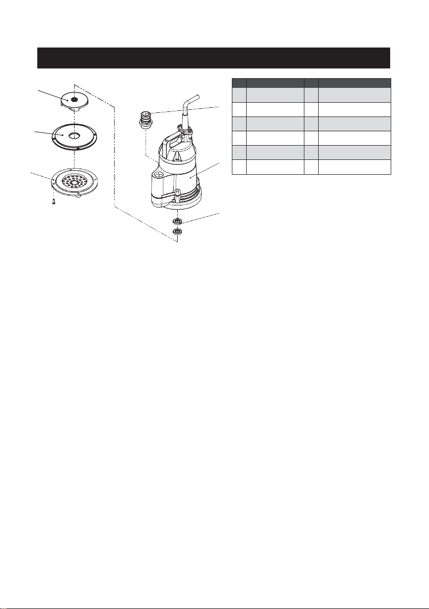
enomination
No
Denomination
1
Motor
7
Pump casing
2
Mech. Seal
8
Flange
3
Pump casing
9
Discharge elbow
4
Oil seal
5
Shaft sleeve
6
Impeller
enomination
No
Denomination
1
Motor
7
Pump casing
2
Mech. Seal
8
Flange
3
Pump casing
9
Discharge elbow
4
Oil seal
5
Shaft sleeve
6
Impeller
Part List GOCUT / GOFLOW/ GOSPIN / GOVOX/-G/-U/-S / GOMAX /
X-VOX Pumps
Part List SMART / LITE / VOX / X-SMART Pumps
16
enomination
No
Denomination
1
Motor
7
Pump casing
2
Mech. Seal
8
Flange
3
Pump casing
9
Discharge elbow
4
Oil seal
5
Shaft sleeve
6
Impeller
Part List SAVVY / JUMBO / BASE Pumps
4
5

17

18
1st Letter (year)
2nd Letter (month)
Numbers
A = 2016
N = December
Continuous number
sequence from
production
Examples:
CP 1026 ( 2018 /
November / 1026th
pump )
BS 1496 ( 2017 /
August / 1496th pump)
BN 1135 ( 2017 /
December / 1135th
pump )
B = 2017
P = November
C = 2018
Q = October
D = 2019
R = September
E = 2020
S = August
F = 2021
T = July
G = 2022
U = June
H = 2023
V = May
I = 2024
W = April
J = 2025
X = March
K = 2026
Y = February
L = 2027
Z = January
Description

19
WWW.PRORIL.COM
NO. 51, GUANGHUA RD. DASHE DISTRICT KAOHSIUNG CITY 815, TAIWAN
TEL : + 886 7 351 2306
MADE IN TAIWAN REV. MN:2021-01
2021 PRORIL. The original instruction is in English. All non-English instructions are translations of the original
instruction.
This manual suits for next models
15
Table of contents
Popular Water Pump manuals by other brands

Pentair
Pentair WCFIX 260V/3 instruction manual

OSAKA VACUUM
OSAKA VACUUM TG390M/420M Series instruction manual

Viking pump
Viking pump GP-425 SERIES Technical & service manual

Parkside
Parkside PHWW 1200 A1 Translation of the original instructions

Carlisle Fluid Technologies
Carlisle Fluid Technologies Binks E2-30 Service manual

Penguin
Penguin MTD Series manual


